Need to install and wire in a 24v vent damper and a 24 Louver actuator.

Hello all. This was brought up in a different post, and I appreciate everyone's input. I figure if it was under its own discussion it would get this figured out.
I have an lgb-7 series 2. We want to install a 24v vent damper and a 24v Motorized louver actuator for combustion air (to keep the elements out and other reasons) If the actuator does not have end switch's built in I would add a whisker or something of the sort.
The limit circuit is 120v and when satisfied it powers the 24v transformer for the burner circuit.
I know the end switch's on the damper and actuator need to be in series with the burner circuit to prove they are open.
How would I wire in both of these into this set up without killing power to the dampers when the 120v limits open. I'm assuming with a second transformer and a SPDT Relay? If so where on the diagram would these tie in? I've spent a bunch of time trying to figure it out but not sure how to do it properly.
Here are the diagrams. I appreciate everyone in advance.
Comments
-
The vent damper is on the exhaust vent? If it is, it must become part of the limit circuit, and prove open before power is applied to the rest of the boiler limit circuit. It's not a question of killing power to the damper when the existing 120 volt limits open — it's a matter of killing power to everything except the camper unless the damper is open.
Br. Jamie, osb
Building superintendent/caretaker, 7200 sq. ft. historic house museum with dependencies in New England1 -
@Jamie Hall Yes the vent damper is for the exhaust, and yes I agree power needs to be killed to everything except the damper so it can close. Thats why I was thinking a second transformer wired in right after the service switch- constant power going to the 1 terminal.
0 -
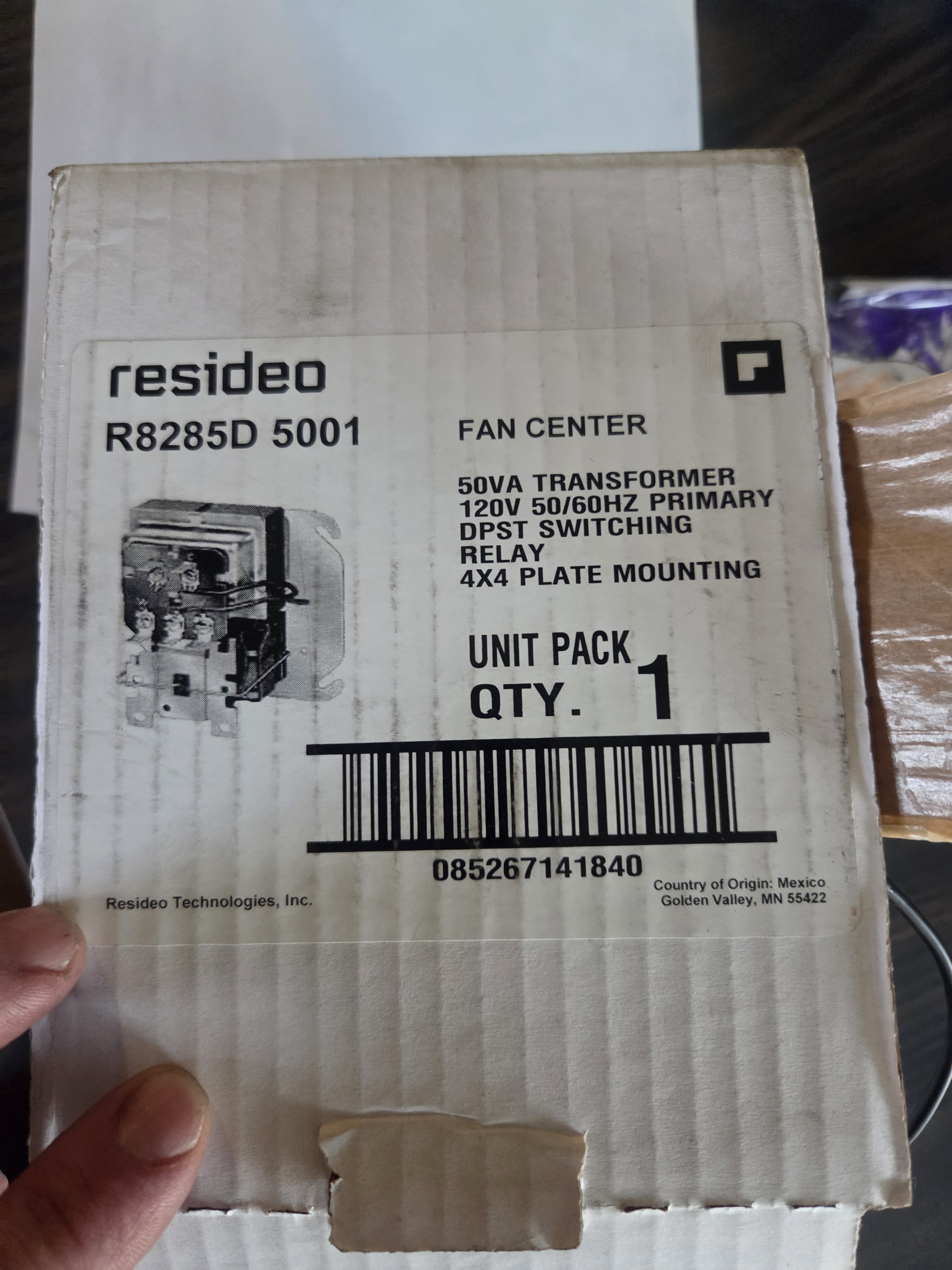
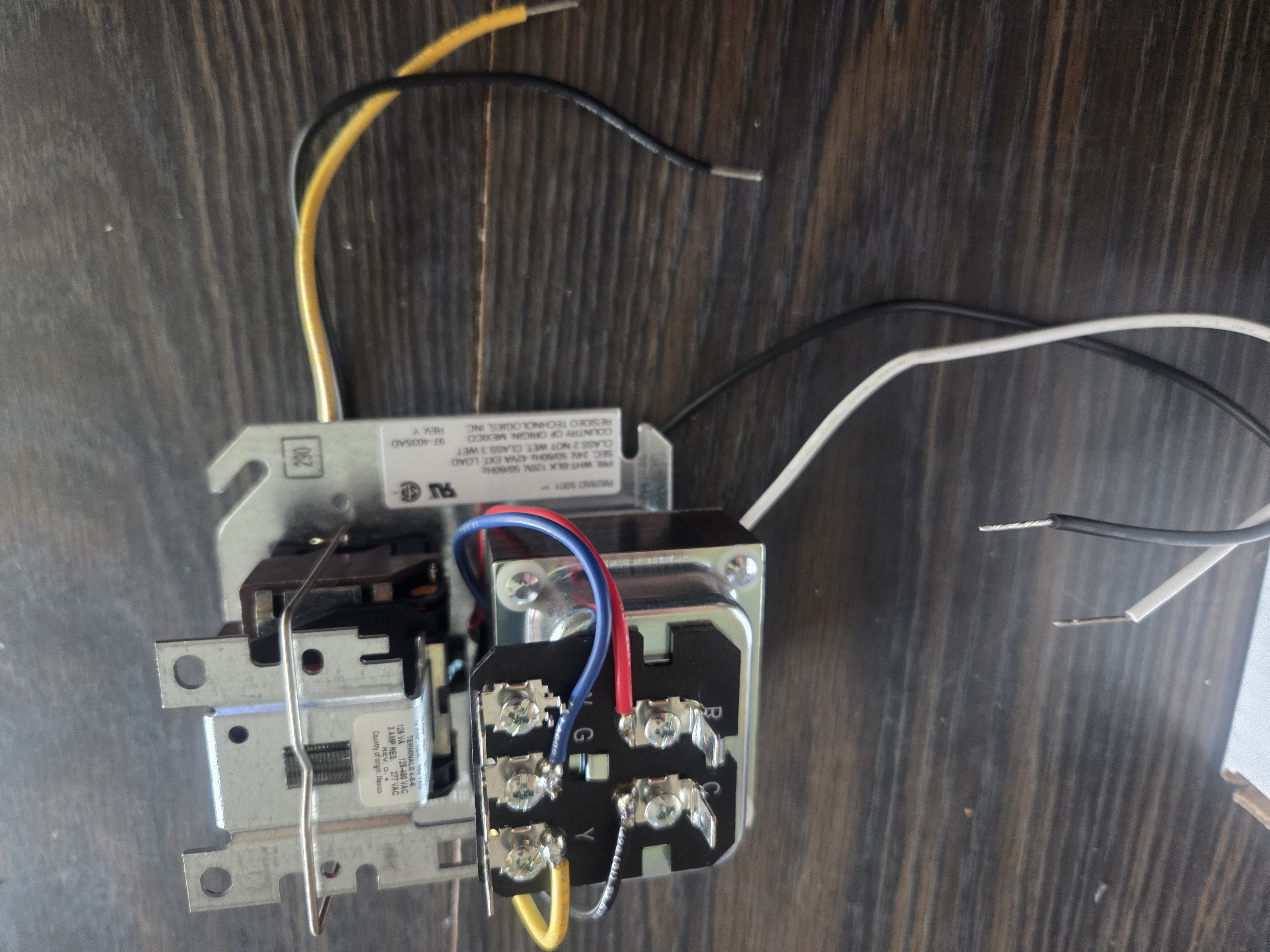
First things first. Wire the fresh air louver into the thermostat circuit. Get an R8285A fan center, like this:
Mount it on its own 1900 (4" square) box. Feed it with 120V and route the two normally open relay contact wires (black and red) out of the box through a bushing to keep them from abrading.
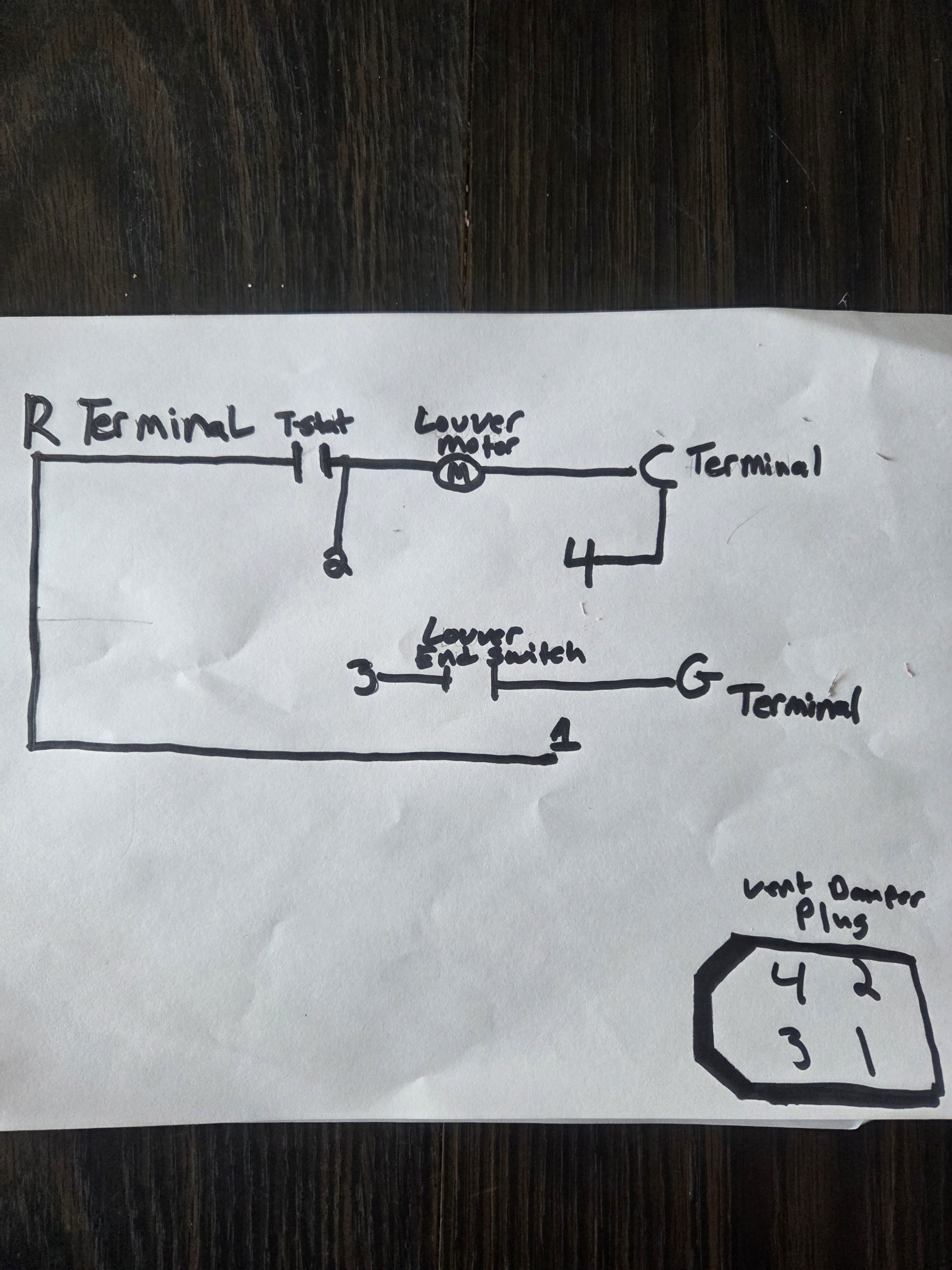
Wire the louver so it gets 24V from the thermostat when it closes. The thermostat connects between R on the R8285A and the damper motor feed. If the thermostat needs a common wire, that goes on terminal C, as does the other side of the louver motor.
Feed the end switch with the same 24V that goes to the louver motor. Wire the other end switch terminal back to G on the R8285A. This will pull in the relay when the end switch closes.
And the two relay wires sticking out of the box? These go to TT on the boiler.
Sequence of operation: On a call for heat, the thermostat sends 24V to the louver motor. The motor opens the louvers. When the louvers finish opening, the end switch closes, sending 24V back to the relay to pull it in. This closes the thermostat circuit to the boiler, which then comes on, opening the flue damper as part of its cycle.
Baltimore, MD, USA
Steam, Vapor & Hot-Water Heating Specialists
Oil & Gas Burner Service
Consulting1 -
(This is a steamer )
When one of the 120v limits open, that would kill power to the fan center leaving the damper and louver wide open correct? I'm going to make a diagram
Thank you.
0 -
Depends on how you wire it. I would feed it 120V straight from the service switch. The limits and stack damper would come after that.
Baltimore, MD, USA
Steam, Vapor & Hot-Water Heating Specialists
Oil & Gas Burner Service
Consulting0 -
0
-
If I wired it in right off of the service switch, if one of the 120 limits opened the transformer would still stay powered and the burner would still be on because of the call from the thermostat.
0 -
@Steamhead unless. I rewired the 120 limits with 24 volts directly in series with the end switches?
0 -
No. Remember, that relay for the louver motor only operates another 24V "thermostat circuit" that is part of the boiler. The limits are wired in after that- this is the factory configuration. The louver relay can open and close all it wants, but nothing will happen if the limits open.
The beauty of this method is you don't have to change any wiring on the boiler itself.
Baltimore, MD, USA
Steam, Vapor & Hot-Water Heating Specialists
Oil & Gas Burner Service
Consulting1 -
This is your wiring diagram. The actual diagram that should be on the boiler, should not show the dual burner configuration that you get from the manual, but since this is what you have offered as your diagram here is what you need to do:
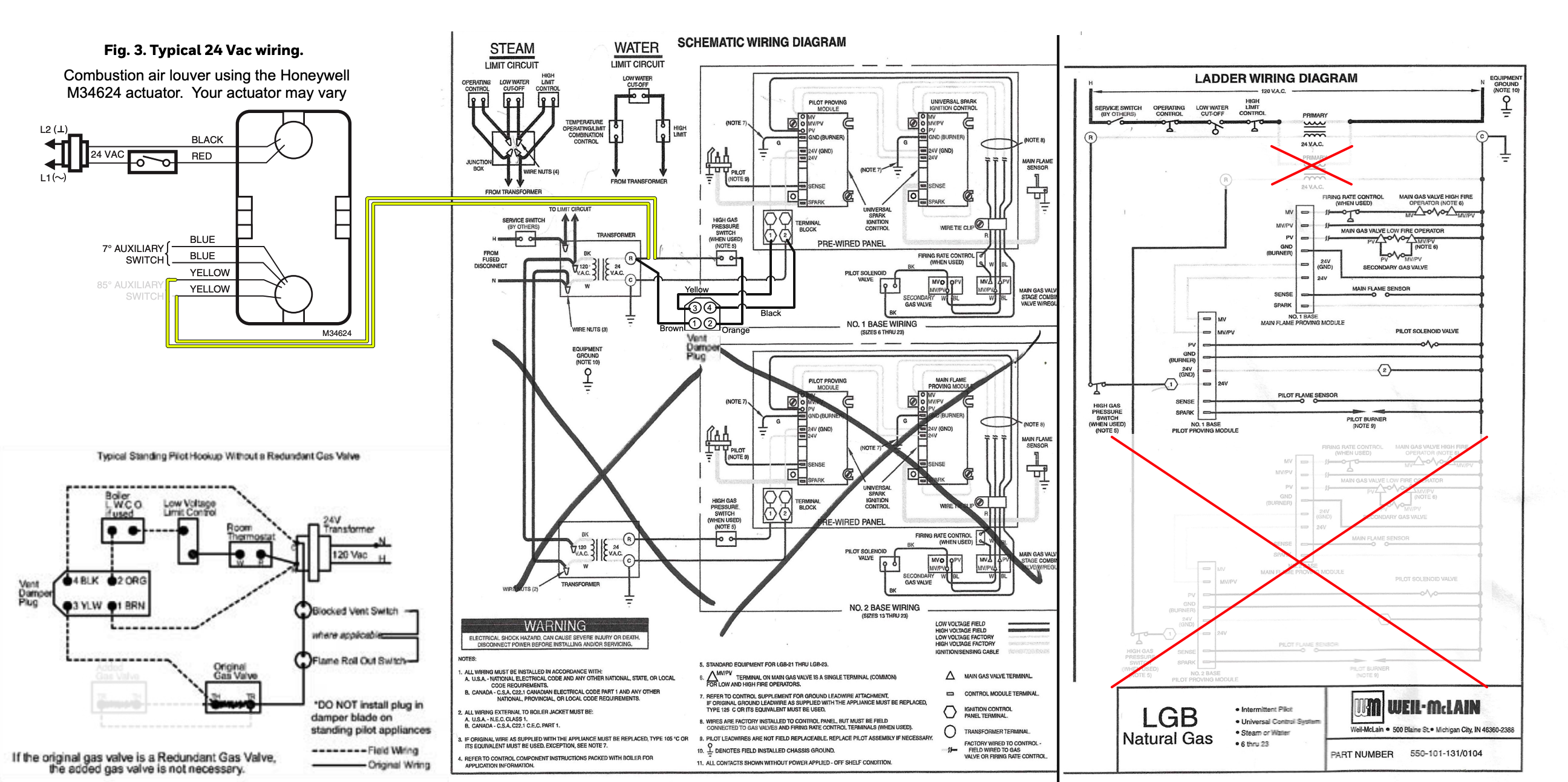
Since there is only one transformer that powers only one set of burners on the smaller LGB boilers, you can connect the Field Controls 24V vent damper to the 24V boiler transformer, as long as the boiler transformer is rated at 40 VA or greater. The Field Controls factory-recommended plug with pigtail ends FCU-8 (not the 6-pin Molex end) can be connected as recommended by Field Controls. That cable is sold separately. The Field Controls diagram is shown in the lower left of the diagram, and only the 4 pin Molex plug and wire colors are shown in the boiler schematic diagram (I did not show it on the ladder diagram).
Since commercial boilers may not have a room thermostat, you may or may not have any low-voltage control to power the combustion air (CA) louver actuator. I have elected to use a Honeywell 24-volt actuator, model M34624. You may use another brand or model to open and close your CA louvers. I recommend a separate transformer for this part of the wiring since that motor may draw too much current for the boiler's on board transformer.
When using that 24 VAC device, you need to have an operator that can switch the system on with 24 VAC and connect that to the CA louver. If another line-voltage limit opens like the LWCO or the manual reset limits, to shut down the boiler, the CA louver will lose power and spring closed, reducing the amount of air through the boiler room—even though the 24V vent damper will remain stuck open since there is no power to close it, you will still have a significant reduction on air flow thru the boiler to the vent.
This is the best option that is simple to implement and will yield some savings during standby loss when something other than the 24 v. operator shuts the burner down.
This will meet the minimum code and safety requirements if properly installed and wired. Hope this helps you get where you need to be in getting your Quote ready.
Edward Young Retired
After you make that expensive repair and you still have the same problem, What will you check next?
1 -
Thank you for the diagram/instructions Ed! That made everything click for me, I was having a hard time with it just trying to find a way to make that vent damper work all the time. But that's ok! This will work indeed and I'm very grateful that I feel confident that this will operate as intended and safe!
Yes, this defiantly helps get the quote together a ton! If I would have stopped and thought about the way this boiler was wired before I spoke with the customer it wouldn't have felt so rushed. I'm grateful for everyone's time and effort on this, truly!
 1
1


Categories
- All Categories
- 87.7K THE MAIN WALL
- 3.3K A-C, Heat Pumps & Refrigeration
- 59 Biomass
- 430 Carbon Monoxide Awareness
- 129 Chimneys & Flues
- 2.2K Domestic Hot Water
- 5.9K Gas Heating
- 122 Geothermal
- 170 Indoor-Air Quality
- 3.8K Oil Heating
- 79 Pipe Deterioration
- 1.1K Plumbing
- 6.6K Radiant Heating
- 396 Solar
- 16K Strictly Steam
- 3.5K Thermostats and Controls
- 56 Water Quality
- 51 Industry Classes
- 51 Job Opportunities
- 17 Recall Announcements