Welcome! Here are the website rules, as well as some tips for using this forum.
Click here to Find a Contractor in your area.
If our community has helped you, please consider making a contribution to support this website. Thanks!
Seeking advice, new to boilers, boiler broke over winter
Comments
-
This solution looks nice. Question, I am guessing I will have to break a 1/4" gas line off from the main gas inlet somewhere, as the main gas valve (controlled by S8610U #2) pilot also is controlled by S8610U #2, and therefore that pilot line will have no gas until it gets signal on TH-W from S8610U #2. Does the pilot gas valve controlled by S8610U #1 have a thermocouple to prove it has lit?
I ask as I did not see any mention of a thermocouple connection on the V8046C1006 pilot gas valve that was mentioned. How does the S8610U #1 know when that pilot has been proven?0 -
You have it backwards. Module 1 connects to the pilot terminal of the main gas valve that's already there. It sends 24V to the PV terminal on that valve. This sends gas to pilot #1, proves the flame, then sends 24V to module 2. The line to the V8046C that leads to pilot 2 is teed off the line to pilot 1, and the V8046C does not let gas go to pilot 2 at this point.
When module 2 gets 24V, it opens the V8043C to send gas to pilot 2. Now pilot 2 gets its gas, and when it lights and flame is proven, module 2 sends 24V to the main gas valve terminal MV, and the main burners will light.
0 -
No thermocouples.
OK the way that @Steamhead describes is not what I envisioned drawing the last drawing. It may work the way he describes. However this returns to the unknown of 'will the Gas valve's pilot circuit support two pilots'.
The way I drew it the autonomous pilot gas valve has it own gas source. Like repurposing the taps at the gas manual On-Off valve. So the autonomous pilot gas valve proves first, module #1. With an autonomous pilot gas valve that has it own gas source it really does not matter which actual pilot proves first, it just becomes a matter of the sequence and MV wiring.
As you can see there are different ways to get this done. One down side of this method is if only one pilot proves (the first) you have the equivalent of a standing pilot and no heat until it is realized some thing is wrong. Using the logical AND relay method it does not easily have that scenario, but it is more wiring.
 National - U.S. Gas Boiler 45+ Years Old
Steam 300 SQ. FT. - EDR 347
One Pipe System0 -
Each S8610U Intermittent Pilot module has its own pilot. And ignites its own pilot.
Each S8610U Intermittent Pilot module has its own igniter spark rod with the pilot assembly which verifies the flame via Flame Rectification detection in the module through the spark wire.
Each S8610U module works autonomously as far as each pilot is concerned. So in this case both pilot assemblies would need to be replaced not just the one, maybe that is where the confusion lies. With a standing pilot (which you do not want) that would use a thermocouple. S8610U Intermittent Pilot modules do not use thermocouples.
If you wanted to reuse one of the pilot assemblies you would need to have a standing pilot.
 National - U.S. Gas Boiler 45+ Years Old
Steam 300 SQ. FT. - EDR 347
One Pipe System0 -
@109A_5 said: "If you wanted to reuse one of the pilot assemblies you would need to have a standing pilot."
The Y8610U kits do come with an electrode that fits most pilot assemblies. But if I were doing this, I'd get new pilots- either the Honeywell/Resideo Q345U or Q3451U if they are target types, or the Q348U or Q3481U if they're batwing type. The 3451 and 3481 come with built-in spark leads, the other two do not and need separately provided spark leads.
0 -
Looking at the picture of the kit, you basically need two kits, module, spark wire, spark assembly, wiring harness (or you could fabricate your own second wiring harness)), you just don't need that gas valve type that comes with the kit as a second gas valve (if you go that route).

Another thing with the kit is I don't see a mounting assembly for the pilot assembly.
Also looking at the kit I don't see the actual pilot, so maybe they assume you just remove the thermocouple stuff and replace it with the spark assembly. Maybe the spark assembly slides in where the thermocouple stuff was (hopefully).
I was envisioning the kit came with a pilot assembly like this below. Apparently not.
 National - U.S. Gas Boiler 45+ Years Old
Steam 300 SQ. FT. - EDR 347
One Pipe System0 -
@109A_5 said "Another thing with the kit is I don't see a mounting assembly for the pilot assembly.
Also looking at the kit I don't see the actual pilot, so maybe they assume you just remove the thermocouple stuff and replace it with the spark assembly. Maybe the spark assembly slides in where the thermocouple stuff was (hopefully)."
You nailed it- the spark electrode assembly replaces a standard thermocouple.
0 -
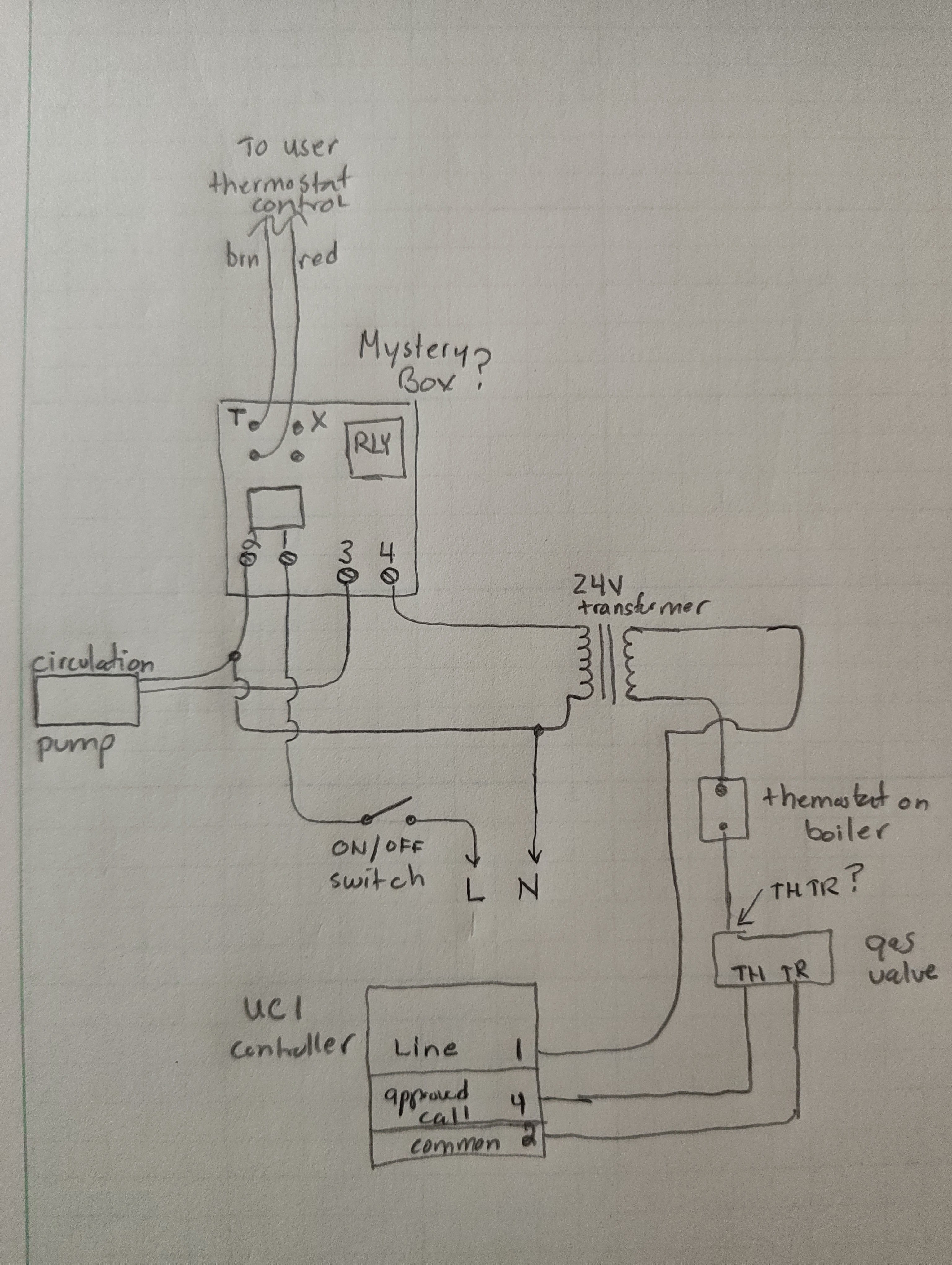
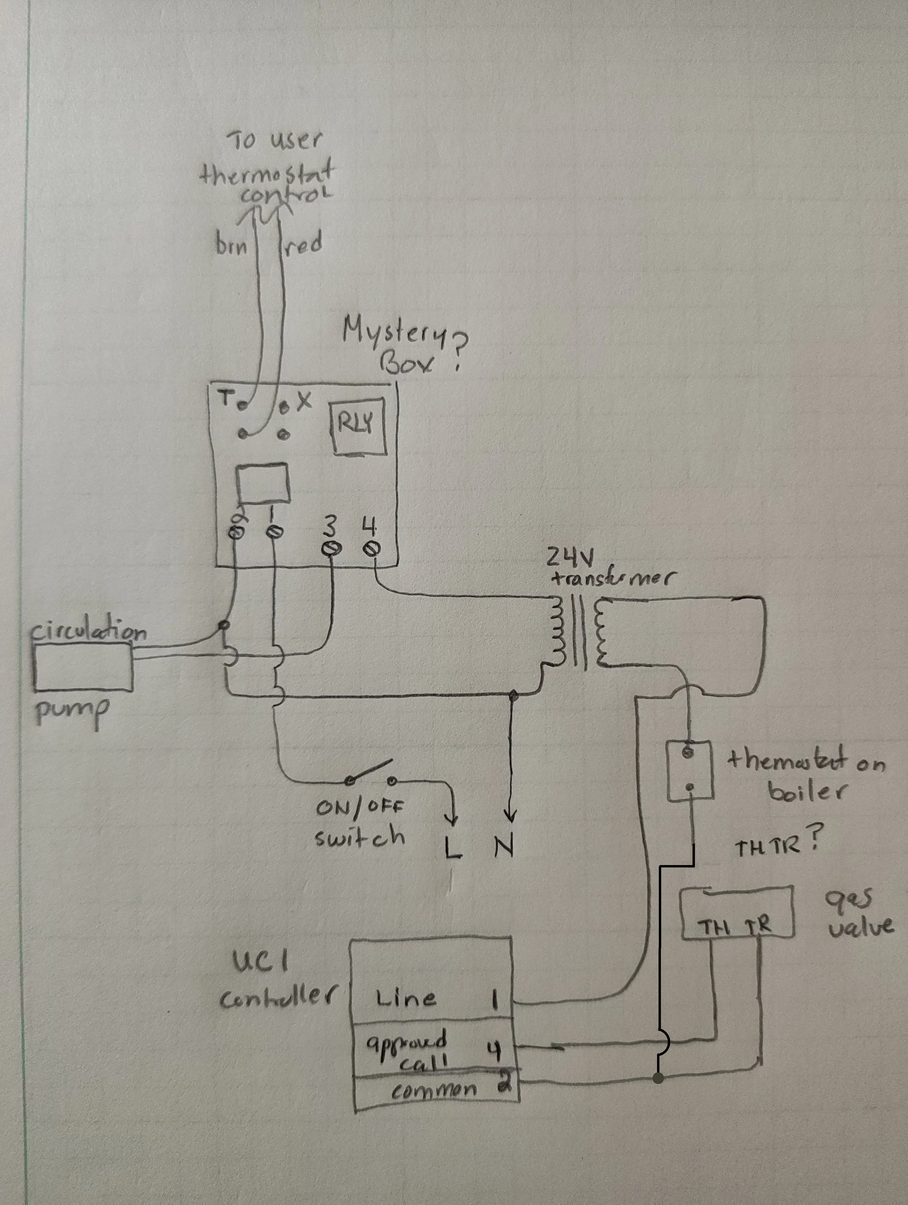
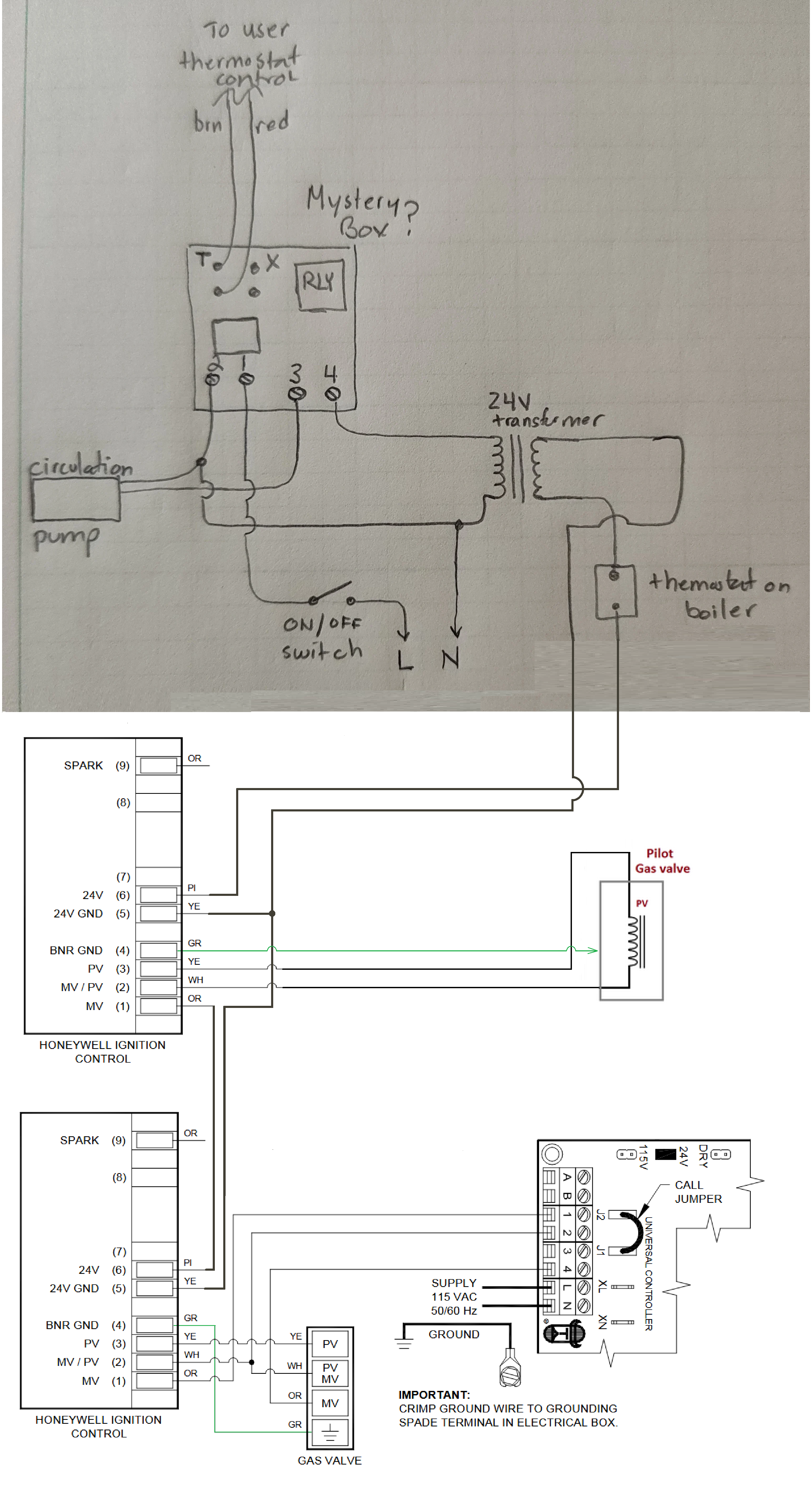
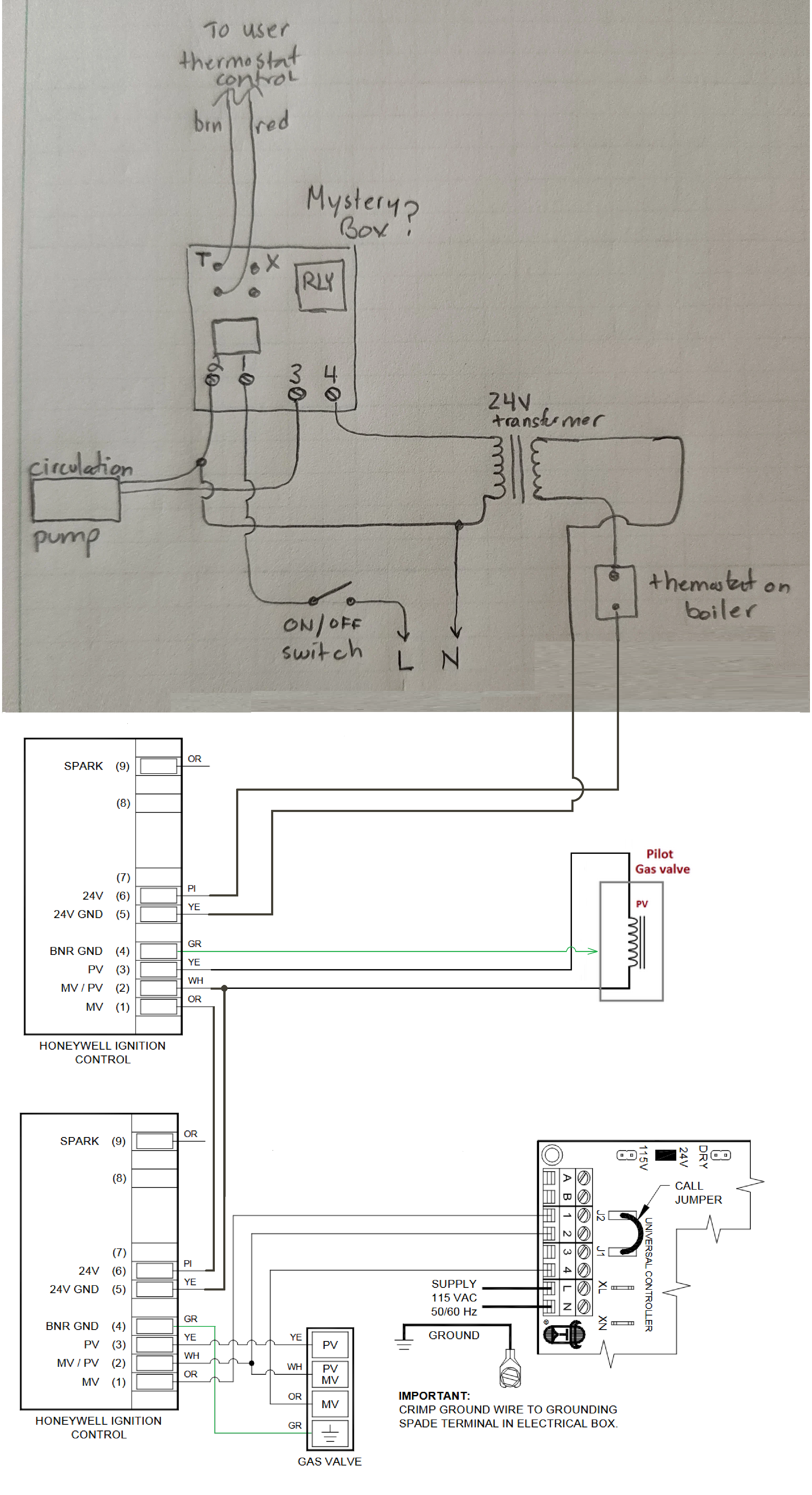
Hello, finally back on this unit, I replaced the auto fill, back flow and am now trying to install/wire the new y8610U, the problem is that there was a lot of activity in the room, some wires were knocked around, and I am not 100% sure if what was there is "correct" I am uploading a schematic of what I think was there. Is this how I should wire it back?
I have no idea what the mystery box is, but I am including a picture of it. I think I should replace the thermostat, I have no real way of checking it without firing up the boiler. do they fail often? It sure looks like it may be old.This is the diagram I have:
This is the Mystery Box:
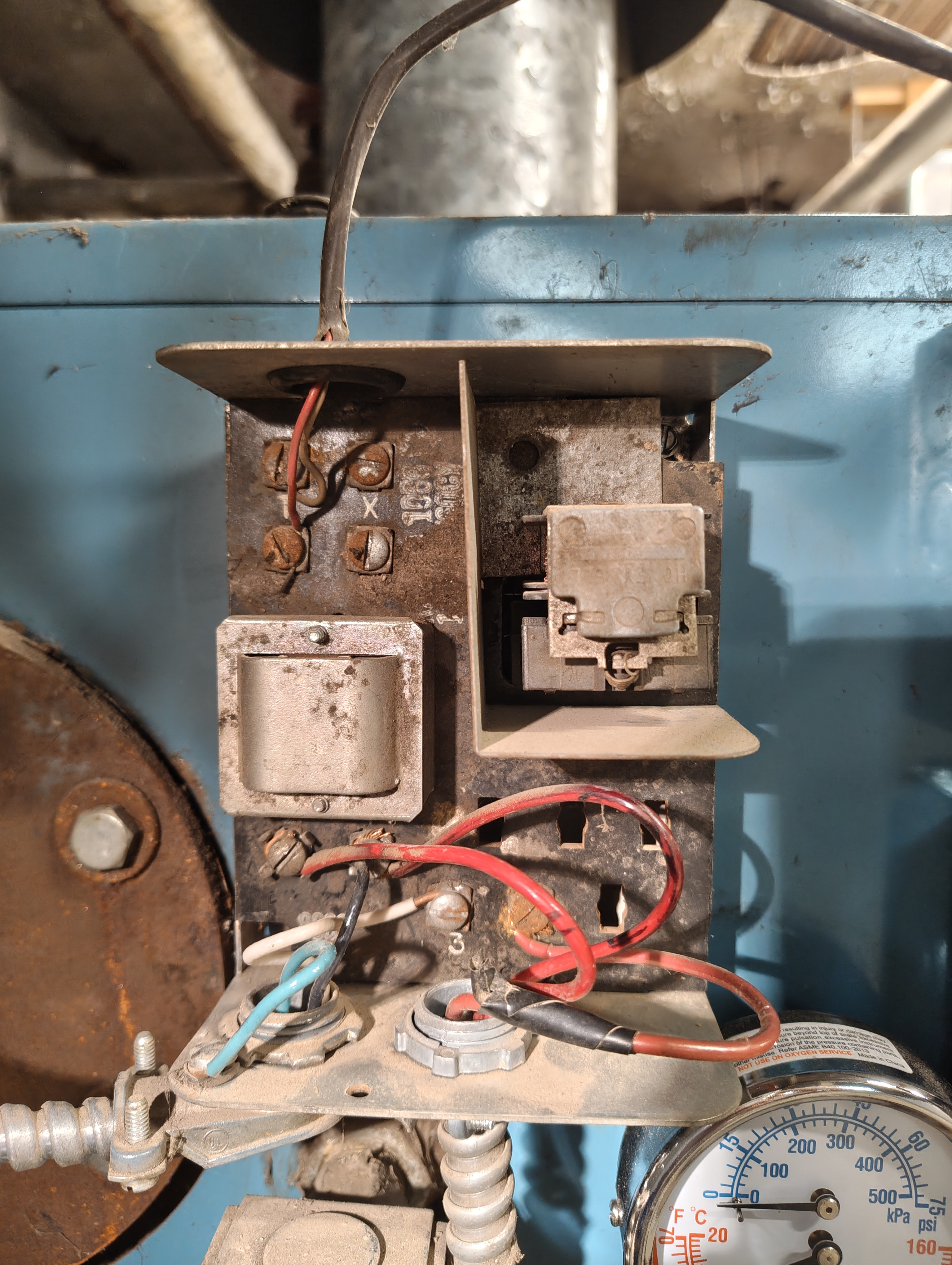
The relay on the mystery box can not possibly work, as it is broken. Should it work, or did someone just hack and slash this box to use the transformer on it to power the thermostat (the user interface). I have also never seen someone use all RED wires for line and neutral before.
Thanks.
0 -
Relay (mystery box) looks trashed. For starters you need to move the circulator "hot" wire to terminal #4 on the relay, keep the transformer hot on #4 as well. Then you need to put a jumper between terminals #3 and #1 on the relay. 120 volt hot stays on terminal #1.
What is the UC1 ignition control? and what other limit and safety controls do you have?
0 -
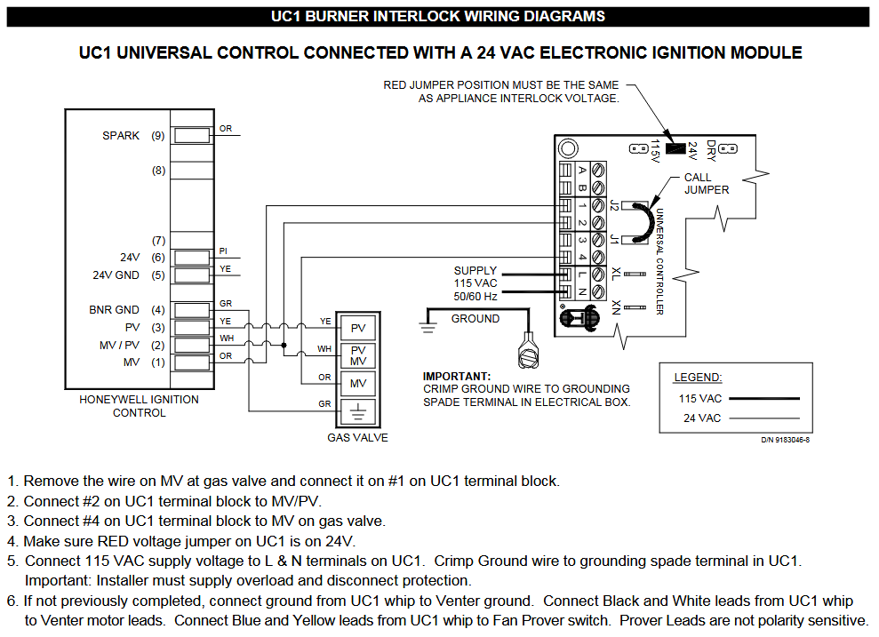
Sorry about that, the UC1 is a Tjernlund Products, Universal Control 1, it turns on the blower motor fan (it has a power fan for exhaust). https://tjernlund.com/product/uc1-universal-control/
The relay box (mystery box) is more than just a relay though, I think?? I think the small box on the left is a transformer for the user interface (thermostat)? Is this a generic thing I can purchase?
0 -
Yes the relay is a Honeywell product Supply House.com. If you are not using the X & X terminals you can get a RA89A Honeywell relay.
Tjernlund has different models
of the UC-1. Don't know if the wiring has changed between models. See the attached or look on their site
0 -
Aha. I did not have this picture, but I see clearly now.
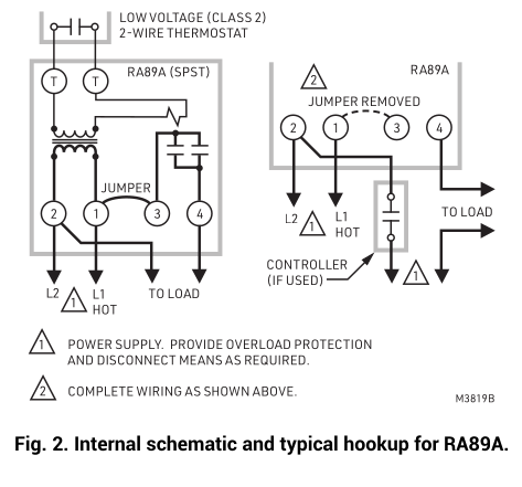
Ok, totally solved the mystery box issue.
I forgot to answer, I think the only other limit/safety control (outside of the UC1, which seems to just start the exhaust blower) is the thermostat, which seems like it is 40+ years old.
On the UC1, it says on the outside 3/4HP, Job code 02181506. This might not mean much, but this picture looks exactly like mine: https://www.supplyhouse.com/Tjernlund-UC1-TJERNLUND-UC1-Universal-Control.0 -
I am still seeking advice on the thermostat (the one with the probe in the boiler)… should I replace that thing, or just try to turn it down until it opens to see if it works (not sure if it goes that low)? Not even sure what they are really called, when I look up thermostat at supply house, well, I get like 1000s of things that do not look like that :)
0 -
-
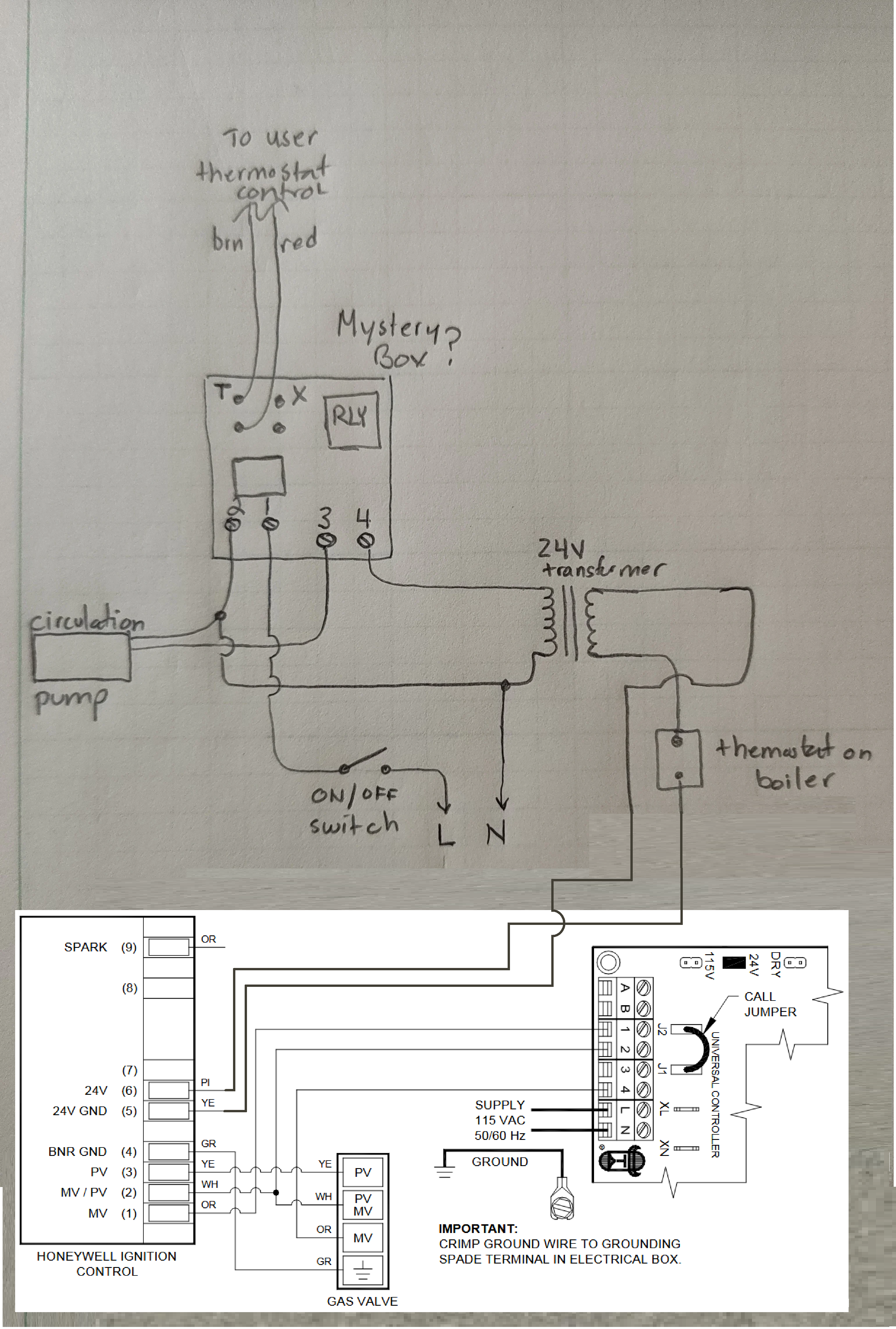
Back on this unit after a hiatus, if you look at the picture above "Mystery box" titled "This is the diagram I have", I am now installing the S8610U unit, and have it installed and I am hooking up wires. However, after I plug in M, MV/PV, PV to the gas valve, I need to connect 24V gnd, 24V and TH-W. One problem is that if you refer to my diagram, the reality is that the "C" wire on the 24v transformer seems to be connected to nothing. In fact I have an older picture I took of the unit before anything was done, and it is just hanging there in space.
Again referring to my above hand drawing, the "THTR?" arrow is pointing to a guess at where the red wire was on the original unit, but in reality, it is not connected. How would I wire this up? The UC1 box fires up the vent fan. Not sure how this is supposed to work (electrically).
I am assuming I want the picture on page 14 of the manual (below), but then were and how would UC1 get wired in? Do I even want it wired like this? Maybe I do not (I do not have limit switch "2" or a "Limit controller" at all.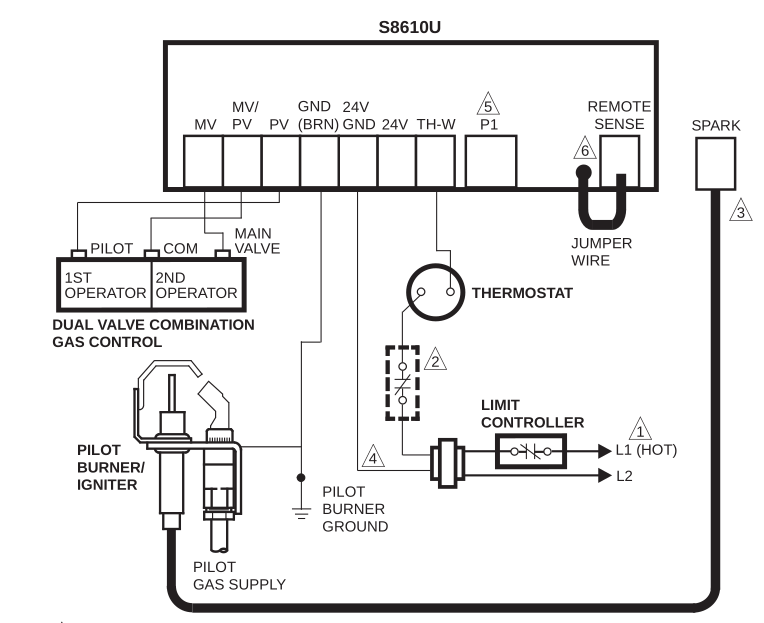 0
-
Well I am lost. I will try to make some sense of what you are doing. But I fear I will have to re-read the whole thread, too much time has elapsed. Presently it seems you are trying to replace an Aquastat with an ignition module…
Why ???
Did your system originally have a standing pilot ?
National - U.S. Gas Boiler 45+ Years Old
Steam 300 SQ. FT. - EDR 347
One Pipe System0 -
The gas valve is from the S8610U "kit", it came with a new gas valve and I am using that one.
Even if I follow the image you sent, I am still unsure of how / where the 24V power transformer comes into play, and where in that chain the aquastat goes. I am not trying to get rid of the aquastat, but it sure seems like it was disconnected (not sure how it was working).0 -
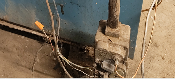
Still reviewing the thread. Do you have a better picture of the wiring as you found it ? The picture cuts off some of it. I would think the way it was and blending in the new equipment, the crusty relay unit controls the circulator and the primary of the transformer. The secondary of the transformer through the Aquastat (below the relay unit) would now supply 24 VAC to the new ignition module during a call for heat.
 National - U.S. Gas Boiler 45+ Years Old
Steam 300 SQ. FT. - EDR 347
One Pipe System0 -
Ah that is likely. I am not sure a) would that have worked and b) if so, how would I translate that over to the new system?
0 -
I actually rummaged through my photos earlier, that is the only one. The brown on the left, with the white wire (24V transformer) and the red wire (24V transformer other side) is the same wire as the other brown wire that goes off picture (it goes down and back up). On the gas valve in that picture, all of those wires go to UC1, and only three are connected at the UC1. White to common, Green to approve call and Black to "line".
0 -
Did you get the dual pilot issue sorted out ? I saw some reference to that on the previous page.
National - U.S. Gas Boiler 45+ Years Old
Steam 300 SQ. FT. - EDR 347
One Pipe System0 -
Ah, for the time being, I was going to try it with one pilot (it was working before, good or bad, so I want to get it back to "it works" before I go to "and I am modifying something even more").
0 -
No problem, just thought I add it while I was thinking about it.
National - U.S. Gas Boiler 45+ Years Old
Steam 300 SQ. FT. - EDR 347
One Pipe System0


Categories
- All Categories
- 87.8K THE MAIN WALL
- 3.3K A-C, Heat Pumps & Refrigeration
- 60 Biomass
- 430 Carbon Monoxide Awareness
- 133 Chimneys & Flues
- 2.2K Domestic Hot Water
- 6K Gas Heating
- 124 Geothermal
- 170 Indoor-Air Quality
- 3.9K Oil Heating
- 79 Pipe Deterioration
- 1.1K Plumbing
- 6.7K Radiant Heating
- 397 Solar
- 16.1K Strictly Steam
- 3.5K Thermostats and Controls
- 56 Water Quality
- 51 Industry Classes
- 51 Job Opportunities
- 18 Recall Announcements