Head Pressure & GPM calc...

I wanted to do a deep-dive and really calculate my GPM and head-pressure; something I don't think was done in 1999 when my current 126,000 BTUh SlantFin boiler was installed. —Taco 007 was installed with it. Before then it was the in-line Taco 110. I'm in a 2-story home, with some long pipe runs, and one of my zones has eighteen 90degree elbows.
One zone comes up to 6.8GPM at 22feet of Head, and the other comes up to 5.7 GPM at 18feet of head. so…… If both zones call at once, I need a pump that moves about ~12GPM at 22feet of head. Remember that this house used to have an in-line Taco 110 connected.
Taco007 won't handle this. I can provide a summary of my data & calculations if anyone wants to help determine if I'm way out in left field on this. Thanks!
Comments
-
It is a bit complicated but there is really no such thing as head pressure. Head is the energy contained in the hydronic system, measured in feet of fluid. Pressure is a measurement of force, typically psi is used in hydronic systems.
A deep dive here.
Or a snapshot here
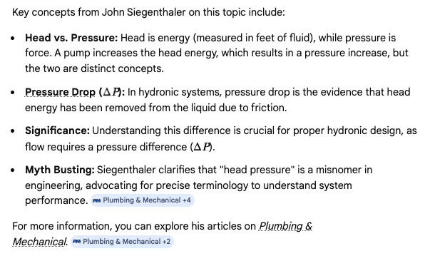
Circulators add "head" energy to a closed hydronic system. All the piping, components in the circuit use up or consume that head added. Pressure is used to determine the amount of head added to a circuit.
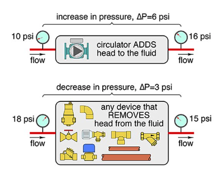
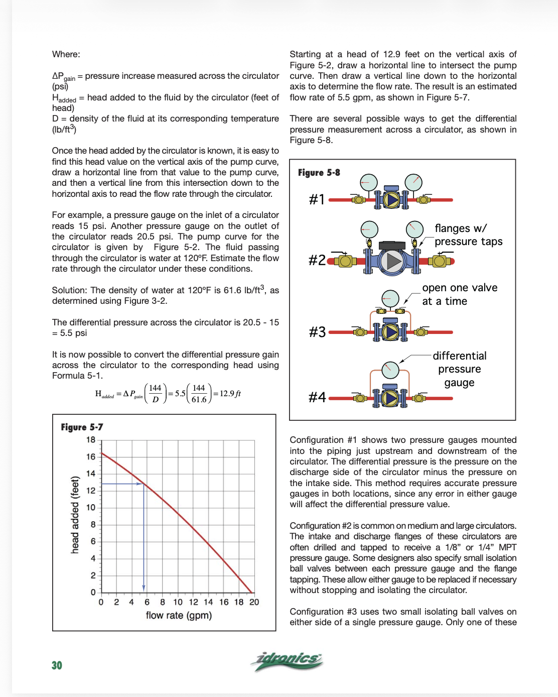
The simplest way to know or measure energy being added by the circulator is check pressure on inlet and discharge side when it is running. Fig. 5-8 has some examples of how to use a gauge to do that. I prefer a single gauge so you do not have error between the two gauges. A small circ is not adding that much pressure, so you want an accurate number from the same gauge.
Idronics 16 takes you through the steps to determine with this pressure measurement, how many GPM the system is moving using the pump curve from the brand and model of pump you have, Fig. 5-7.
If your system is a typical 3/4" fin tube circuit, generally in the 60- 80' length, 22' head would be an unusually high number.
Use the steps in Idronics 16 to see if you can get more accurate numbers
 Bob "hot rod" Rohr
trainer for Caleffi NA
Living the hydronic dream1 -
Are you sure about those 'head' numbers? They seem really high. You should show the math.
Are these zones separated by zone valves and one circulator?
If you're math is somehow correct, you would only need a 7gpm circulator @ 22' of head. But let's go over the math.0 -
if the math is correct then OP would need to add both zones flowrates together which comes out to about 12GPM. flowrate doesn't work like pressure drop where you just take the highest number. either way the head calculation feels really high, and the flowrate calculations may be a little off. almost like just trying to figure out how to move the total boiler capacity at a 20 degree delta rather than a known load and calculating flowrates based on emitter requirements to heat the space. we get way too stuck on the 20 degree delta T, more important to mind recommended velocity restrictions to avoid noisy systems imo.
 1
1 -
@e070924 said: "I can provide a summary of my data & calculations if anyone wants to help determine if I'm way out in left field on this."
I would like to see the numbers.
Often pump head and static head get intermixed when they are two separate measurements. I used to think of head as pressure until I read that book by Siegenthaler. It makes sense to me now after years of not understanding this stuff (only a few years though—I’ve been infallible ever since the 1994 publish date).
Edward Young Retired
After you make that expensive repair and you still have the same problem, What will you check next?
 2
2 -
OP here - I'll give a summary of the math soon. I did take into account the BTUh-per-foot of my fin-tubing. I proved to myself that my boiler is NOT undersized; I thought it was. I was using a Delta-T of 20degrees. -Lastly, I did watch some Taco-produced videos, so that's where I got all my formulas from. I also see that when simultanious zones call.. You add together the GPM's but NOT the head. You should use the highest calculated Head when looking across all zones. Thanks for helping with this; I'll get the numbers for you…
0 -
That sounds correct. The assumption of a 20°F ∆T is common; however, it does not always work out perfectly in real systems. Some short zones will have a smaller ∆T, while others may have a larger ∆T. The bottom line is that the average ∆T of all zones operating at the same time represents the actual system ∆T.
With that information, you can calculate the GPM based on the BTU output and the ∆T to determine the third variable, which is flow rate. To get a more accurate value, you should set the thermostat to call for heat and measure the burner run time over a period of time.
For example, if you have a 100,000 BTU output boiler and the burner operates for 10 minutes on and 5 minutes off, repeating that cycle over an hour, the burner runs for 40 minutes out of 60. That means the actual average heat output is about 66,667 BTU per hour.
Using the standard hydronic formula (BTU/h = 500 × GPM × ∆T), if your system has a 20°F ∆T at 66,667 BTU/h, the flow rate would be about 6.7 GPM. If the ∆T is closer to 15°F, the required flow would be about 8.9 GPM.
It’s all mathematics—and your algebra teacher wasn’t wrong when they said you would need this someday in the real world.
Edward Young Retired
After you make that expensive repair and you still have the same problem, What will you check next?
0 -
If you look at the Taco 110 pump curve, the flow rate goes to zero at about 7.5 feet of head. But the curve is very flat, so it can flow 12 gpm at around 7 feet of head. So if the old 110 was ever pumping 12 gpm, it wasn't doing so at 22 feet of head, it was doing so at around 7 feet of head.
The 007 flow rate goes to zero at just under 10 feet of head, and can flow 12 gpm at just under 7 feet of head, similar to the 110.
So if you've found the 007 doesn't have sufficient flow in your system, the 110 would have been even worse, because under 12 gpm, the 110 adds less head than the 007 does.
0 -
OP here.. OK; here's all the math! —-first off, the assumptions in my model (please indicate where I might be wrong).. —> every 100feet of linear pipe introduces 5feet of head. —>Each elbow introduces 2feet of equiv linear pipe. —> The Taco model 572 Zone Valve Body (1") introduces 60 feet of equiv linear pipe. —>I didn't bother with Static Head to get up to the 2nd floor, because this is a closed-loop, and what-goes-up, must-come-down, so it's a wash as far as head goes. —>my Fin-Tubing emits 850BTUh per foot, at 180F water temp, at 4GPM.
Downstairs: all-told: all pipe-feet, and elbows, and the one Zone Vave Body: 441 equiv linear pipe-feet, 68,000 BTUh and 40 elbows. 441 divided by 100 = 4.41. 4.41 times 5 = 22 feet of head (this assumes that my ENTIRE system is 3/4 pipe, which it's not. I know I'm wrong in that respect; my head is a bit high because of this. 68,000BTUh divided by (20 X 500) equals 6.8GPM for the Downstairs.
Upstairs: all-told: all pipe-feet, elbows, and the Zone Valve Body: 365 equiv linear pipe-feet, 57,800 BTUh and 26 elbows. 365 divided by 100 = 3.65. 3.65 X 5 = 18 feet of head. (this assumes that my ENTIRE system is 3/4 pipe, which it's not. I know I'm wrong in that respect; my head is a bit high because of this. 57,800BTUh divided by (20 X 500) equals 5.78 GPM.
0 -
I'd be helpful to know the length, size, type of pipe, and size, type and number of fittings. Then I can calculate it easier.
100' of 3/4" copper pipe is 7.88, 1" is 2.260 -
you don't need to use the btu/hr output your baseboard is capable of as your load, you should really use the load the space requires on design day. Also just in case you don't know regarding the 20 degree delta T, we really only use that to make the math easier, systems run on variable deltas constantly and the system seeks to achieve equilibrium. in your equation if your boiler setpoint were 180 at a 20 degree delta T the average water temperature is 170 so you can safely adjust your load numbers to the output at 170 if you don't know the spaces actual load.
0 -
What actual problem are you trying to solve? You said you have a Taco 007 but it "wont handle this." Is the house not heating evenly? Did the Taco 007 work OK before, but then someone added more radiation/piping?
0 -
Are you saying you have 441' of 3/4 tube & fittings EL in one loop? a typical 3/4 fin tube loop is 65- 70'
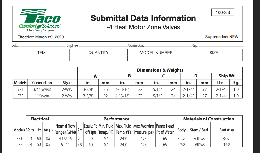
Something seems odd about the Taco 571/ 572.
The 3/4" 571 shows 6 Cv, 20' of pipe equiv.
But the larger 1" 572 with a 7 Cv show 60' of pipe equiv.
That seems like a big difference?
 Bob "hot rod" Rohr
trainer for Caleffi NA
Living the hydronic dream0 -
OP here…. (some answers…)
—> What am I trying to solve? it seemed that certain areas of the house were warmer when we had the 110 in-line circ. The furnace and circ were replaced in 1999. I do not know the size of the old furnace unfortunately. The 1999 SlantFin is AGA Input=175,000 D.O.E. capacity = 145,000. I=BR capacity = 126,000. Otherwise I'm trying to answer the question, "do I really have the proper circulator"?
—> 441 equiv. feet seems like alot..? (Please see my attached diagram and read the text on that posting; it should explain, or depict everything. The issue on that downstairs loop, is that the furnace is on one side of the house, and one of the loops goes to the other end of the house.. it just takes alot of pipe-feet to do that… All tubing is copper pipe, of the depicted size (see diagram)—> I can go thru my calc again, if someone can tell me how many feet of head a given length of 3/4inch copper gives, and a given length of 1" and a given length of 1 1/4 pipe gives. This will probably result in lower head numbers.0 -
@e070924 said " it seemed that certain areas of the house were warmer when we had the 110 in-line circ. "
Then I'll repeat my observation that the Taco 110 pump curve goes to zero gpm at a max of 7.5 feet of head. So if the system worked better with the Taco 110, that was with a circulator that was adding less than 8 feet of head, at most.
I'll also repeat the observation that the Taco 007 actually has a higher max head of about 10 feet, and therefore has a higher flow rate than the 110 at a given head for lower flow rates, up to about 12 gpm where their curves cross.
So if the system worked well with the Taco 110, there's no reason it shouldn't work with the 007, unless the piping was changed.
0 -
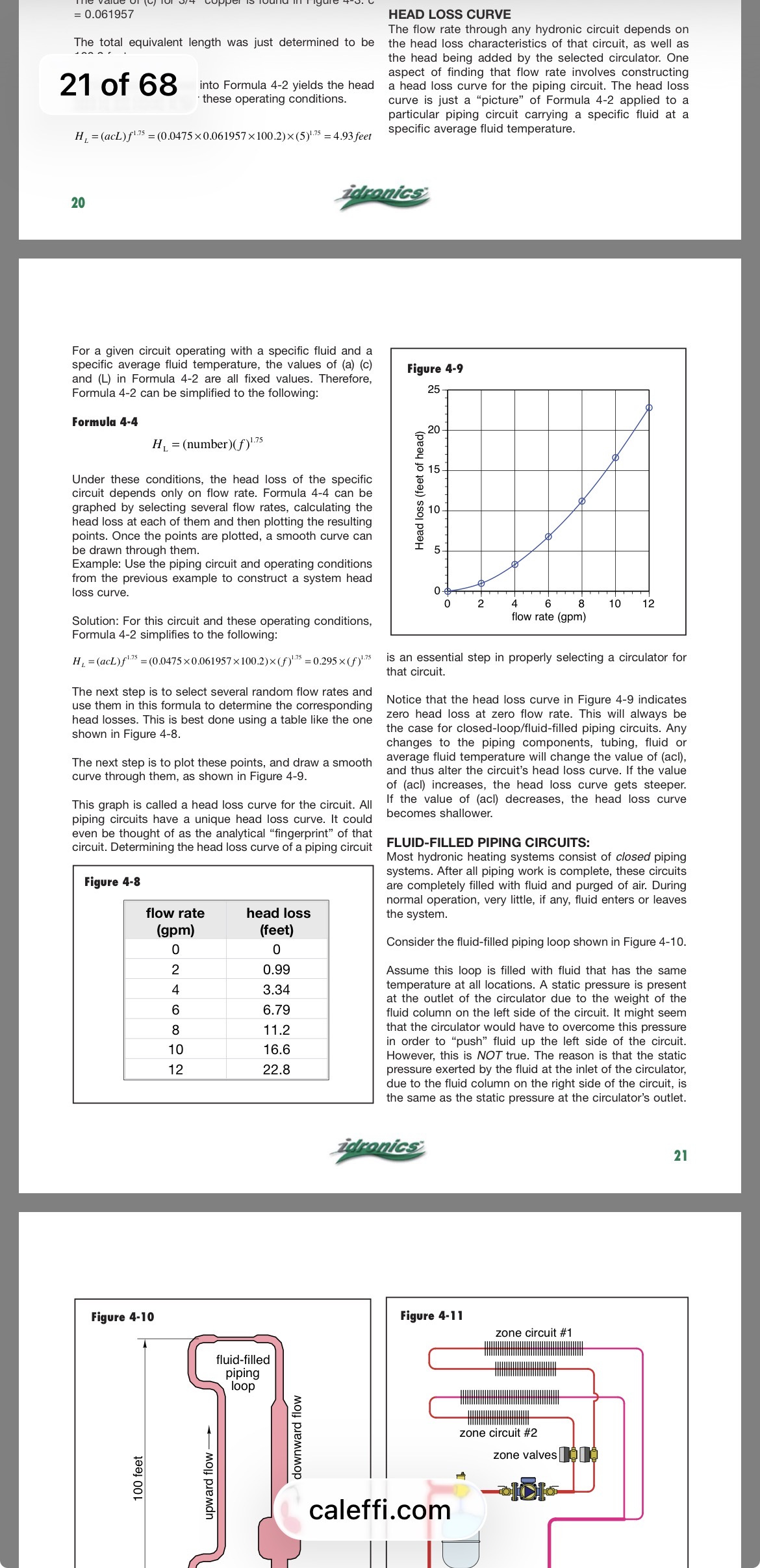
the flow resistance in a pipe, a circuit changes with flow rate. Either 3/4 copper tube 4 gpm is about all you way to flow
Idronics 16 takes you through a circuit analysis along with a typical system example
Fig 4-8 gives you the pressure drop formula tor various flow rates
2-4 is most common in hydronic design
Too slow and air does not move with the flow. To fast and the piping gets velocity noise,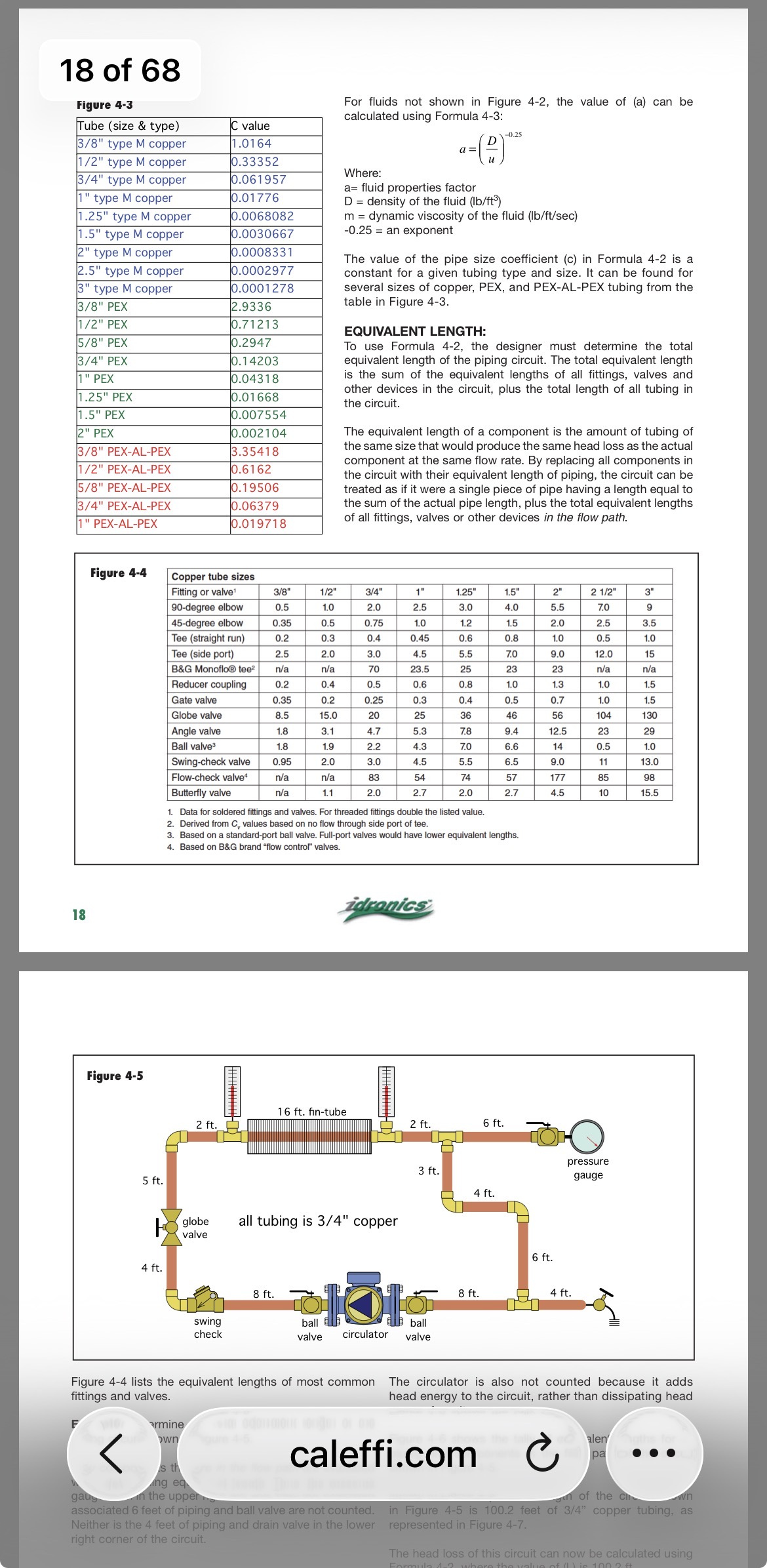
 Bob "hot rod" Rohr
trainer for Caleffi NA
Living the hydronic dream0 -
I'm ging to ask a pretty dumb question. I honestly can't make out from the discussion how this thing is piped. I get that there are two zones. OK. But. Are they series piped — that is, the outlet from each bit of radiation is the inlet to the next? Are the zones home run? Are they parallel return? Are they reverse return? Might they even be monoflow?
I've held off commenting on this thread, because I simply can't answer the fundamental question you are asking — why are some areas warmer than others? — without knowing how the piping runs.
I don't think your problems have anything to do with the head and flow characteristics of the pumps.
Sketch or diagram, please.
Br. Jamie, osb
Building superintendent/caretaker, 7200 sq. ft. historic house museum with dependencies in New England0 -
I will repeat what I have been saying and that is almost every boiler has an 007. Think back a few months and think about all the "service calls" we get on this forum where the op complains of lack of heat and yup they are running an 007. Particularly with Monoflow systems they don't seem to work well.
0 -
Here's an old thread with a two-loop Monoflo system where the OP complained of insufficient heat upstairs. There was a lot of discussion as to whether his Grundfoss 15-58 3-speed was adequate or not. One HH'er said he always had "good luck" using Taco 008's on Monoflo systems.
0 -
Jamie Hall - I'll produce another diagram that is a more 'physical' diagram versus logical.. I'll answer the questions about how its piped, and how the 'loops' are connected from the boiler-output into the return manifold. Thanks, all - stay tuned…
0 -
You don't add all your pressure drops together to come out to a total head loss. you only have to be able to overcome the largest one. If you can move the water thru the highest resistance loop then you can get flow thru the others as there resistance will be less. You add the GPM's so you have enough moving when all zones are calling.
0 -
What your really going to have a problem with is balancing the system. You have a split loop with multiple paths on each loop. You need to ensure proper flow thru each loop or some loops are gonna get more flow than others. You need circuit setters or similar devices on the loops for balancing. Obviously the accuracy of your drawing is going to play a major factor in getting the correct replies
0 -
we may have overlooked OP not worried about static pressure, you need to have enough static to fill to the highest rad, plus 5, or all bets are off, (or I misunderstood , , , )
"—>I didn't bother with Static Head to get up to the 2nd floor, because this is a closed-loop, and what-goes-up, must-come-down,"
known to beat dead horses0 -
OP is correct that you don't account for "lift" in a pressurized closed loop hydronic system, given the cold static pressure is adequate. I suppose we have all made an assumption their static fill pressure is adequate given that they mention accounting for the closed loop when most who don't deal with circs every day would think their circ has to "lift" water up the house.
0


Categories
- All Categories
- 87.7K THE MAIN WALL
- 3.3K A-C, Heat Pumps & Refrigeration
- 59 Biomass
- 430 Carbon Monoxide Awareness
- 129 Chimneys & Flues
- 2.2K Domestic Hot Water
- 5.9K Gas Heating
- 122 Geothermal
- 170 Indoor-Air Quality
- 3.8K Oil Heating
- 79 Pipe Deterioration
- 1.1K Plumbing
- 6.6K Radiant Heating
- 396 Solar
- 16K Strictly Steam
- 3.5K Thermostats and Controls
- 56 Water Quality
- 51 Industry Classes
- 51 Job Opportunities
- 17 Recall Announcements