3-way valve plumbed correctly?

This question has been on my mind for years…
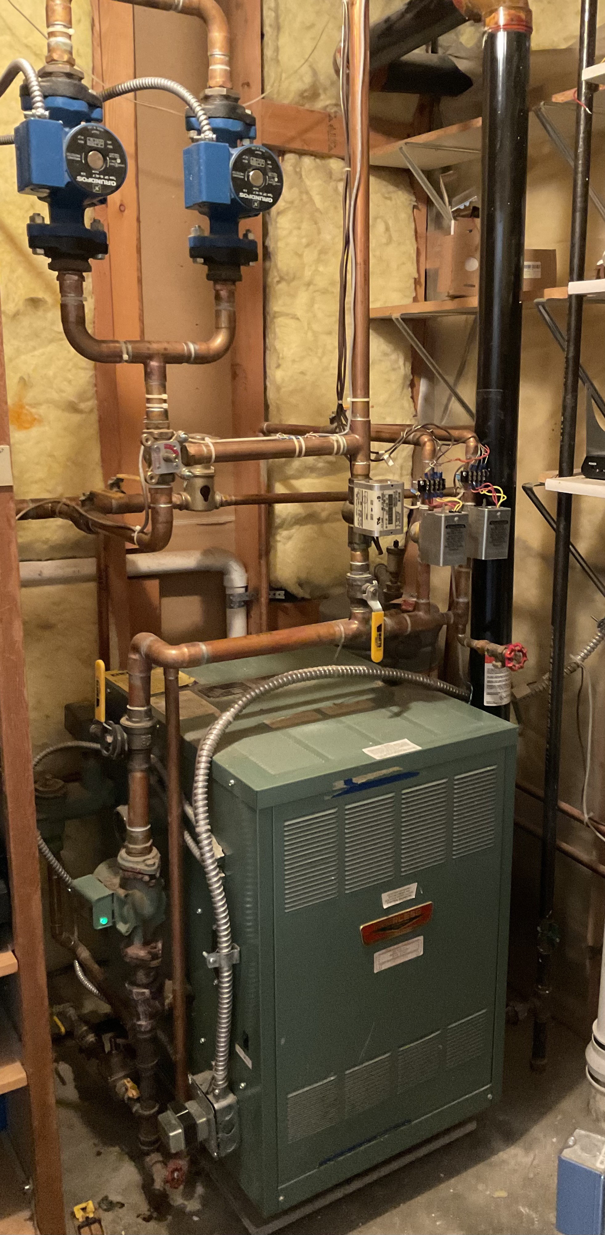
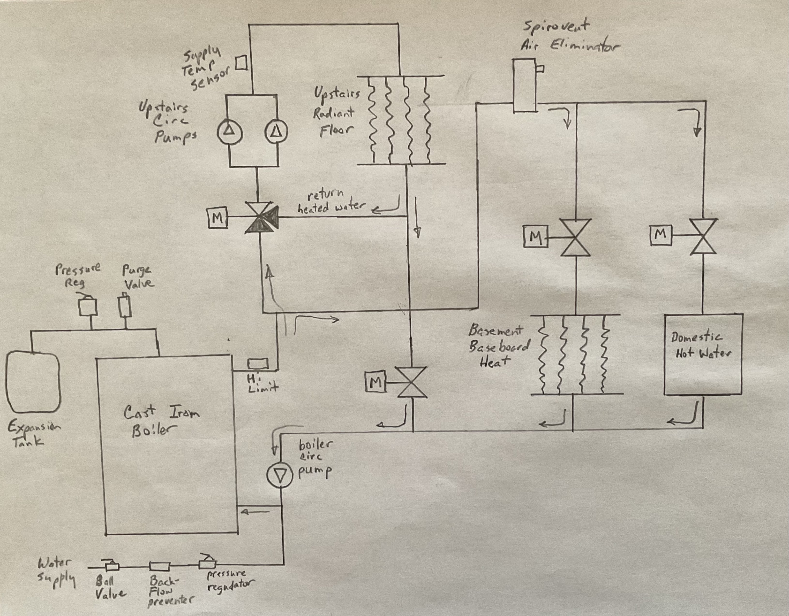
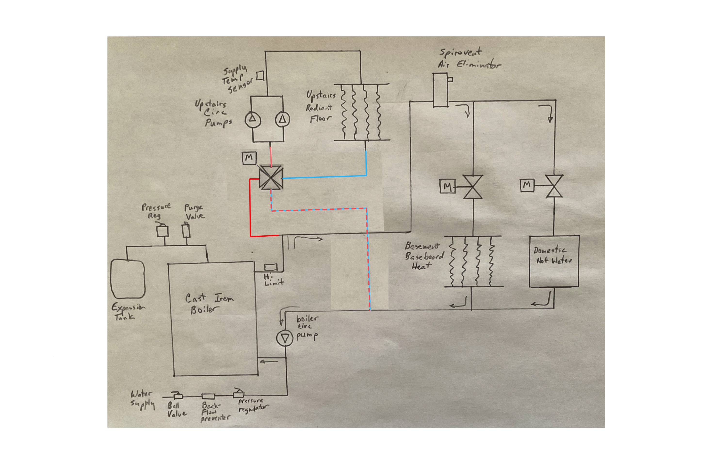
My house was built in 1993, we purchased it in 1996 (30 years ago). We have 3 heating loops: radiant floor heat upstairs, baseboard heat downstairs and a domestic hot water tank. Heated water is supplied by a cast iron boiler. We have been very happy with our system and it has been operating fine. My understanding of this system has slowly increased over the years.
We need to supply fully heated water (~160F) for our basement baseboard heaters and the domestic water heater, but we’d like the water temperature of our upstairs loop to be lower (~140F or lower) since we have hardwood floors upstairs. Our upstairs radiant floor heating is controlled by a Danfoss ECL9304.
My question: is the 3-way valve the proper valve to be used in this system? When the upstairs radiant floor is in steady state and doesn’t have much need for makeup heat from the boiler (and there is no call for heat from the basement baseboard loop or the domestic hot water loop), the 3 way valve is adjusted to the point where the water from the boiler is nearly shut off—most of the circulating water comes from the upstairs return branch. My belief is that this causes undue pressure inside the boiler because the boiler circulation pump is on the return side, pushing water through the boiler.
It seems that a 4-way valve would be much preferred here—it would allow two loops to operate independently—the upstairs circulation pumps would supply heat to the upstairs radiant floor and the boiler circulation pump would run water through the boiler. The amount of mixing would be adjustable and no high pressure would be present.
I really don’t want to tear into this system to make any unnecessary modifications. It’s been working just fine the way it is, but I worry about decreasing the life of the system or increasing the probability of a leak in the boiler operating it this way. But maybe this is a normal design. I’d appreciate the advice from the experts on this forum.
Photo and schematic supplied below. I’ve removed the Danfoss motor from the 3-way valve in the photo.
Thanks!
Comments
-
Assuming that your diagram is correct — and why shouldn't it be?! — the only thing amiss at all is that the expansion tank should really be on the inlet line to the boiler circulation pump as should the connection with the backflow preventer and all that. But — the way it is is OK. As to the pressure in the boiler — that's controlled in your setup by the expansion tank, and what happens when the boiler circulating pump runs is that the pump REDUCES the pressure on its inlet side which PULLS the water through the rest of the system and eventually out of the boiler!
Br. Jamie, osb
Building superintendent/caretaker, 7200 sq. ft. historic house museum with dependencies in New England0 -
I see your point on this if all the red lines were closed valves.
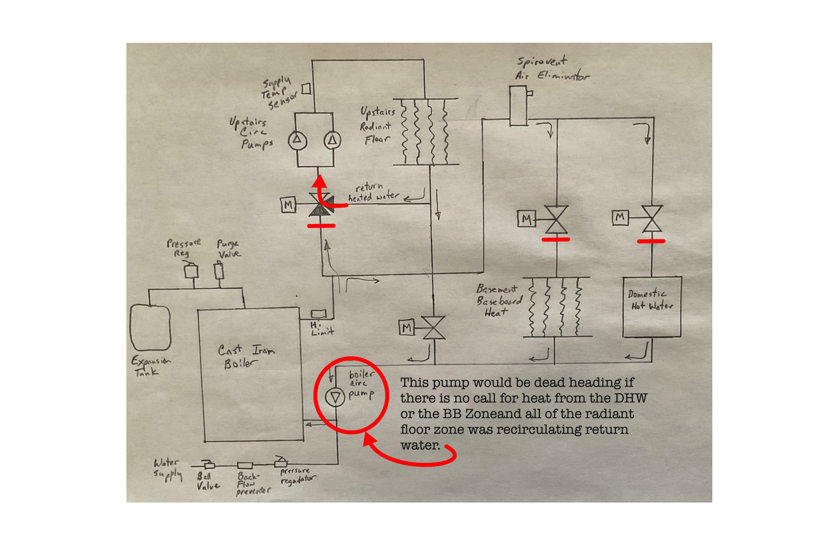
The thing is… that does not happen very often if at all. the return water from the radiant loop will always be lower that the water coming out of the mixed port of the three way valve. That means that there will always be some hot boiler water being added. So the 3 way will always have some small flow thru the boiler in order to keep the boiler circulator from dead heading. If you were experiencing this problem, you would have been replacing that boiler circulator on a regular basis over the last 30 years.
Edward Young Retired
After you make that expensive repair and you still have the same problem, What will you check next?
0 -
It's not quite a primary secondary piping which would be the best way to pipe a two temperature system.
o
Bob "hot rod" Rohr
trainer for Caleffi NA
Living the hydronic dream0 -
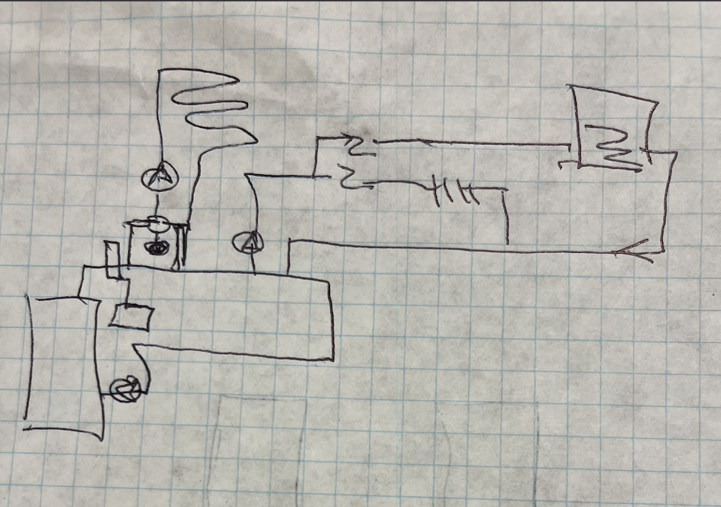
I wonder if this arrangement would be acceptable Bob @hot_rod?
The zone valve for the radiant floor zone is not necessary. Save if for a future repair on the other two zones. A 4 way valve will allow the boiler pump to keep pumping a non restricted amount of water when the radiant zone is mostly recirculating return water from the floor loops. The same motor can be used for the 4 way valve if you can find the 4 way valve that uses that motor. This might be the lowest cost, easiest repipe available for you, if you feel the need to make that change after 30 years of operation.
Have you been having problems with that circulator failing?
Edward Young Retired
After you make that expensive repair and you still have the same problem, What will you check next?
0 -
If anything, I would rather see you pipe it P/S. Then you could keep using that mix valve.
Just converting to a 4 way give you a path back to the boiler, but puts the boiler pump in series with the radiant pumps when the high temp loads are off.
As Ed mentioned if it has worked well for 30 years, is it worth the $$ Repipe and upgrade when that boiler gives up. Unless is has other issues? I suspect the boiler short cycles when 1 or two zones are on, so efficiency may be in the 70% range?
When the day comes, a mod con would modulate nicely to the various loads, be sized exactly to the load, and operating in 90% condensing mode for some of the season
Does the Danfoss operator still work? Is it connected to a to a reset controller ?
Bob "hot rod" Rohr
trainer for Caleffi NA
Living the hydronic dream 1
1 -
Why two parallel pumps? Double the GPM?
8.33 lbs./gal. x 60 min./hr. x 20°ΔT = 10,000 BTU's/hour
Two btu per sq ft for degree difference for a slab0 -
Thanks for all the helpful comments. Here are some answers and some additional information…
Ed, your modification using a 4-way valve is what I had in mind as well.
Alan, I’ve pondered why there are two pumps in parallel as well. Note: only one was powered when I moved in and I’ve been running with one all these years. Maybe redundancy? Or maybe the designer was unsure about how much flow he’d actually need? Things seem to be fine running one of the two pumps. I get a 10 degree F drop from supply to return water. Does that seem about right?
Bob, the Primary/Secondary Piping looks interesting. From your sketch it looks like I’d need a new pump on the high temp circuit.
I didn’t tell the entire story before… The system did originally use a Danfoss ECL9304 with reset control. But a few (5?) years ago the ‘castle nut’ cracked and I lost the ability to control the 3-way automatically and I’ve just set its position manually. We’ve been getting by using this approach, but I’ve tended to leave the upstairs supply temperature close to the boiler temperature ( too warm). But now we’re getting our solid maple floors upstairs refinished and I’m interested in protecting the newly finished floors. The wood floor seems to have survived the warmer temperature just fine, but I want to run our floors at a lower (and actively controlled) temperature.
I’m a retired electrical engineer. I’ve been frustrated with the Danfoss controller in that it “makes decisions” regarding it’s settings and provides little information about the temperature measurements it’s basing those decisions on. I’ve got our boiler system well instrumented—probably 12 temperature sensors—I can access pretty much any temperature you’d want to know in the system digitally, including the outside temperature. I’m comfortable with the idea of designing a custom controller.
Question:
Now that you understand what I’m facing, can you suggest a good resource for learning more about how to properly design this system? I’m considering John Siegenthaler’s “Modern Hydronic Heating”, but man—it’s expensive. I’d purchase it if I knew it was the right resource. I’m looking for a book that will explain concepts like Primary/Secondary loop design, closely spaced Tees, “mod con”, and other aspects regarding how to design a good hydronic system for my particular application without becoming an expert myself.
It’s either a new book, or I’ll keep coming back and asking questions on this forum.😜
I appreciate your help!
0 -
I should let you know that I live in Northern Colorado, north of Denver. It’s been warm and dry here all winter. Much unlike the weather they’re experiencing in the north-east!
0 -
As a homeowner designing and installing my own system I have found tremendous value in the Idronics series of magazines (Google it) from Caleffi and Youtube videos from Caleffi and Taco. Both are on line and free. I also have Siegenthaler’s book. The other sources cover most of my questions but the lack of a comprehensive index requires one to look a bit harder harder for the answer.
0 -
i would just add a differential bypass valve between the supply and return. Primary secondary would be better but there are a lot of things that would be better here but most of it is currently good enough and not worth dealing with until you need to replace the boiler.
The 2 circulators in parallel probably have to do with making loops that were too long and needing more head to get the needed flow. If one isn't working you should either replace it or block it off, unless it has an integral flow check the water will mostly flow through that circulator back to the inlet of the working circulator rather than through the loop.
you can get an actuator you can control for that mixing valve. or replace it with a mechanical thermostatic mixing valve if you don't want to use outdoor reset.
like @hot_rod said it is likely to short cycle, that can possibly be reduced by holding off on re-firing the boiler longer when only the radiant is calling. A buffer tank or mod con is the real fix but that will cost far more than it will save so that is something to do when you have to replace the boiler.
Modern hydronic heating would be good for you. You can buy older editions used for not a whole lot and for what you need you don't need the current edition. Caleffi's Idronics is also good but doesn't always dig as deeply in to the calculations but is good for what products to use.
0 -
if those circs are piped parallel then gpm is doubled not the head, do it is a bit of a head scratcher. If they are able to be isolated one could be a piped in spare?
 Bob "hot rod" Rohr
trainer for Caleffi NA
Living the hydronic dream1 -
i didn't word it right but you will get a certain flow at a certain resistance and with 2 you will get more flow with that same resistance, but you would need more flow because the resistance was pushing you to the left side of the pump curve.
0 -
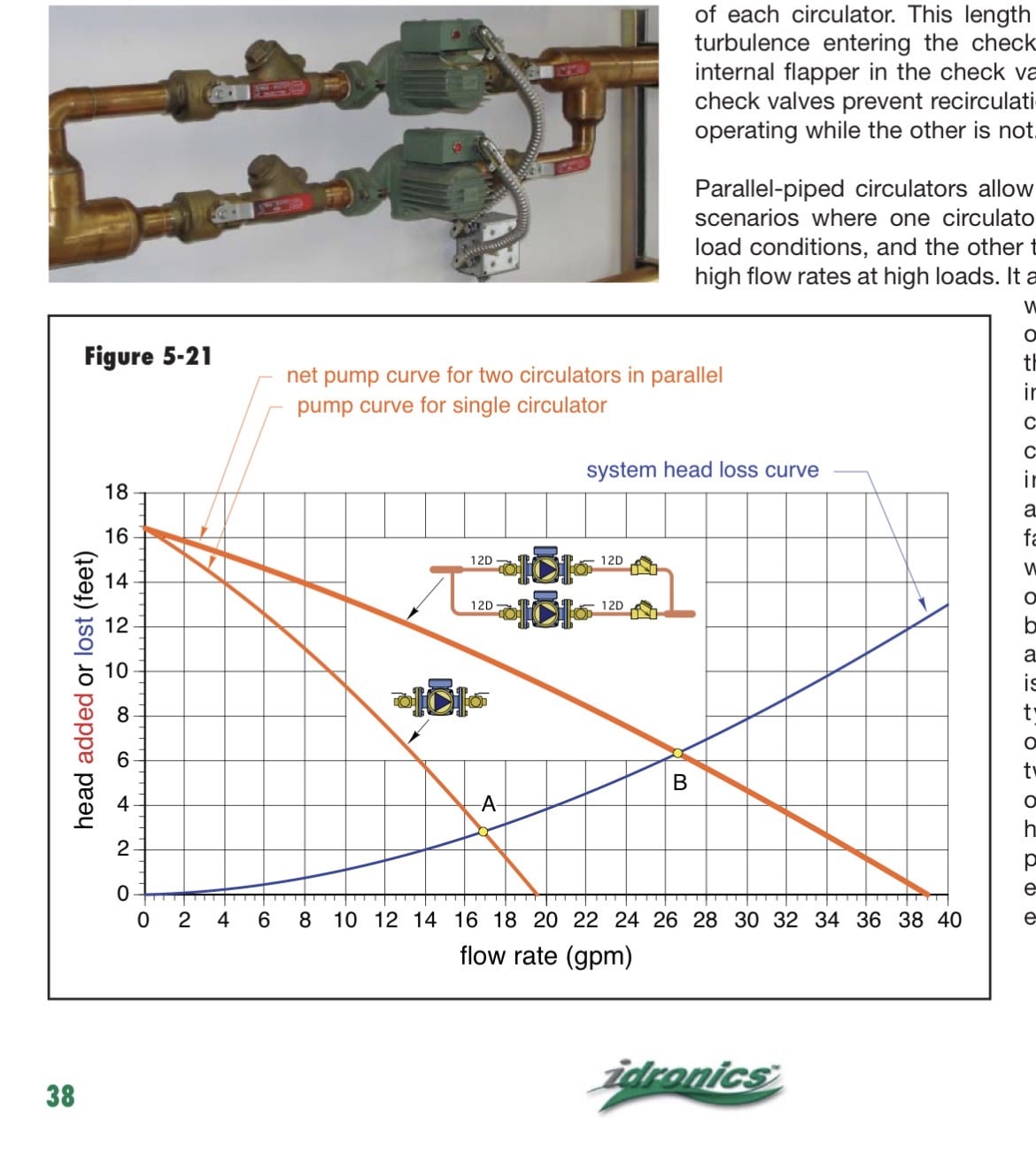
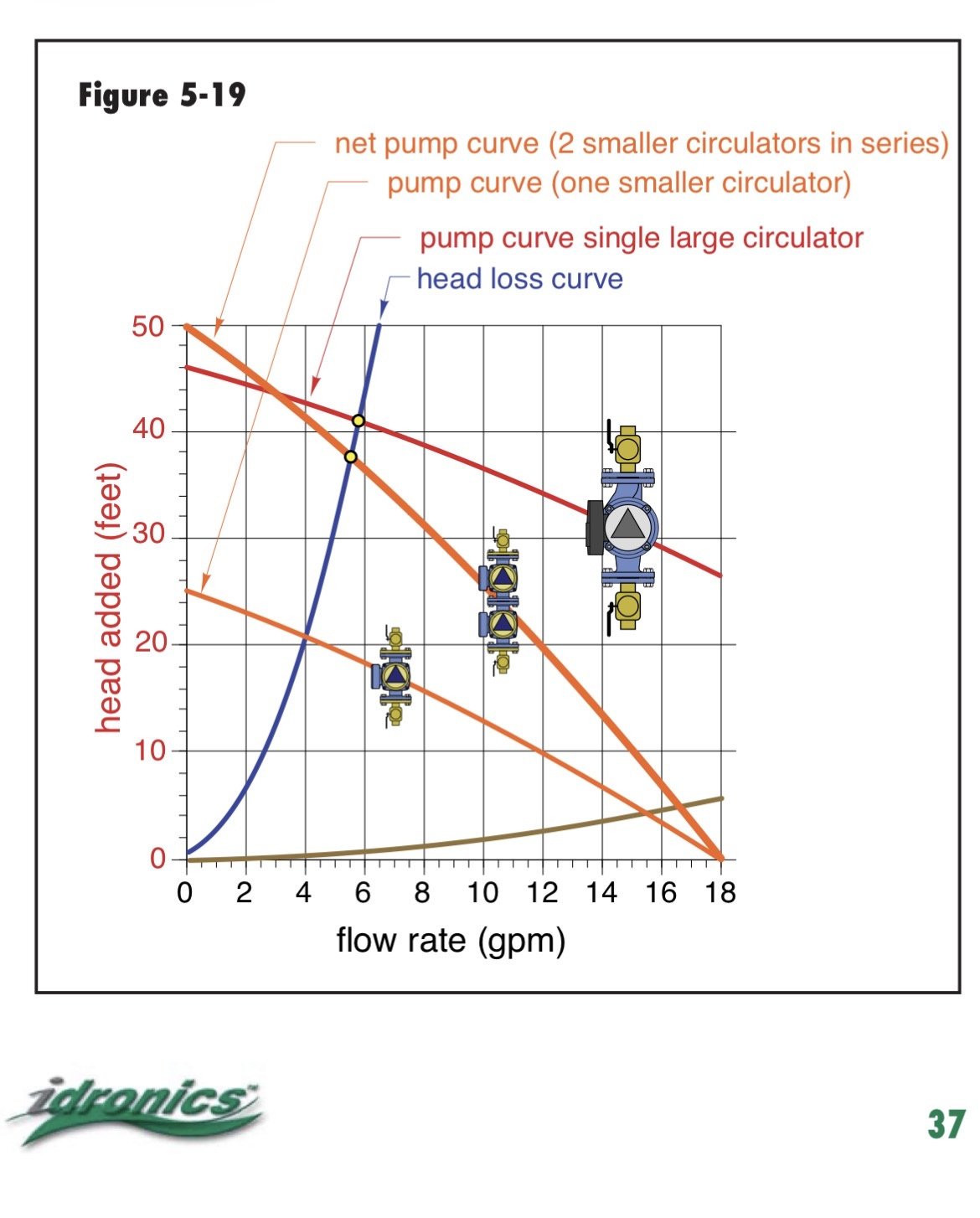
The exact answer would be determined by putting the system curve over the pump curve. The blue line in the example is an arbitrarily system curve just to show the concept
This example shows two identical circs in series. So at shutoff head, 0 gpm flow , top left of the curve the head is doubled
 Bob "hot rod" Rohr
trainer for Caleffi NA
Living the hydronic dream0


Categories
- All Categories
- 87.7K THE MAIN WALL
- 3.3K A-C, Heat Pumps & Refrigeration
- 59 Biomass
- 430 Carbon Monoxide Awareness
- 129 Chimneys & Flues
- 2.2K Domestic Hot Water
- 5.9K Gas Heating
- 122 Geothermal
- 170 Indoor-Air Quality
- 3.8K Oil Heating
- 79 Pipe Deterioration
- 1.1K Plumbing
- 6.6K Radiant Heating
- 396 Solar
- 16K Strictly Steam
- 3.5K Thermostats and Controls
- 56 Water Quality
- 51 Industry Classes
- 51 Job Opportunities
- 17 Recall Announcements