Alpine 105 Sage 2 Controller replaced
Comments
-
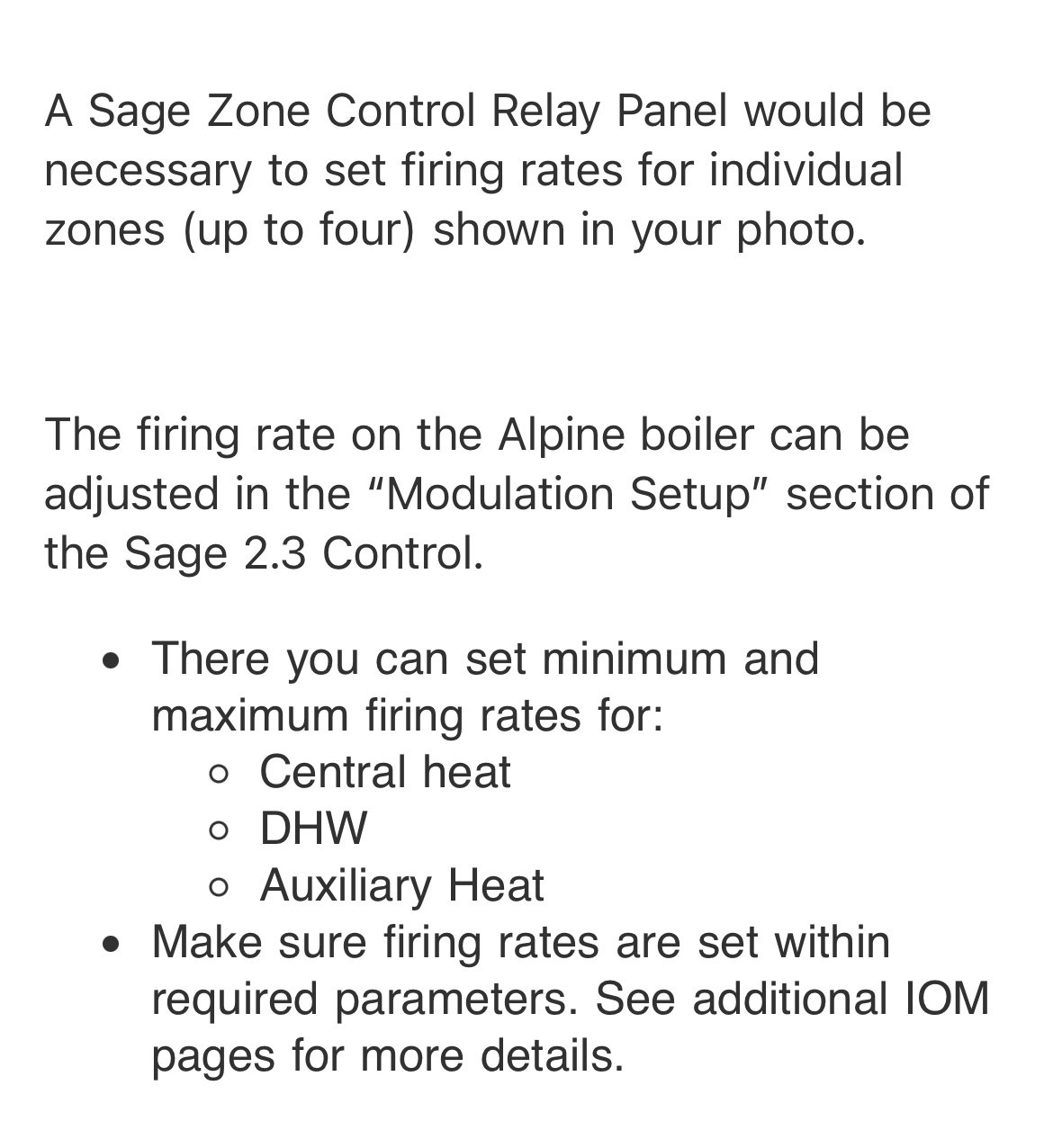
yes, there’s a modulation s/u screen. The available variables are set as follows:
- min 1250 rpm
- max DHW 4000
- max central heat 4850 rpm
I read the instructions for the mixing valve and also expected to see 110 deg. I thought maybe since the radiant wasn’t calling for heat that the manifolds drifted to room temp, but in hindsight that’s probably not logical if the (bathrooms) were warm.0 -
so my questions would be
Why is there a mixing valve?
Is the mixing valve running ODR and the boiler running ODR?
It looks like 5 loops of pex, is that the total heating load on the boiler?
If so 5x .5 gpm per loop is 2.5 gpm, or approximately a 25,000 btu/ hr load connected
It that is the case you would want to derate the boiler from 105, down to max 25,000 if that is possible. Most mod cons are 10-1 turndown, so yours should modulate down to 15,000 btu/hr
We need to make sure the version of the control and the manual match up.
Is the new control you installed a newer version?
I would want to make sure we have the correct manual and then determine what parameters are available for you to access.
Some boiler controls need a password to access installer programming, which opens more options. My Lochinvar has a User and Installer access. Not much programming is available in User mode.
probably call a U.S. Boiler rep to answer that and if the zone controller needs to be connected to open the parameter #10 that I showed above
Bob "hot rod" Rohr
trainer for Caleffi NA
Living the hydronic dream0 -
I can’t answer why there’s a mixing valve. I didn’t design the system. I thought the general use of the valve was to improve efficiency of the system. Given the cost of the valve ($500+) I’d be surprised if it was installed but not needed (but you never know…).
There are four radiant loops Two operate with a single thermostat (kitchen - hardwood floor) and 1 each for two bathrooms. The boiler is also used for the indirect HW tank. The installer sized the boiler for up to 8 zones (manifolds are 8 zones) for future expansion (house has 5 bathrooms).The Sage controller that was failing was a 2.1 I installed a 2.3. The 2.1 was not the original that came with the boiler.
I’ll have to investigate the ODR and report back tomorrow.When adjusting parameters I need to log in with the contractor passcode. User access is “read only”.
Since I’ve been round and round through the screens I can access, I’m guessing that the lack of a zone controller is why I cant access parameter 10.
0 -
I have a call in to a U.S. boiler rep that I know. I’ll see what he can clear up
Maybe you need the Heat Match software to access some settings?
You would pick up some efficiency by piping without the mix valve and let the boiler modulate on ODR and the step fire function. But that would take some repiping
 Bob "hot rod" Rohr
trainer for Caleffi NA
Living the hydronic dream0 -
 Bob "hot rod" Rohr
trainer for Caleffi NA
Living the hydronic dream0 -
You’re not looking for a “parameter 10”. That was a section heading in the boiler manual. The original settings sheet you wrote out includes a “Modulation Setup”. Look there.
Typically a mix valve would not be used unless you wanted to run two temperatures: one for the hardwood and maybe another for tile. But the would require some modifications of the piping. Maybe originally this was expected, but then the plans changed?
Check to see if you have an outdoor temperature sensor connected to the boiler. It’s better to disable the mix valve and use the boiler settings for temperature control directly in this case.0 -
I’ve already described all of the adjustable parameters in the modulation s/u section. There are 3:
- min (1250 RPM)
- max DHW (4000 RPM)
- max Central Heat (4850 RPM)That’s all I can access from the front panel of the Alpine. I’m using the password protected “adjust” access to look through the software settings.
I checked this morning - yes, outdoor temp sensor installed. It is wired to BOTH the mixing valve and the boiler. If needed I can detail the wiring (it’s a bit of a jumble of low voltage wiring twisted together). There’s also a wire that runs from the mixing valve to a union, that I’m guessing is a thermocouple? It’s placed immediately after the circulator for the radiant.
When the system was installed only 1 bathroom had been piped for radiant, with future zones TBD.
0 -
I would adjust the max rpm down until it reads around 30,000 btu/hr, I don't know what rpm that will be.
The boiler and the I-valve would need to have individual sensors mounted outside, on a north wall, they could not share a sensor.
I'm not sure how two outdoor reset control behave with one another. I would prefer the boiler adjusts based on ODR, if saving fuel and increasing efficiency is the goal.
I could be the i-valve is targeting one temperature, the boiler another temperature, based on how the two are adjusted?
Bob "hot rod" Rohr
trainer for Caleffi NA
Living the hydronic dream0 -
I’m reluctant to start adjusting the RPM down without a clear understanding of how it will impact the boilers operation. If I begin to lower it, what changes should I expect to see? How would I know when I’ve gotten to the optimal setting? How would I know when I’ve gone too low? I feel like I’m flying in the fog with no radar.
0 -
You would either want to know the heatload of the building and adjust the boiler output to that.
Or just try a few different settings.
An analogy, how far down do you depress you accelerator when driving? The same for the boiler, lowering the RPM, lowers the horsepower.
You wouldn't floor your accelerator and use the brakes to control your speed??
So running the boiler to full power for a load that is a fraction of the HP wastes fuel, shortens component life, is annoying to hear it going on and off every 8 minutes, etc.
There is no exact answer, my suggestion is limit the heating output of the boiler to 50%. Does the home maintain temperature on a cold day r night. If so lower it another 5%
The manufacturer puts all those settings and parameters in the control so the user or installer can adjust the boiler to the specific job. You paid for them, may as well use them.
Bob "hot rod" Rohr
trainer for Caleffi NA
Living the hydronic dream0 -
I thought I’d trace out the low voltage mixing valve wiring to better understand how everything operates. I found what is likely an issue.
The valve has two strap on sensors (Taco 9300-2044) that I’ll ignore.
The outdoor sensor has two conductors: one Green (G) and one Blue (B).
The G is connected (wire nut) to a Red ® wire that runs to the mixing valve. Let’s call this wire nut “N” and I’ll come back to it in a minute.
The B also runs to the mixing valve (wire nut - white (W) wire to the valve) and also has a B wire that goes to a terminal strip of the boiler. The terminal strip is immediately behind the front panel of the pull out tray to the far right. The terminal strip connection location says “DHW sensor/outdoor sensor).
There’s also a G wire connected to the location of the terminal strip immediately below the B wire. The term strip label says “outdoor sensor”. This G wire runs back to the wire nut N mentioned above where the G outdoor sensor wire and R mixing valve wire are connected. It’s stripped and looks like it might have popped out of the wire nut.
The other wire nut (the B-B-W) connection is very close by, but the position of the green wire (and color) tells me it should be connected to “N”.
I should also mention that there are lots of other stripped wires just twisted back and not connected to anything as the cable was 4 conductor with only 2 conductors used.I’m thinking I’ll power the unit down, connect the green wire @ “N” and power back up.
Make sense?
0 -
correction: location of the power strip is behind the pull out tray in the LEFT corner.
0 -
If it were me I pull the actuator of the mixing valve, move it to full open. Assure the boiler ODR is connected and working and let the boiler do the thinking. I think you have 2 conflicting controls at work.
Spend your time and energy on getting the boiler parameters dialed in. There should be an outdoor sensor.
Even if you ball up a setting there is probably a "return to factory setting" overide that takes you back to square 1.
Running a mod con to 150 to mix it down to 110 for the radiant makes no sense at all. To me anyways.
Unless there is a zone that requires 150 supply temperature?
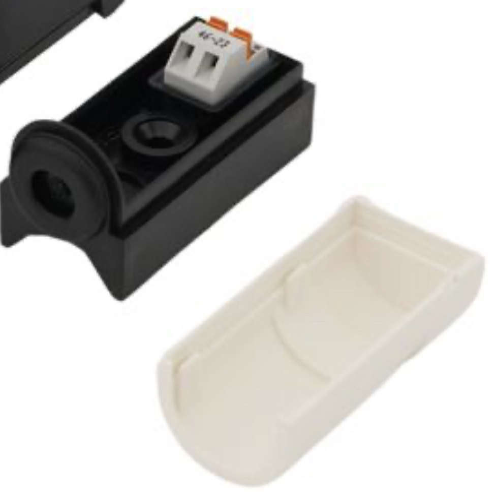
The Alpine outdoor sensors look like this.
You might check US boiler website or search You Tube for a U S Boiler Sage 2.3 programming video.
 Bob "hot rod" Rohr
trainer for Caleffi NA
Living the hydronic dream0 -
@Slowhand63 Regarding the outdoor sensor wiring:
The sensor is a 10Kohm thermistor. It is a variable resistor that changes it's resistance depending on the temperature. I am not an electronics guru, but I advise you to only connect it to the mix valve, or to the boiler. But not both. Here is my reasoning. Inside both the mix valve and boiler, there is an electronic system that needs to determine the resistance through the outdoor thermistor sensor. There are different ways this can be accomplished. I do not know how the mix valve does it. And I do not know how the boiler does it. It is quite possible the two methods will interfere with each other or even damage each other. Perhaps someone that knows more about these electronic systems will comment.
@hot_rod wants to skip ahead.
Disconnect the sensor from the mix valve and wire it into the Alpine instead. (They both use 10kohm thermistors.) The boiler will be aware of the connected sensor and you should be able to see the current outdoor temperature in one of the details screens.
The mix valve should be configured as hot_rod described above.
0 -
Thanks to both of you for the suggestions. My plan will be to disconnect the low voltage wiring from the mixing valve, connect the outdoor sensor to the Alpine, and see what it tells me. After a bit I’ll begin to reduce the RPM on the Central Heat from 4850 - first to 4000, then to 3600 and then 3200. I’ll report what I see as I go.
Re setting the mixing valve in the fully open position - I’ll have to research how to do that. I assume I can turn the large black dial on the actuator clockwise until it stops?
I have to travel for work and won’t be back until Tuesday or Wednesday. Unfortunately I’ll need to wait to then until I make the above changes. Hopefully you’ll both be able to re-engage once I have some additional information. I really appreciate all of the guidance to this point. 1
1 -
That's fine. You have the right idea now.
I don't know why they put a mix valve in the system. Maybe they were worried about the wood floors expanding and contracting as the boiler cycles on and off? It would make sense if you had a more traditional high mass boiler. But a modcon like yours should regulate well enough by itself for this application, I would think.
0 -
I think with power disconnected from the mix valve you can manually turn it to hot. I think it is basically a 3 way ball valve with a motor actuator.
Bob "hot rod" Rohr
trainer for Caleffi NA
Living the hydronic dream0 -
I think I've done all I can do at this point. I swapped the outdoor sensor so that its connected to the Alpine instead of the mixing valve. I've lowered the Central Heat max RPM from 4800 to 4000. The boiler continues to cycle constantly (when reaching max setpt it moves to postpurge, the temp drops quickly and within a minute or two another cycle is initiated) and the cycles seem to be running longer. Not sure if that's a good thing or if I'm simply burning more and more gas.
I don't think I see any other change in operation, nor do I really know at this point what I'm looking for (other than less frequent cycling).
I think I'm at the point where I need to call in a professional and review the operation of the entire system. I'm developing a comprehensive list of things to review and get guidance on (boiler setpts, circulator speeds, mixing valve vs. boiler modulation, etc. etc.). It could take a week or two (?) to get someone here, but once I do if I learn anything I will certainly post the findings. The boiler is also groaning on startup, so I may perform a full service and replace the blower (I have a spare) to see if I can resolve that before I have a tech come in.
If there are any recommendations for a good tech in the NY area, I'm all ears.
Thanks to everyone who engaged with this thread and offered advice. It is greatly appreciated.
0 -
Do you have the mix valve open? And what temperature is the boiler targeting now that the outdoor reset is enabled?
0 -
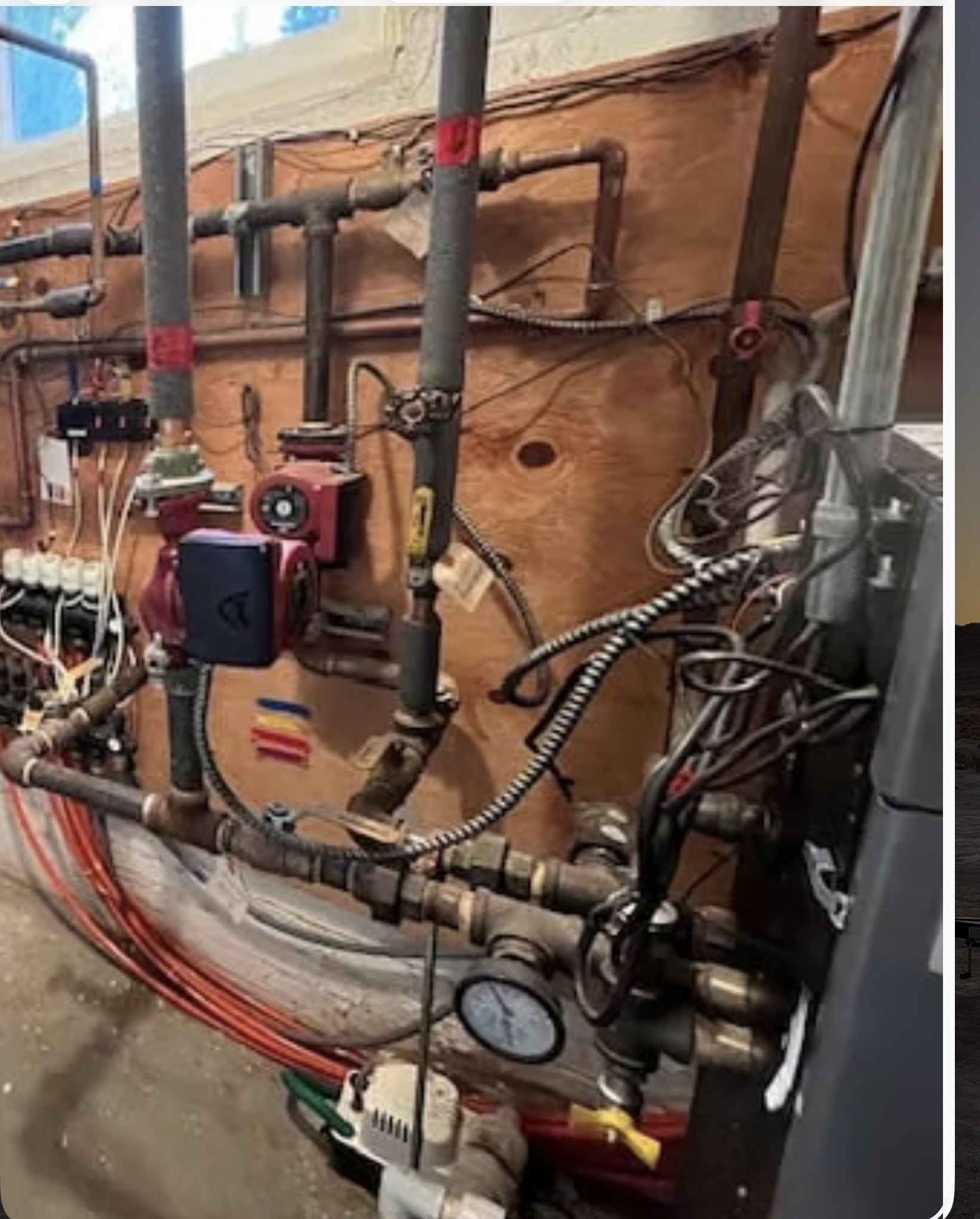
now it is starting to sound like inadequate flow through the boiler. Maybe a piping issue or air lock
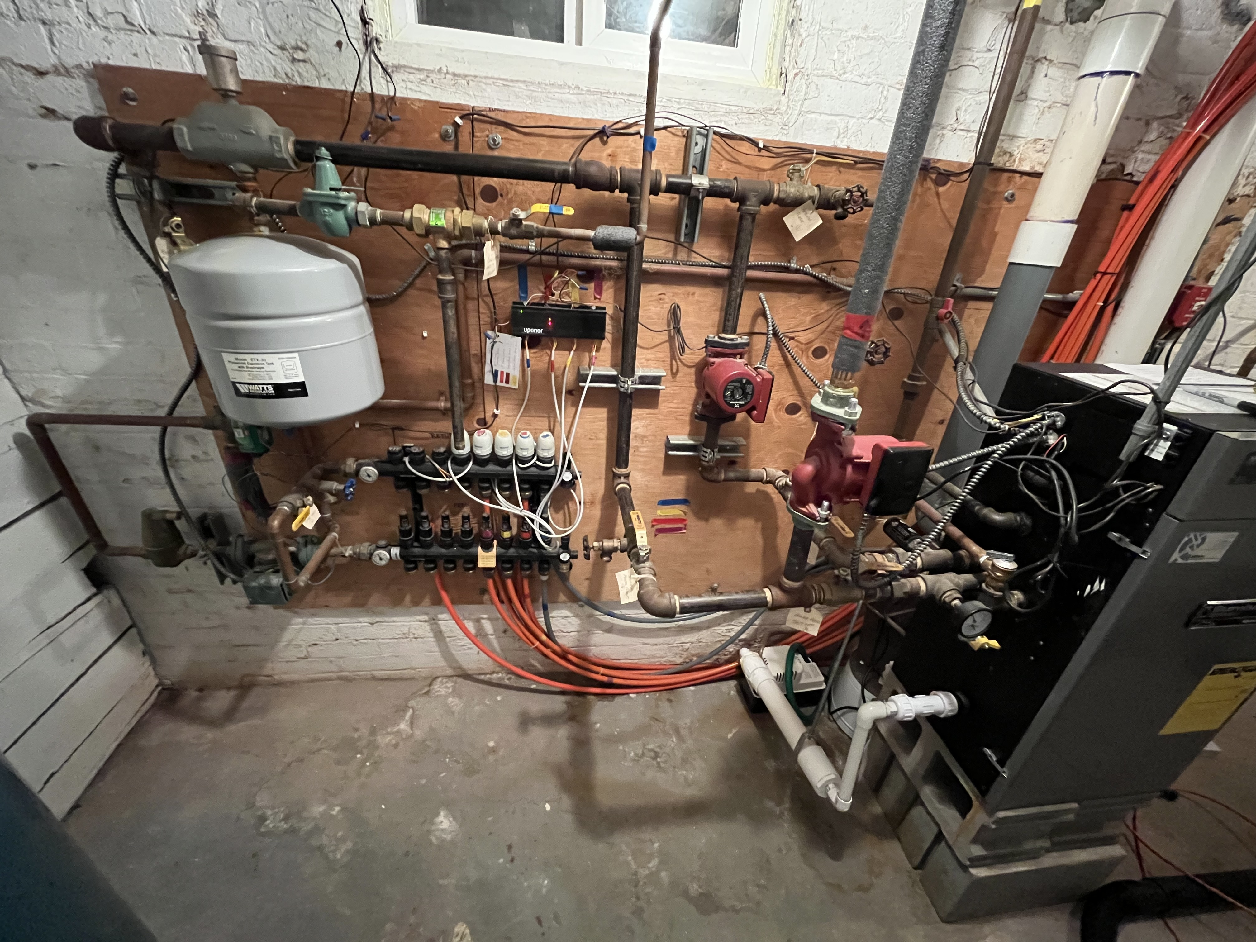
That is a water tube type of boiler and it needs a dedicated circulator and primary secondary piping.
I can’t see enough of the piping to see if it is piped correctly. Or maybe add a sketch of the piping.
 Bob "hot rod" Rohr
trainer for Caleffi NA
Living the hydronic dream0 -
Eastman - I’ve made no additional changes to the boiler programming. Both DHW and Central Heat have a setpt of 170 deg.
Re the mix valve - it may not be fully open. What do I do to ensure it’s open?
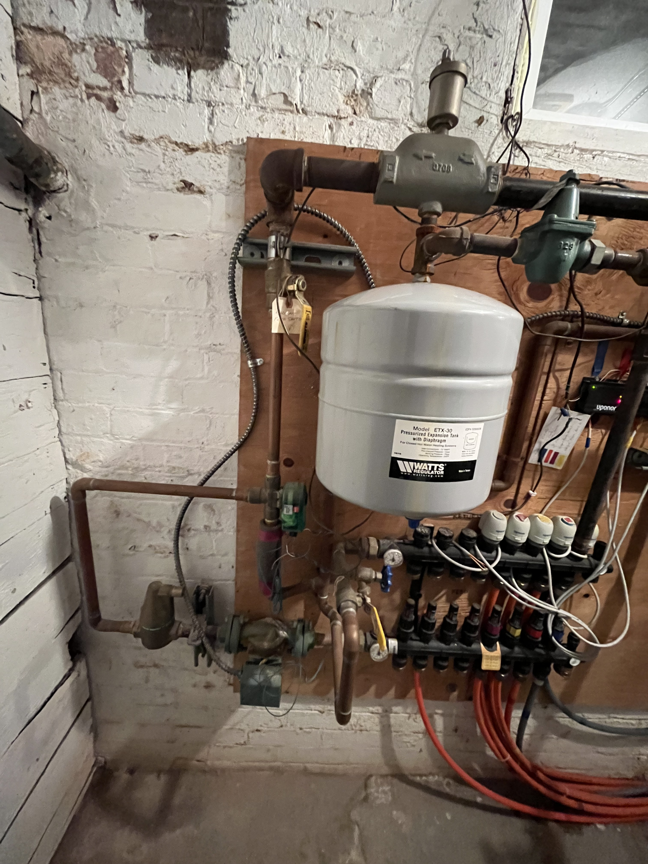
Hotrod - I’ll see if I can post a couple of additional photos showing the piping.
I should note that I’m a little concerned about the mixing valve being disconnected, since my understanding was that one of the functions it performs is to prevent the boiler temp from getting too low (below 135 deg).0 -
you have a condensing boiler so the lower the return the better they like it, and efficiency goes up.
Return temperature concerns is for non condensing style boilers, like cast iron.
With power disconnected you should be able to turn the mix valve all the way to hot
The valve manual tell you how to turn the valve manually. With the actuator off a pliers may be needed to turn the valve full hot
 Bob "hot rod" Rohr
trainer for Caleffi NA
Living the hydronic dream0 -
 0
0 -
I think this is accurate…
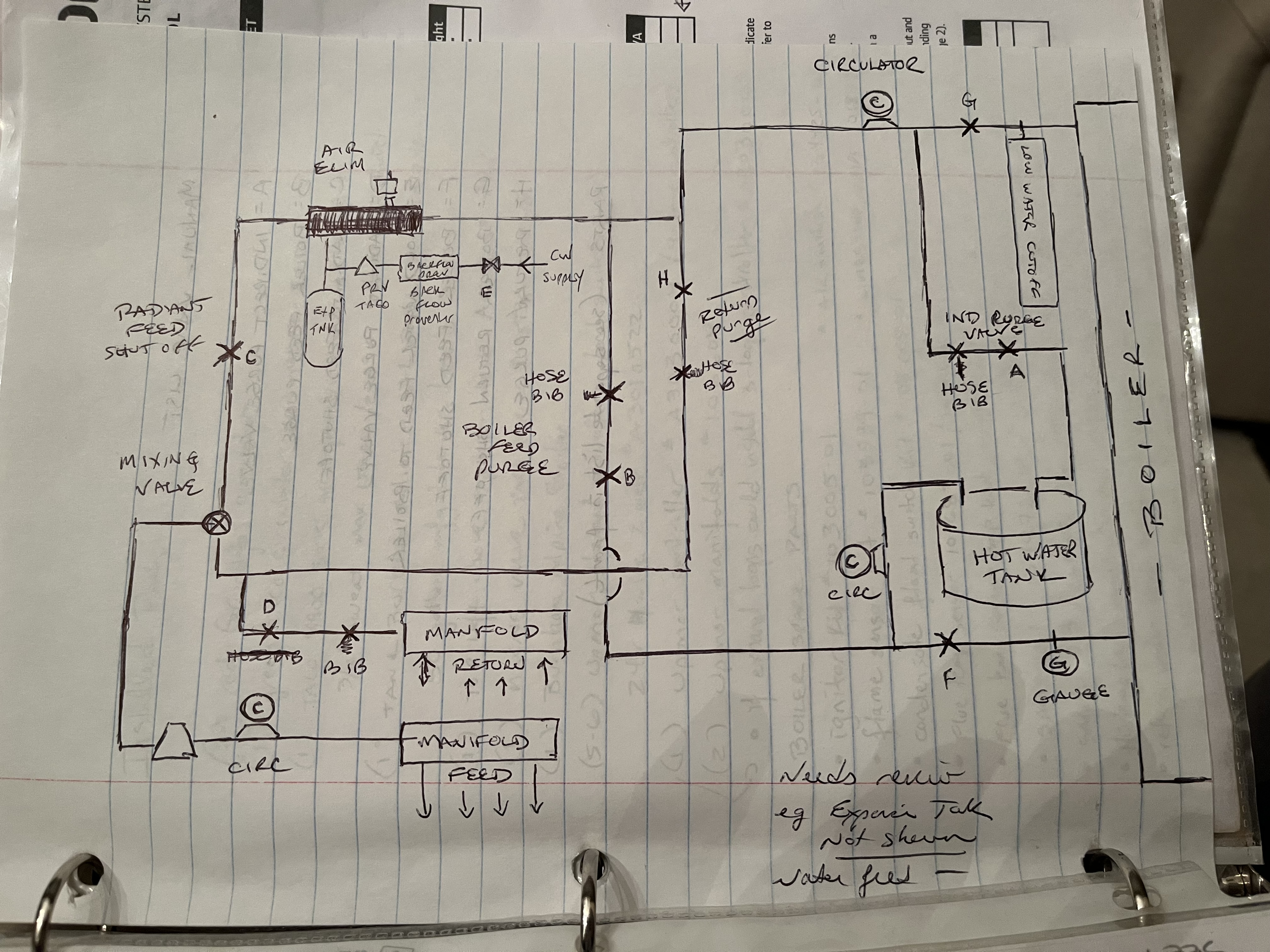 0
0 -
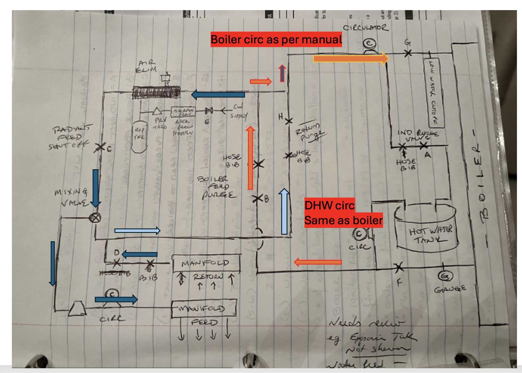
If this is the case, I see aloop thru the boiler, with an odd use of tees, but it should flow. Then the blue arrows are the system loop. Red arrows are the boiler loop
The boiler pump needs to be sized per the manual, 105K and larger need a Grundfos 26-99 I believe
Them indirect pump needs to be that size also to assure the boiler coil and tank gets adequate flow.
I would turn down the boiler firing (rpm/ btu/hr) limit on the control even more, see if that helps.
I only see 4 loops of radiant? 4 X .5 gpm/ loop= 2 gpm or around 20,000 btu/hr is about what those tubes can move, so I suspect the boiler output could be cranked down as low as 25,000 btu/hr.
No harm in trying to crank it down, what do you have to lose?
 Bob "hot rod" Rohr
trainer for Caleffi NA
Living the hydronic dream0 -
Well, you nailed the circulators. They are both indeed Grundfos UPS 26-99’s. The smaller green one near the radiant manifold is a Taco unit (p/n illegible in the photo I have on my phone).
Yes, four loops. Two (small) bathrooms and two loops for a hardwood floor kitchen. Since the direct correlation of RPM to firing rate, how low would you suggest I go? Orig DHW was 4000 and Central Heat was 4800.Also - what does proper operation look like? How should the boiler cycle when calling for heat?
0 -
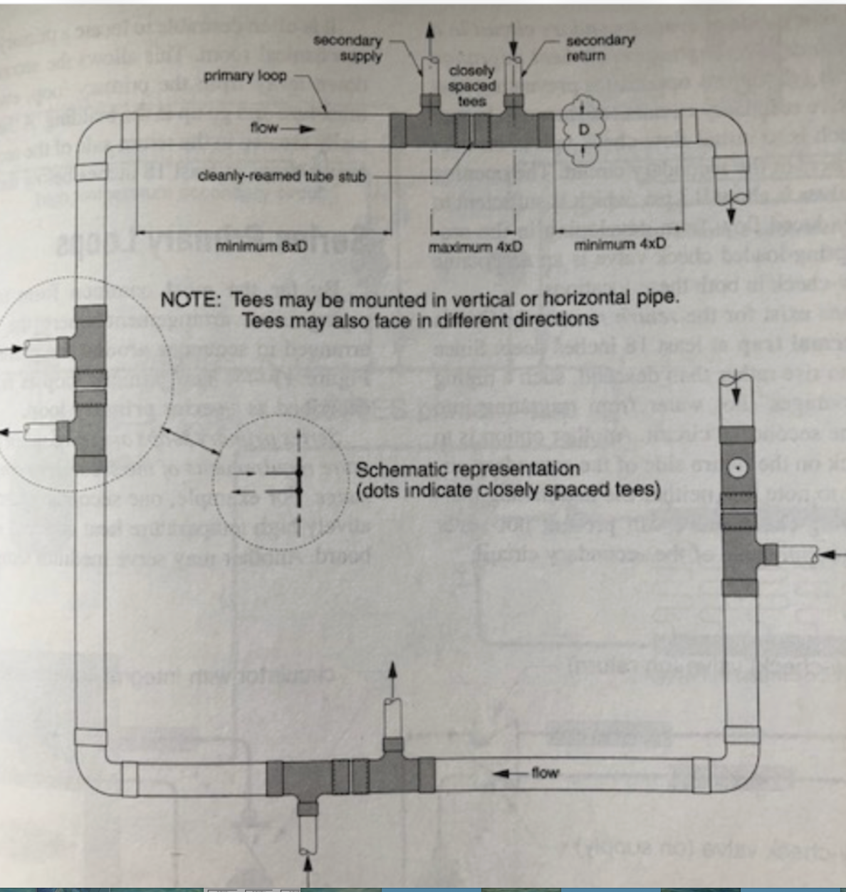
While the P/S piping isn't textbook, I think it should flow okay.
Here is the recommended p/s piping. Tees together with required spacing before and after the tees..
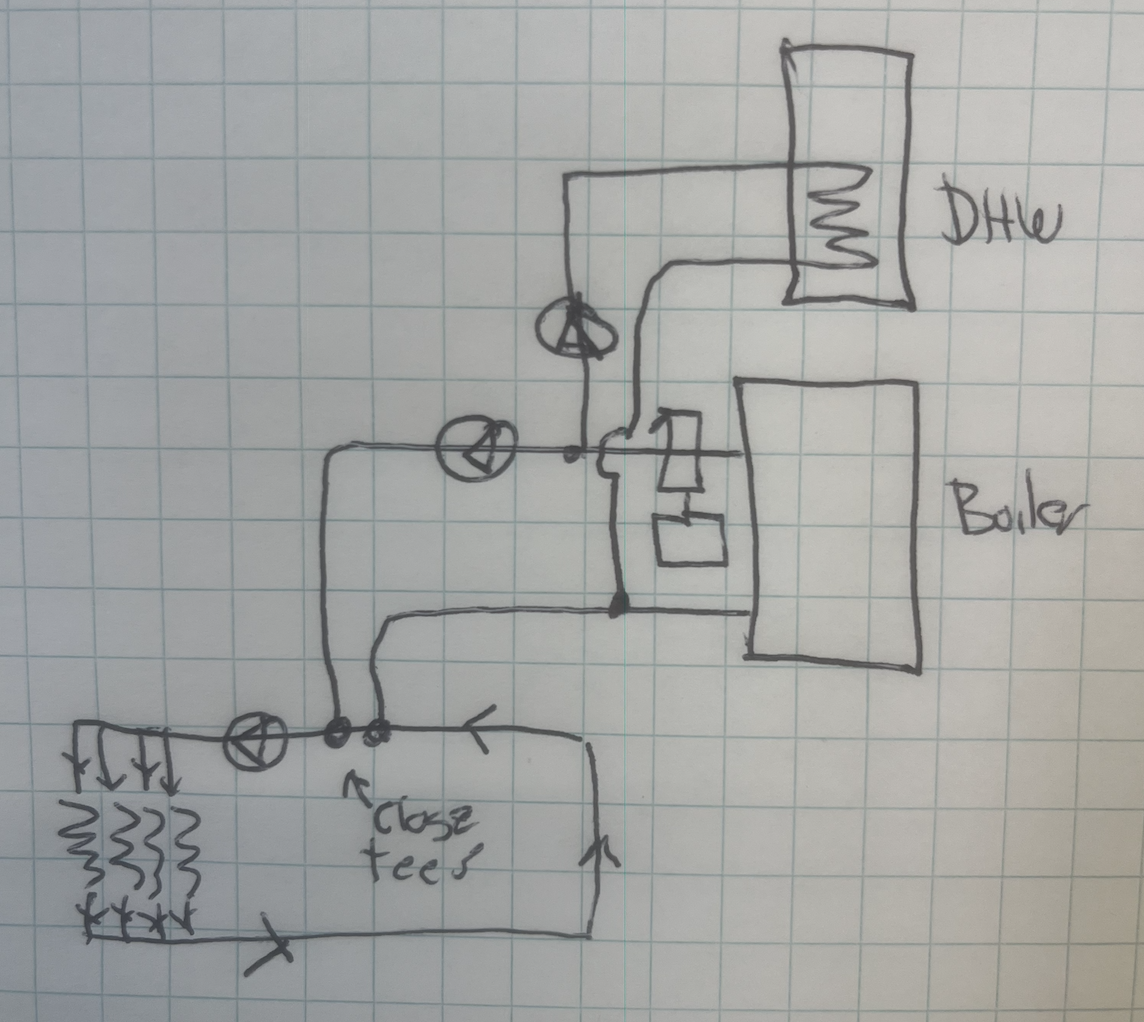
At this point you may not want to repipe, if ever you do, it could look like this. boiler piping just connects to a header with the closely spaced tees.
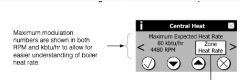
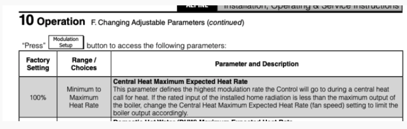
Your controller allows access to this parameter. The Central Heat parameter
Use the down arrow to crank the rpm/ btu down to 1/2 of what it is now. If it is 4480 rpm, take it down to maybe 2500. It should then show what the boiler BTU output will be at that limited RPM, example below.
No need to change any DHW settings, you just want to make the boiler smaller to match the low load.
This should allow the boiler to run longer on cycles. Less on off cycles.
 Bob "hot rod" Rohr
trainer for Caleffi NA
Living the hydronic dream0 -
I wanted to reiterate a few things that hot_rod already touched on:
First, the boiler you have is a newer advanced type that is immune to cold water. Low temperature water returning from the radiant loops and flowing into the boiler will not cause an issue. Rather, it is designed to capitalize on the low temperatures and will actually run slightly more efficiently by condensing some of the combustion gases onto the heat exhanger. This is why the system does not need low return water temperature protection.
Second, the burner on this system modulates. How does that come into play? For starters, most boilers that modulate will allow you to cap the maximum burner output. On this system, the central heat RPM parameter adjust the maximum burner output for calls from the radiant loops. There is also a separate max burner parameter dedicated for domestic hot water calls. Lowering the burner output is kinda like replacing the boiler with a smaller model.
Third, this system is capable of adjusting its target supply water temperature based on the current outdoor temperature. This feature is known as outdoor reset. When outdoor reset is enabled, there is a range of target supply water temperatures. The colder it is outside, the hotter the target temperature. The relationship between the outside temperature and the target water temperature is up to you. There are several parameters for adjustments. The adjustments will generally provide hotter or cooler target water temperatures.
Given the above, the burner will generally cycle as follows:
- There's a call for heat.
- The boiler checks the outdoor temperature and calculates the target water supply temperature. The target is reset to the newly calculated target.
- The boiler asks the question: "Is the supply water already hot enough? Maybe I can ignore the call for heat because the supply water is already close enough to the target water temperature." If the water is already hot enough, the boiler will wait until it's cooled sufficiently.
- Assuming the boiler needs to fire up, the burner will go through its ignition process.
- After the ignition process is complete, the burner will modulate up or down in an effort to produce water at the target temperature. This is where a modulating burner is especially helpful. If the water is close to the target, the burner will throttle back from its maximum allowed rate. But it can only lower the firing rate so much.
What causes cycling? Usually, cycling is caused by thermal energy being added into the water faster than it can leave out into the floor. So energy is building up in the water in the piping and raising the water temperature until it significantly exceeds the target temperature. When the temperature gets too high the boiler will shut down and wait awhile, and then cycle again.
In order to correct this imbalance, we can do a few things:
- Reduce the heat input into the water. Lower the flame. Reduce modulation. Adjust the central heat parameter.
- Increase the heat output from the water into the floor. Heat will flow from the radiant pex into the floor faster if the radiant is operating at higher and higher water temperatures. If you raise the target water supply temperature, energy will leave the water faster.
Keep in mind that a boiler target water temperature works in conjunction with a differential setting. The differential tells the boiler how much it can deviate from the target. The differential provides for a limit above and below the target. If the upper differential is exceeded, the burner will shutdown and the boiler will cycle. A narrow upper differential will cause more cycling. A wide differential will cause more variation in the floor temperature.
0 -
Thanks for the detailed explanation. I'm getting quite an education.
Had some stuff to do today but just went down and adjusted the Central Heat modulation down to 2650. I surfed around in the software a bit and found a couple of interesting things.
Under the system setup, the screen for Outdoor Sensor, "not installed" was selected. I selected "installed" and on the next cycle got an error message for outdoor sensor being open. I changed the parameter back. Reminder that a few days ago I had found that the outdoor sensor was wired to the mixing valve and appeared to have orig been wired to the Alpine ALSO, but it looked like the green wire had pulled out of the wire nut. On your receommendation I pulled the green wire to the mixing valve and connected the green Alpine wire to the sensor. I hadn't noticed that the "outdoor sensor" in the system setup menu was set to not installed. Since the Alpine isn't seeing the sensor, either there's a wiring issue OR the sensor needs replacement. I'll have to look into that tomorrow. I think the sensor is good because it seemed to be working properly with the mixing valve.
After adjusting the Central Heat max modulation to 2650, the boiler still seems to be cycling quickly. It's cycling between 140 & 150 deg, since 150 is the max setpt. The max setpt for DHW is 170 deg. Does 150 seem appropriate? Based on the explanation provided above, I'm thinking that a higher setpt would put more heat into the room and therefore increase the time to the next cycle.
0 -
I think you want to use only the Alpine outdoor sensor, the Taco one may not be compatible. Yes you want a wire that you know is continuous, no breaks or questionable splices
with it connected outside an OHM meter is how you test the sensor. Directions in the manual for that test,
If the boiler quickly ramps up, it indicates that you have low flow or no load. Are all the loops open when you are testing?
did the Taco valve have strainers on H and C ports by any chance? If those are plugged it would limit flow and cause the boiler to ramp up quicklyThe goal here is to match the boilers heat output as close to the heat load or flow that the loops can handle
You can do that by modulating temperature and or modulating flow rate
The boiler has the control go modulated temperature, so that should be easy
You need to assure the entire loop can flow at least 3 gpm. So look for where there could be a blockage Perhaps something is blocking flow in the mix valve
Bob "hot rod" Rohr
trainer for Caleffi NA
Living the hydronic dream0 -
On page 119 of the Alpine manual, various temperature ranges are listed for different applications. You can see that 130 in mild conditions and 160 in cold conditions are recommended for staple-up radiant heating. Every installation is unique, but this general advice is a good starting point. Try 160.
How long does a cycle last? How many per hour? How many calls for heat did the thermostats initiate in the same time period?
0 -
The outdoor sensor looks just like the one you sent me a photo of. I’ll have to look into how to test the sensor with my Fluke.
No idea if the mix valve has strainers. I’m assuming I’d have to remove it to see. I have not removed the actuator and manually adjusted the mix valve to ensure it is fully open. I can’t seem to find the instr sheet from the mix valve (though I know I had it previously). I’ll have to take a look tonight to see if I can figure it out.
I’ll move the Central Heat setpt to 160.
Re calls for heat… I can’t emphasize enough that this is an OLD, leaky cement stucco house that’s poorly insulated (some rooms uninsulated). It’s 15 deg out today. It seems like no matter what at least one zone is calling for heat at any given time. I realize I could turn 3/4 off and get more reliable data. I’m out of the house today and will have to see what data I can pull when I’m home later tonight.
Once again thanks for all of the help. It is very much appreciated!
0 -
You have the Alpine outdoor sensor? You should get roughly 40,000 ohms of resistance using your Fluke with the sensor outside and truly experiencing 15 degrees.
0 -
Okay, one thing at a time.
I found that I inadvertently wired one of the Alpine wires to the Mix valve (as I said before the wiring is a mess). Corrected that and I’m letting it run a bit while I have dinner. After that I’ll check resistance of the sensor, but I’m pretty sure it’s fine and it was my wiring error that caused the error.
I was hoping to get some cycling data tonight (timing runtime and standby when calling for heat) but by the time I get back down there after dinner the sink and shower will be in full use so they’ll be a long DHW call. Probably have to wait until tomorrow.
Oh, and I bumped the Centeal Ht setpt to 160.
0 -
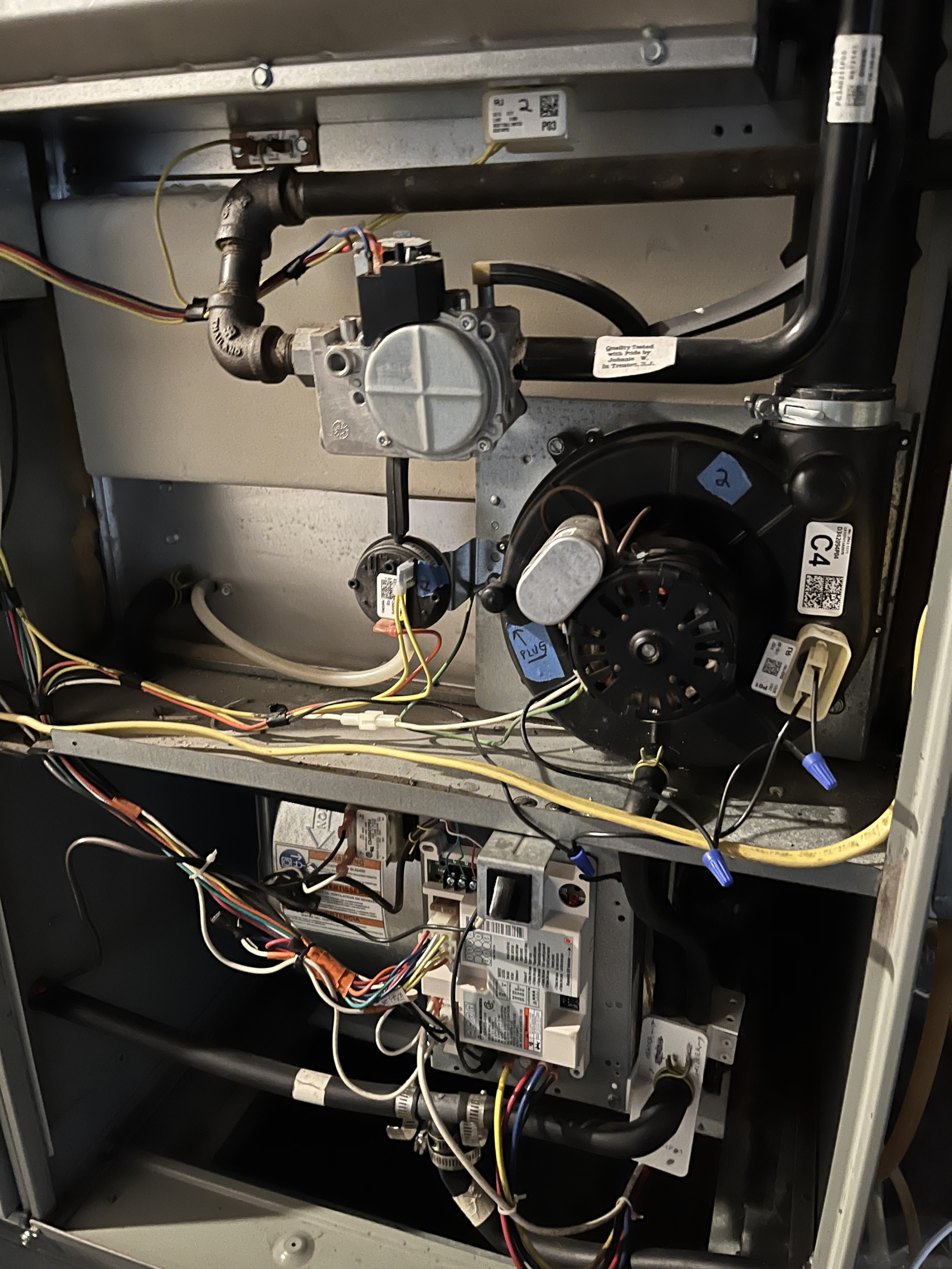
Different day - different unit - different problem.
While down in the basement I noticed a puddle under my furnace today. The s/u of the house is that the Alpine handles the DHW and the radiant. The furnace is two twinned American Standard/Trane 120,000 BTU forced air units that operate as one. Model AUC1D120A9601AD.
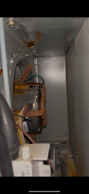
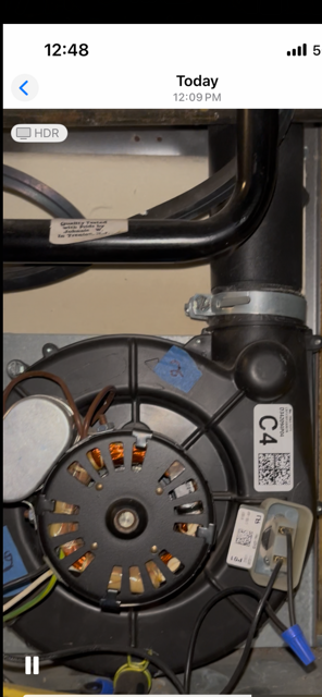
I removed the panel and could see the leak right away. I think its a big issue. It's leaking below and behind where the inducer is mounted - from the heat exchanger? I removed the inducer, all of the associated tubing, and also flushed the white collection box below the inducer where water collects before exiting the furnace. Photos attached. When I removed the tubing there were no signs of a blockage (nothing was "filled" and no water came rushing out).
Yesterday I did another round of shoveling. The 3" exhaust pipes that exit the house are not blocked in any way.
I know I should probably start a separate thread, but since I have your attention helping me address the issues with my Alpine, I thought (hoped?) you might have some familiarity with these units and an idea or two of what I should be looking at.
 0
0 -
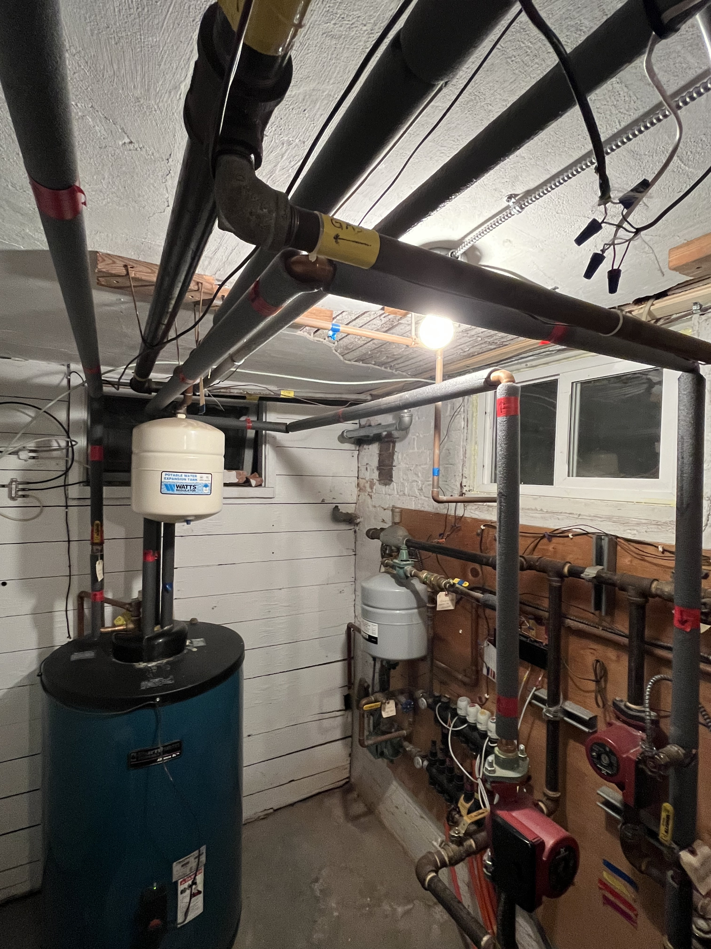
one more photo showing the whole system:
 0
0 -
Sorry, I do nothing with forced air.
0


Categories
- All Categories
- 87.7K THE MAIN WALL
- 3.3K A-C, Heat Pumps & Refrigeration
- 59 Biomass
- 430 Carbon Monoxide Awareness
- 129 Chimneys & Flues
- 2.2K Domestic Hot Water
- 5.9K Gas Heating
- 122 Geothermal
- 170 Indoor-Air Quality
- 3.8K Oil Heating
- 79 Pipe Deterioration
- 1.1K Plumbing
- 6.6K Radiant Heating
- 396 Solar
- 16K Strictly Steam
- 3.5K Thermostats and Controls
- 56 Water Quality
- 51 Industry Classes
- 51 Job Opportunities
- 17 Recall Announcements