Monoflow System
Comments
-
A 120,000 input boiler might have a NET BTUh of about 80,000. so that is the maximum water flow you need. Based on a 20°∆T that would be 8 gallons per minute.
The longest run method for calculating the pump head would use the piping that I outlined in green.
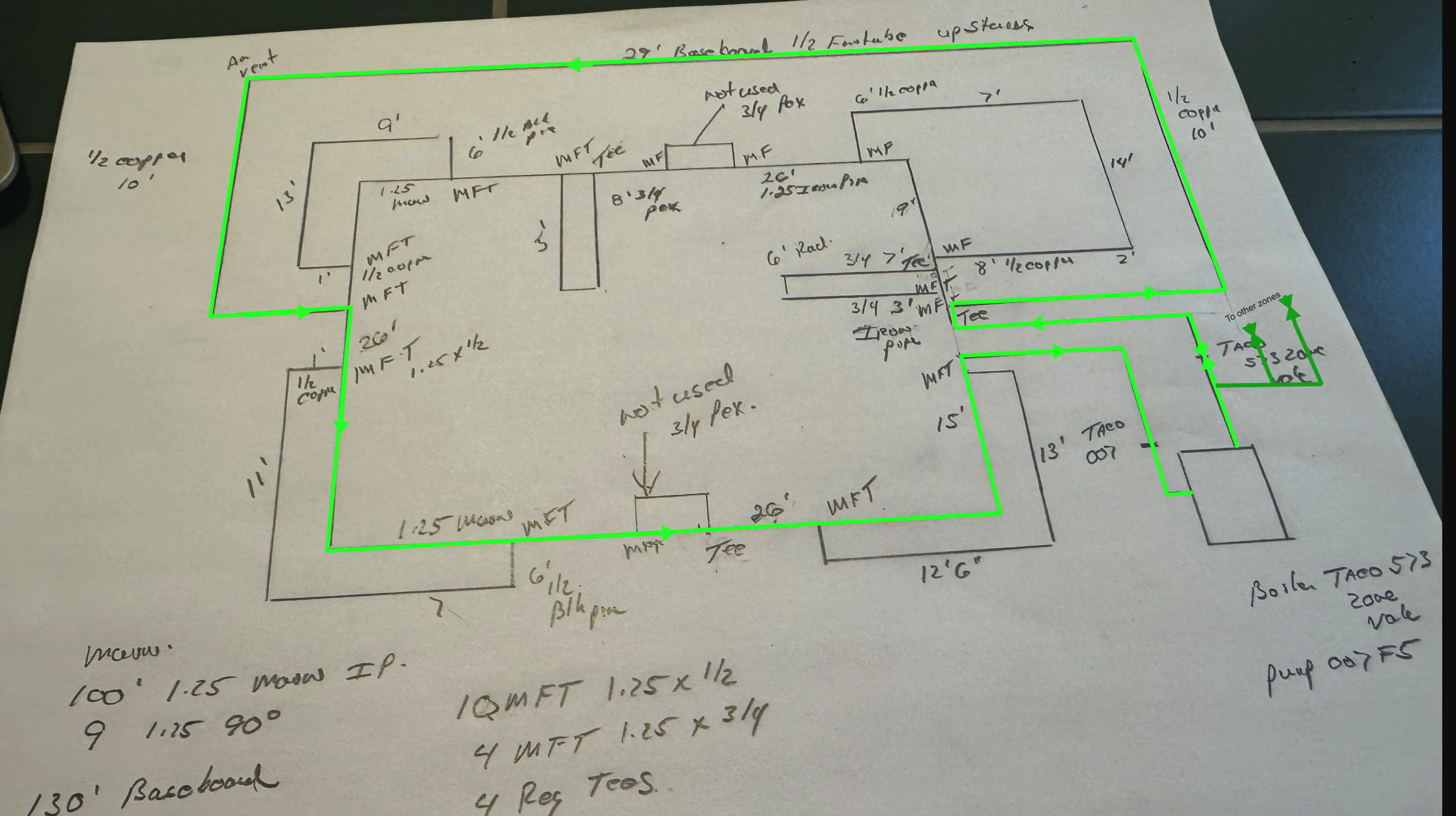
For the MonoFlo® tees that are not used, you have 3/4" PEX labeled I believe that means that there is a short piece of PEX that joined the branch of each Tee in order to allow the full flow thru both the branch and the run of the Tee. Capping off MonoFlo® tees causes a restriction that can not be recovered
From what I can see here you probably have less than 15 ft head at 8 GPM max
Edward Young Retired
After you make that expensive repair and you still have the same problem, What will you check next?
0 -
The other thing thats wrong is the 1/2" sweat stop and waste globe valve. Those are pretty restrictive and also what looks like a balancing valve. So in that picture the flow in the main is going left to right?
The two 1/2" copper lines in the picture are not both second floor pipes are they? Your drawing shows one on the other side of the house?
As far as the tees go they have to be oriented right. They usually have and arrow where it shows which way to orient the tee. When you use them on the supply and return they are reversed.
I don't know why they used tees on the supply and return in some places.
0 -
read what i posted the other day. that baseboard loop with the monoflo tees not sequential is diverting the flow from 3/4 of the first floor. you need more pump but you need to fix that too.
0 -
This is a big problem with the flow? these two are also supply tees in a row?
0 -
So what I would like to do to get the flow back, is take the upstairs baseboard off the main line and make this its own zone with a pump. Remove all monoflow tees that aren't being used for the baseboard heat to lower the head required? The problem in the picture is the 3rd tee you see is the supply for lower right front baseboard heater??? and the return is last on the main 1.25 line?
0 -
The tees are not out of sequence. Some of your "zones" have supply tees and return tees. B & G didn't make supply and return tees. Its the same tee you either orient it one way if its on the return branch and then you turn it around and orient it the other way if it is on the supply branch. Look at the tee it probably has two arrows. One towards the supply and one towards the return. Which way you install the tee depends on if it is used for supply or return.
Hold on a bit I will get this done by the end of tomorrow
0 -
@Skip143727 Is the 120,000 Btu boiler the input or the output?
0 -
Pennco 120,000 input Btu.
0 -
@Skip143727 First of all I would suspect this issue came up as when this was originally installed the 007 pumps hadn't been dreamed of yet. And why wouldn't a service tech stick an 007 in because 'that's what we use in every house" and besides that's what's on the truck. Your original circ was probably a Taco 110 or a B & G 100.
Your baseboard load is only about 70,000 btu which would only need 7ish gpm. Your entire main could have been 1" pipe originally instead of 1 1/4". Since they oversized the pipe you need enough flow to have enough pressure drop across the monoflow tees to drive water through the branch pipes so I used 10 gpm which also fits better with your boiler that is 120,000 input and maybe 90,000 output.
See the attached. I came up with the need for a pump that will deliver 10gpm against a 14' head. This should work although the second floor could still be an issue. I would put the larger pump in and try it. Save the 007 to use for the second floor only in case you want to zone it someday
0 -
So I'm planning on taking the zones valves out and using circulators and removing the upstairs tee to make its own zone. Removing the double tees tied in with PEX not being used there's really no need for them.By doing that, Is it safe to say total head might be 9ft of head at 10 gallons? My concern is the two other basement zones with 3/4 copper and putting the circulators on the supply should help with air removal.
0 -
the zone valve is over 4’ and removing some tees will help soot should get you down to 9’ or so
0 -
I wanna use a taco pumps with a IFC in the pump less fittings? would I need flow checks on the return as well or not needed?
0 -
You shouldn't. But realize if you look at the pump curve for the 007 that 10' is the max head it will pump any water. In fact at 9 3/4 feet it is at shut off head and will pump 0 gpm. If it pumps against no resistance it will pump 23 gpm.
Removing the zone valve will help and it will work better but may not get you where you need to be.
0 -
I was thinking a taco 010 or taco 012 for the 1.25 main and two 007 for the other zones could work right?
0 -
0010 is ok if you take the zone valve out. That would be the best fit.
0012 is borderline with the zone valve
007 fine for the other zones
0 -
All the zone valves are coming out, Would the 012 be too much, i`m thinking that might cover something that I couldn't see or missed. The upstairs I plan on tie that in with 3/4 copper on its own zone and t stat. Sorry for asking a lot of questions.
0 -
This is how the monoflo tees work. The velocity, V of the water is divided by the partition in the tee:
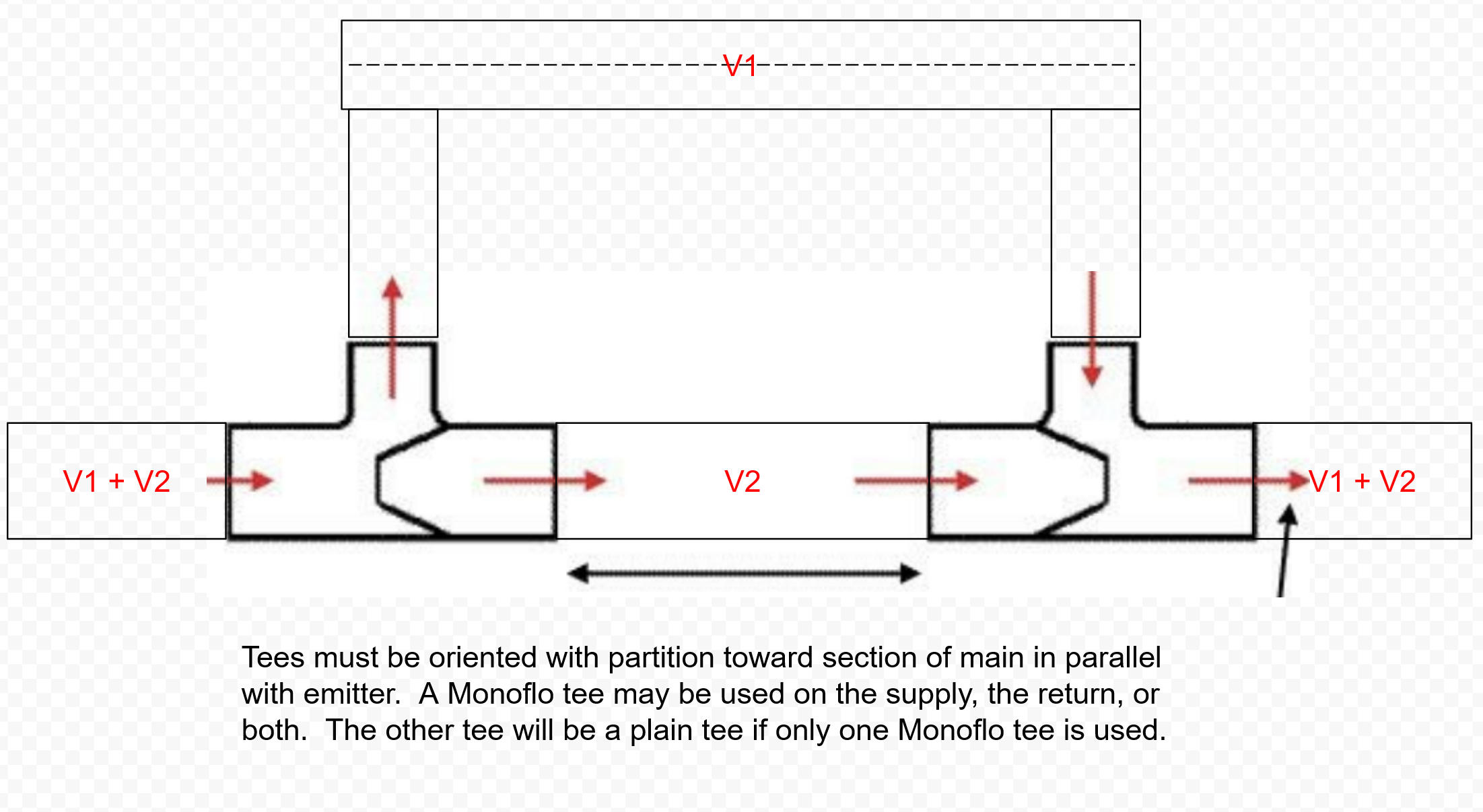
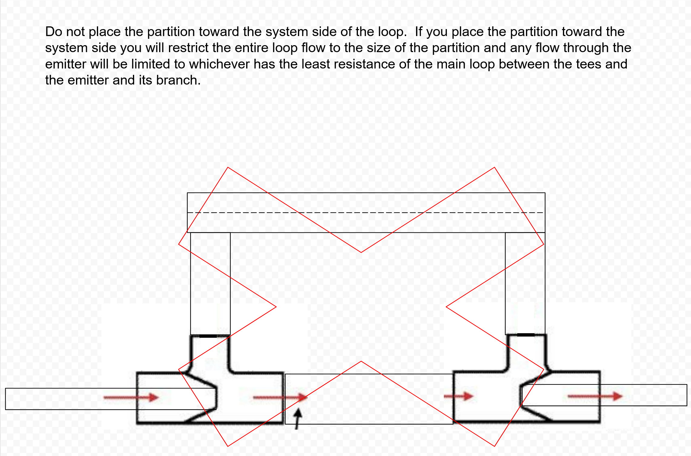
Monotflo tees must be oriented the correct way or this will happen, the flow in the main loop will be restricted to the size of the partition and any flow you get in the emitter will be the result of the relative resistance of the emitter and the main section between the tees:
 0
0 -
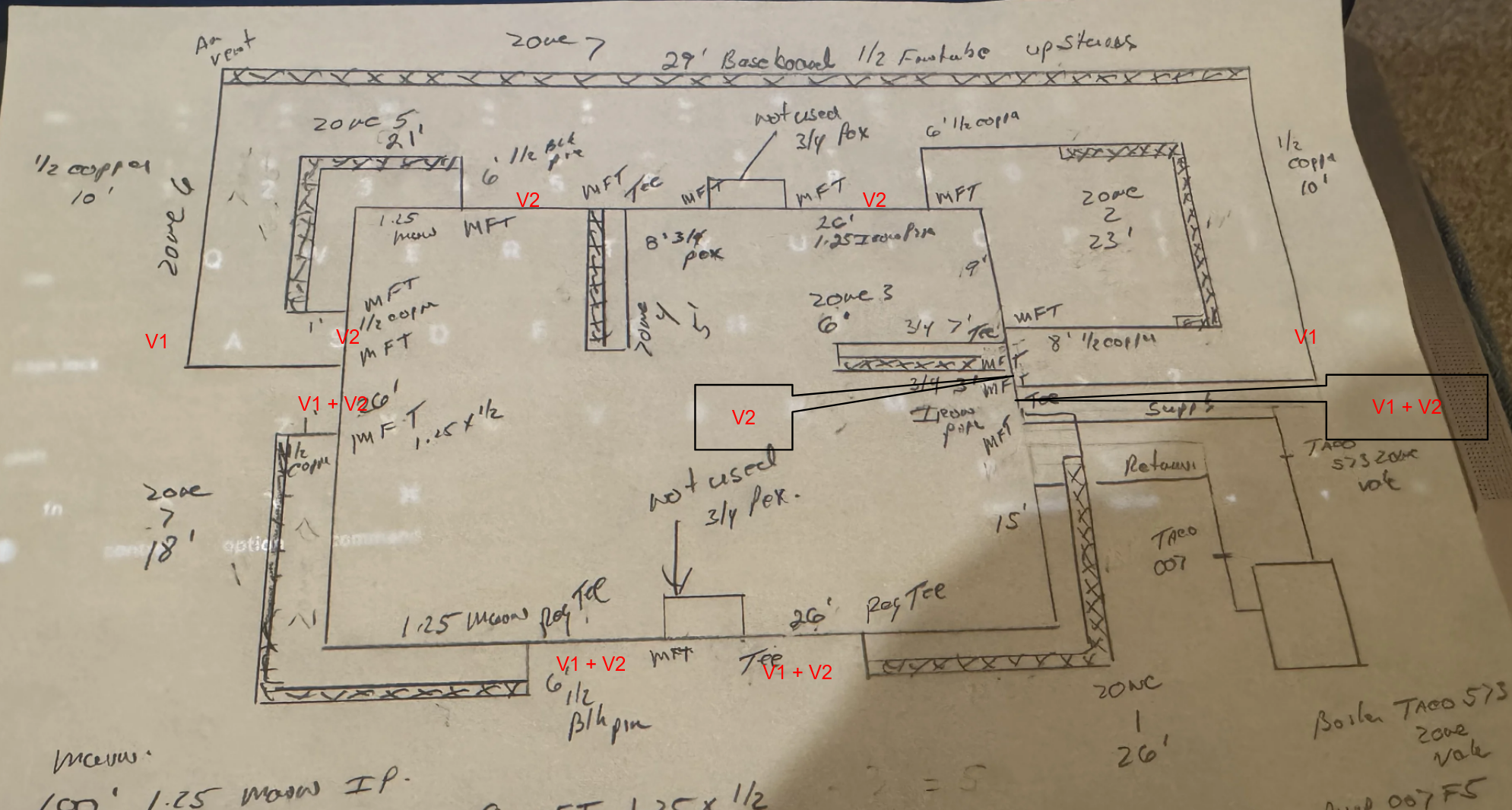
See the relative velocities added in red here. This is why you can't connect 2 monoflo tees on the same emitter to 2 different parts of the loop and you need to remove both the emitter and the monoflo tees:
It reduces the flow to all of the pairs of monoflo tees between the non-sequential tees.
0 -
The arrow on the monoflow tee should be the direction of the flow correct? The monoflow tee on zone four is on the supply side feeding zone 4. Zone 2 is the first MFT inline than the regulator tee for the upstairs and then zone 4 arrow pointing to zone 2 could that be feeding backwards towards the regulator tee on zone 4? that can't be right? I have zone two drawn wrong! Well I can see how the house was remodel thru the years.
0 -
@Skip143727 as I posted a while back the supply and return MFT are installed opposed to each other. They should have two arrows on them. Look at some tees. The arrow marked return points to the flow in the main when the tee is used on the radiation return. The arrows on the tee points to the flow in the main when the tee is used on the radiator supply.
As I mentioned before they don't make supply and return monowflow tees. They way they are installed makes them a supply or return tee..
Go with the 0012
@mattmia, You certainly can connect the monoflow tees anywhere on the loop you want. Doing so makes them work better because it adds to the pressure differential The only restriction is that they should be placed at least 18" apart, more is better and 18" away from elbows or other restrictions. With baseboard they should be place as far apart as the length of the baseboard.
0 -
look at the math on my annotations of the OPs drawing. While you can put them anywhere you want, any pairs of tees in between another pair of tees will get far less flow than if they were not between the tees. If you solved the system of equations and determined that this is what you want then you can do it. If you didn't do that, then the 2 emitters that aren't between another pair of tees will get a lot more heat than the 5 emitters that are between another pair of tees.
1 -
I agree the flow between the tees will be less than the standard main flow. In this case the upstairs zone at 1.5 gpm won't change things much. Also the upstairs zone that is "bypassing" is the zone with the worst heating problem
0 -
i think that because the main is oversized you could throw enough pump at it to make it sort of work but i don't think whoever added that 2nd floor baseboard knew what they were doing.
i'm also not so sure all of the fittings are monoflo tees, some of the pictures just look like fittings with a manufacturer's mark that kind of looks like an arrow
0 -
In the picture you can see the tee on the right is Monoflow. you can see the label with the arrows. The middle tee is a regular tee. The tee on the left is a supply monoflow you can see the label (barely) peaking out at the bottom.
 1
1 -
My house was monoflow with an 1 1/4 main built in 1955. When I bought it (1986) the old boiler had a Taco 110. The place heated fine never an issue for 34 years. At some point I replaced the bearing assembly in the circ. The second time I had an 007 and swapped it out and it worked fine. Never noticed a difference.
2020 when I sold it the new owners wanted a new boiler so I did that. Took out the gas water heater and put in an indirect with 2 zone valves. 1" Honeywells with a 4.5 Cv.
I had 95 feet of baseboard so only a 50,000 btu load which is why I put in a 1" zone valve on the 1 1/4 main and a 1" same valve for the indirect. Set up priority. The indirect was fine but the house would not heat. No other piping changes in fact I ran 1 1/4 to the new boiler and it could have been 1". In fact for a 50,000 load you could almost use 3/4". New boiler was cast iron. 8 1 1/4 x 1/2 mnoflow tees. Its only a 5 room ranch 1050 square feet.
The water would just not move around the main. Very sluggish. Boiler would go to limit and shut down. I used the original air scoop and nothing was added or changed to the supply or return piping. The water just didn't move and it was not air bound.
Finally I took out the Honeywell zone valve and replaced it with a 1" Taco with a 7 Cv. That was the fix. Thats all it took to get the water moving. Makes me wonder if the Taco pump curves are real. You can do all the calculations you want. If it doesn't work in the real world thats the way it is. The 007 should have worked in my house as well.
0 -
So the 1 inch taco zone valve is less head that the 1.25?
0 -
The Cv spec of the valve tells you how restrictive it is. Cv is the flow in gpm that causes 1 psi of drop across the valve. If you look at the specs many manufacturers' valves of 2 adjacent sizes have the same Cv.
0 -
If I remember right the 1 1/4" Taco is 7.2 Cv
The 1" is 7.0Cv
So the 1" is more restrictive . As a general rule the Cv goes up for larger valve and down for smaller valves.
Cv as @mattmia2 said is the amount of water in gallons/min that will flow through the valve with a 1psi pressure drop.
So with the above two valves a 1" will carry 7.0 gpm and the 1 1/4" will carry 7.2 gpm both with a 1 psi drop.
Then you go to a Cv Chart and look up the Cv with the flow you want to put through it.
So for instance The 1 1/4 valve will pass 7.2 gpm with a 1 psi pressure drop
If you put 10gpm through it you will have a 1.93 pressure drop
0


Categories
- All Categories
- 87.7K THE MAIN WALL
- 3.3K A-C, Heat Pumps & Refrigeration
- 59 Biomass
- 430 Carbon Monoxide Awareness
- 129 Chimneys & Flues
- 2.2K Domestic Hot Water
- 5.9K Gas Heating
- 122 Geothermal
- 170 Indoor-Air Quality
- 3.8K Oil Heating
- 79 Pipe Deterioration
- 1.1K Plumbing
- 6.6K Radiant Heating
- 396 Solar
- 16K Strictly Steam
- 3.5K Thermostats and Controls
- 56 Water Quality
- 51 Industry Classes
- 51 Job Opportunities
- 17 Recall Announcements