Trying to use an Ultrasonic GPM meter to figure out my system head.

I've been told for years my pumps are under powered so i got a fancy Keyence Ultrasonic (accurate to 2% apparently) meter to see what's going on.
Boiler is 180,000BTU net and i have a monoflo system with a single 2" supply, which splits into two zones.
18 gpm is design at 20F delta T.
Zone 1 > Two 1-1/4 split returns (70% of the BTUS, or 12.6 gpm design)
Zone 2 > One 1" return (30% of the BTUs or 5.4 gpm design)
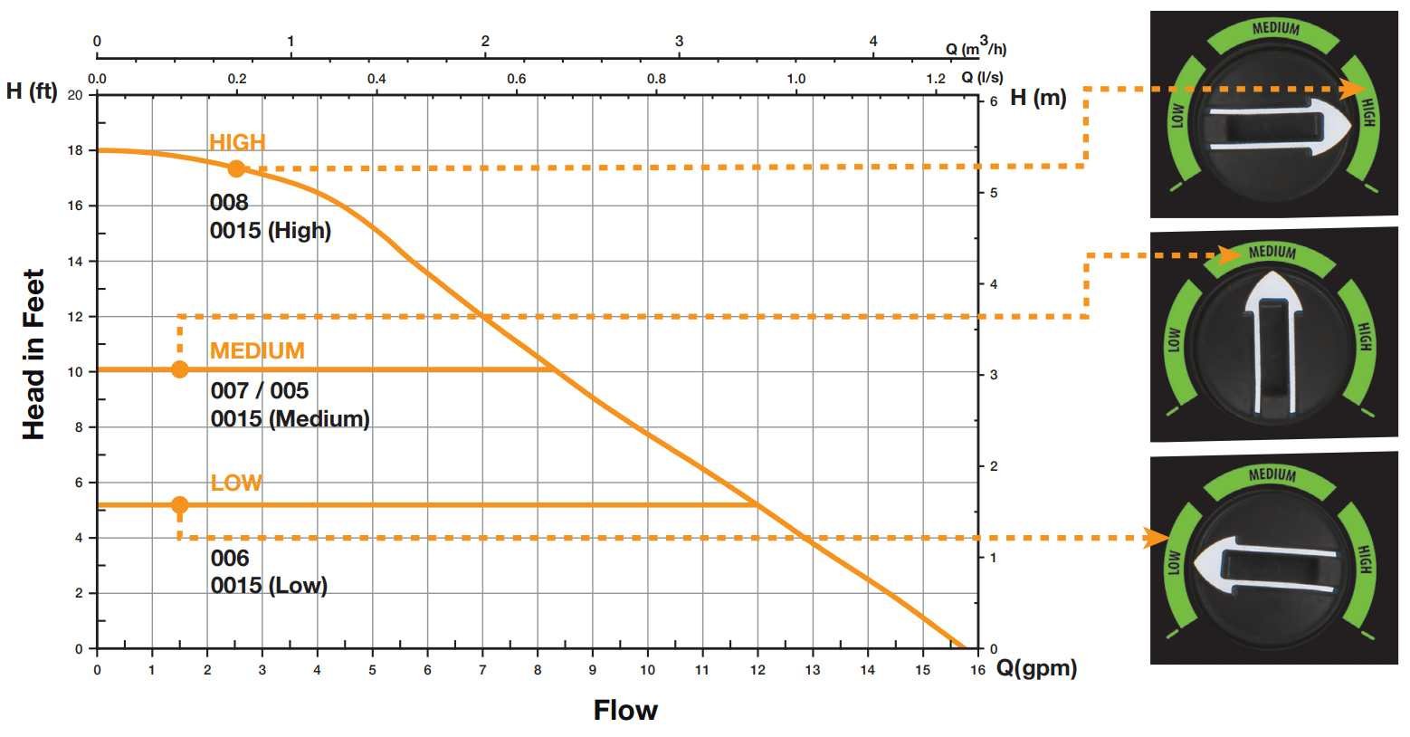
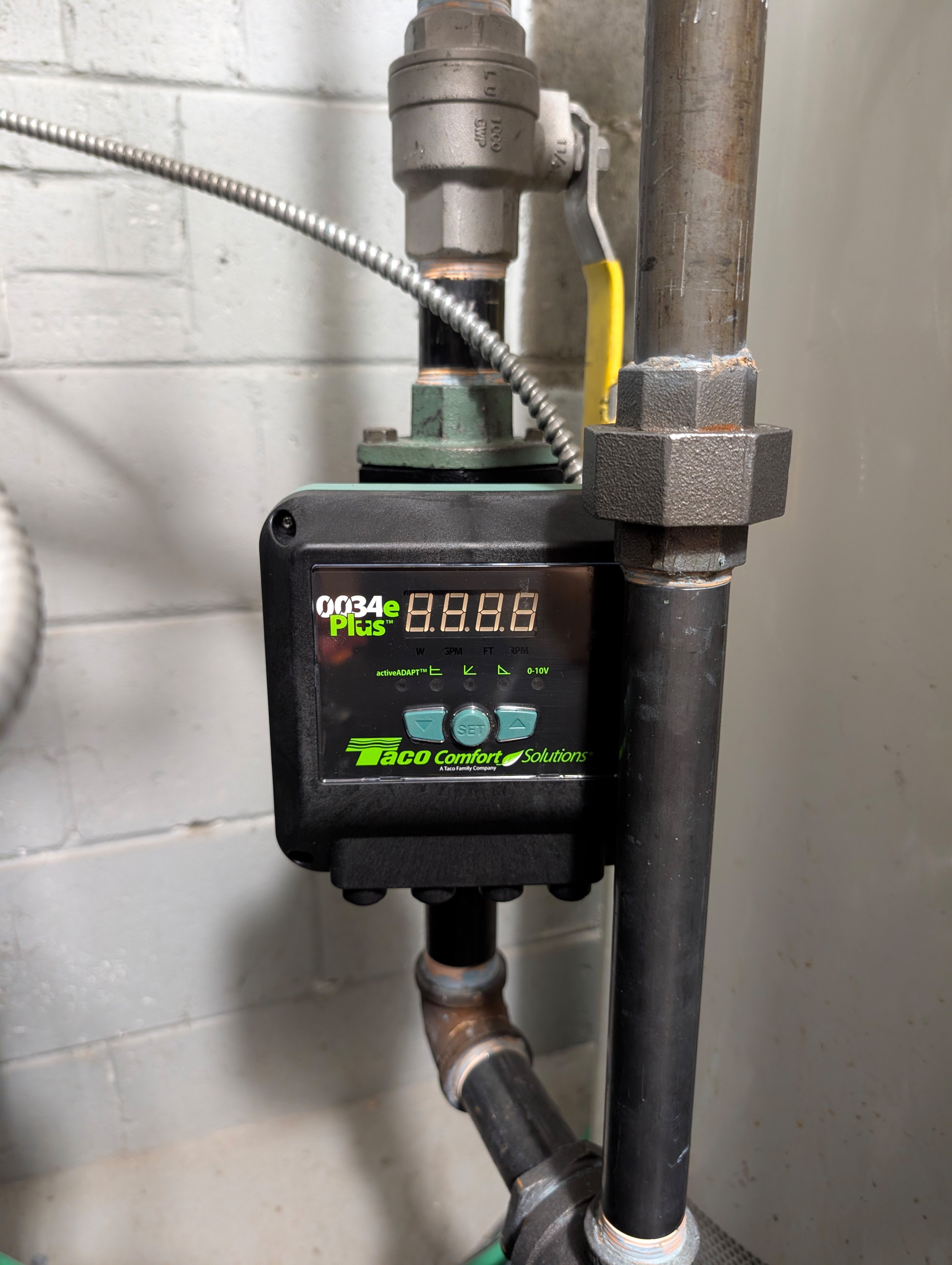
There is a Taco 0015e on each return.
At low (5 Feet of Head constant pressure)
Zone 1 - 8.35 gpm
Zone 2 - 4.4 gpm
At mid (10 Feet of Head constant pressure)
Zone 1 - 9.4 gpm (25% less than 12.6GPM design
Zone 2 - 6.3 gpm
At high
Zone 1 - 9.4 gpm same as mid
Zone 2 - 6.4 gpm almost same as mid
At high neither zone flows any faster than at medium, how can it be?
Using (Head 1 / Head 2) = (Flow 1 / Flow 2)^2 at
say 8.35 gpm at 5 feet of head, i can't arrive at 9.4 gpm and 10 feet of head,
shouldn't i be able to ?
Furthers radiators don't heat enough,
i want to replace both pumps with a single pump on the supply to
get close to design, before i balance the system. So I'm trying to figure out
which single pump to get.
Comments
-
IMHO you can throw all the ultrasonic meters in the garbage. I have not seen 1 job when they were accurate. They don't work with glycol, and they don't work with bubbles in the pipe.
If you want to get the flow you have to install a circuit setter and measure the pressure drop. Did you have both pumps running while testing or did you test 1 at a time? Guessing they were both running.
You making flow on zone 2 but not zone 1 so you need some balancing done. Put 3 circuit setters in so you can balance. . You need to balance because for some reason (piping geometry) the smaller zone is getting more flow maybe it is shorter. Can you valve off 1 zone and just run that pump? Zone 2 your are pumping almost double your design. If you can throttle that zone the other zone might pick up.
If you dont get any more flow on high speed then medium speed that tells me you out of head caacity at least on the larger zone.
On zone 1 if your flow of 6.3 gpm and head of 10' is accurate (which I doubt) to get 12.6 gpm that you want you would have a head of 40'. So something is way off.
 1
1 -
1 at a time. Combined flow was 14gpm.
Edited description, I mixed up gpms for zone 1 and zone 2
System uses water, no glycol, has a micro bubble remover, this is an industrial flow meter with mrsps over $1000, mounted per manufacturer's instructions to minimize the effect of bubbles. It's set to average the reading over 60 seconds which is advertised to have 2% accuracy, instead of instantaneous, the average reading after 2 minutes doesn't change at all. Caleffi used this meter in idonics.

 2
2 -
You are GPM limited bumping up the setpoint only increases the amount of head the pump is capable of but won't increase the flow.
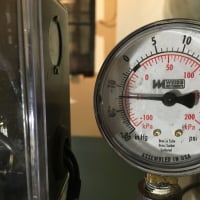
You need bigger pumps. Something like the 0026e will work.
You might be able to re-use the 0015 on the split return if you run them in parallel but might still be a bit small. Bigger pump (0026 or 0013) is the guaranteed fix with enough oomph that you can crank it if some rads are still lacking flow.
0 -
I think Ed is being a bit dramatic about the meters😉. If you do plan on throwing it away, send it my way, I'll pay freight.
In your case you are look at a difference between flows with the same meter, so if there is some error it is not causing a calculation problem.
The main issue when using ultrasonic is the cuff connection to the piping needs to be sound, pun intended.
You have the same potential for error with delta P meters on balance valve ports unless the meter is checked and recalibrated occasionally.
In a monoflo system radiators are in series. If any were added over the years the tail end will see less output.
When you measure delta T, especially on high mass radiators, you need to assure you have reached thermal equilibrium. That is the point where neither supply or return temperature is changing or moving. The radiators are then moving all the output they are receiving. This is the operating ∆T.
I think you can pump your way to a bit more output. Most electronic pumps will give you a gpm readout also, and have more adjustability.
Are you using Idronics 35 as your guide?
https://www.caleffi.com/sites/default/files/media/file/Idronics_i35_0125-compress.pdf
Bob "hot rod" Rohr
trainer for Caleffi NA
Living the hydronic dream0 -
Idronics 35 is correct, hot_rod. Got it because of it, i wouldn't trust a random cheap ultrasonic meter.
It's slightly different version of that Keyence meter. It has a "stability" indicator, mine is at full, indicating it's mounted well.
I am confident nothing was changed aside from the boiler piping and pumps, this monoflow was NEVER balanced from install 70 years ago even though it was meant to be because most of valves have an elaborate balancing mechanism, they're not regular valves. Temperature difference is a max of 2 C between the spaces closes and furthest from the boiler.
I just need to get the flow closer to design to reduce heat loss early on and have enough pressure to not mess up the monoflo if i have to throttle the early rads a lot.
Would Taco 0026e replace both return pumps if put on supply?
I'd prefer not to guess, which is why i got the flow meter.
0 -
How many BTU are you trying to move, either the heat load # or the boiler size.
It's possible the circ @Kaos mentioned could do the entire system, add a balance valve or two to fine tune.
Even if the meter is off a few % at least you have some data to work with.
Bob "hot rod" Rohr
trainer for Caleffi NA
Living the hydronic dream0 -
225000btu boiler, 180000btu net, which works out to 18gpm at 20f delta t. With the current flow the delta t is more like 25f
knowing that at 5 feet of head flow is 8.35gpm,
using
(Head 1 / Head 2) = (Flow 1 / Flow 2)^2
(5 / 10) = (8.35 / Flow 2)^2
Flow 2 = 11.81GPM @ 10 feed of head
why does it measure 9.4gpm as opposed to the calculated 11.81? a whopping 20% lower than 11.81GPM.
this is the mystery i'm trying to solve, to accurately estimate head at 12.6GPM design flow through the low flowing return to get the a pump with the closest curve.
0 -
I have 2 of those ultrasonic flow meters (1/2-3/4 & 1-1 1/4) and they work great!
Where are you getting your head loss numbers?
Set up/programming is not intuitive on them. Going thru that menu is tricky and hard to navigate. I have to have the instructions handy every time.
Are you sure you have the correct size pipe, correct type of pipe and correct flow direction? Then there are a number of other parameters that can trip you up.
Siggy just did a webinar on this-determining head, flow rate, etc.0 -
Lets step back a bit. You have two loops, with existing pumps set to max, what is the delta T across each loop? Also check the delta T on some of the rads along the loop. If delta T is high, you need more flow.
If loop delta T is OK but rad delta T is high, you might have some blockage/air or improperly selected monoflow fittings.
My guess is you have to swap out the pump on the larger loop for a bigger one at least.
0 -
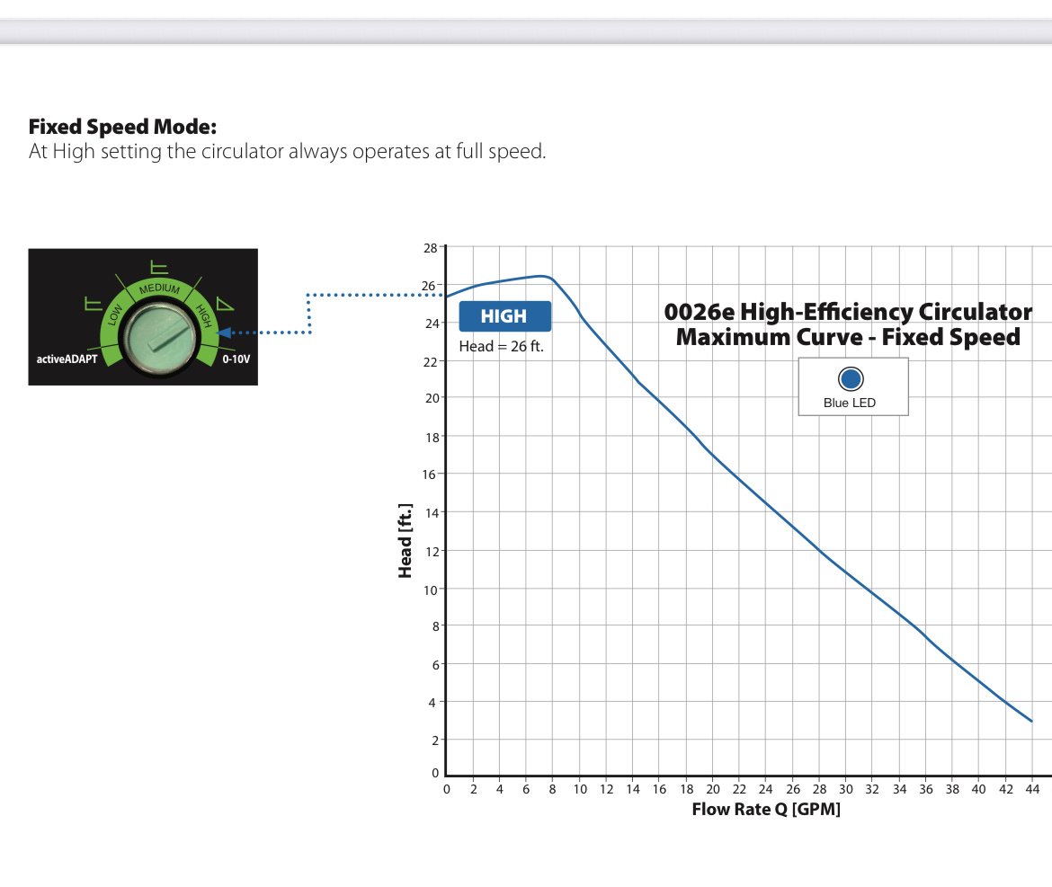
I have a Taco 0015e ECM, it's curves are in the first post. It's set to Mid, it's my understanding the head is a constant 10 at that setting, am i wrong?
The flow meter shows the GPM, it's my understanding with those two variables any
other flow/head can be calculated, but it doesn't work for the other known flow/head combination.
You're right about the menu, it was confusing at first, i have a printout next to the meter, all the things you mentioned are correct.
0 -
Instead of doing all the math just download the B& G system sizer (or use a B& G wheel) and save yourself all the trouble.
You said you messed up the zones so:
I am assuming zone 2 your getting 9.4 gpm@10' and you want 12.6 gpm on medium speed. At 12.6 gpm your head would be 17.95 (18')
Zone 1 your getting 6.3 gpm@10' and you want 5.4 gpm to get 5.4 gpm your head would be 7.94' (8')
0 -
The other part of the equation is figuring out how many btu's need to be delivered to each zone. BTU's and delta T will give you your flow rate. Measuring all the piping, components, fittings will give you the head loss. Or head loss can be charted with a regular 3 speed circulator and pressure gauges on the input & output of the circulator.
0 -
if the numbers Ed posted are reasonable, you need more pump, the 0015 isn’t going to get what you want
The 0026 not a cheap date or equivalent.
Maybe find an older style non electronic pump
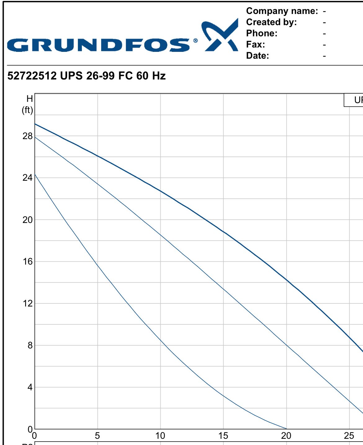
a 26-99 Grundfos would cover that load
 Bob "hot rod" Rohr
trainer for Caleffi NA
Living the hydronic dream 1
1 -
You could figure the gpm and head different ways but if the #s you got on medium speed are accurate the B & G system sizer is the way to go. More accurate than counting fittings and pipe or delta T. Its telling you based on the actual resistance of the system.
0 -
Maybe go with Alpha2 26-99F
0 -
I don't see how. Show me :) System Syzer is still going to ask you for Pipe Length (T.E.L.) I still think you need to do the math to figure out the circuits resistance, at different flow rates. I'm not really trusting the circulator readout, which in testing by Siggy has turned out to not to always be accurate.
0 -
I based what I did on the #s provided. Weather they are accurate or not I don't know but they claim that the ultrasonic is accurate.
If you go on the B & G system sizer (or use the B & G wheel) you plug in the known gpm and known feet of head. Then plug in the gpm you're looking for and it tells you the new head. You don't need to know pipe footage or fittings or anything.
You already have the piping resistance (head) at a certain flow. You plug in the new GPM you want and it does the calculation.
0 -
So I ordered a Taco 0034eplus. Will report once i install it.
I want to convert to "pumping away", which will entail adding zone valves which are restrictive, and I also needed a thermal bypass like the ESBE VTC511. I don't think the Taco 0026e would handle it. Certainly not if i used the typical 10CV zone valves.
Also looks like the plus version of 0034e has a plethora of curves and a lcd readout, hopefully i can figure out my system curve once and for all using it, and the previous readings from 0015e
0 -
I installed the beast. Flow rates at various settings i tried:
100% - 20.1gpm (27GPM shown pump)
50% - 10.7gpm (14.5GPM)
60% - 11.8gpm (16.5GPM)
65% - 13gpm (17.5GPM)
63% - 12.5gmp (16.5GPM)
C1 (constant pressure of 6ft) - 11.4gpm (15.5GPM)
C2 (constant pressure of 12ft) 16.8gpm
0015e did 9.4gpm at Medium (constant pressure of 10ft) and 9.4gpm at High (fixed speed, max curve).
If i look at the High curve, at 9.4gpm the head is 8.4feet or so.
If i solve for head at 10.7GPM which is 11ft according to the manual (50% settings using the new pump)
H2=H1×(Q1Q2)2
H2=8.4 ft×(9.4 GPM10.7 GPM)2
H2≈10.88 feet which is pressure close to 11ft.
Conclusion: I don't understand constant pressure setting and it shouldn't be used to extrapolate head/gpm.
To pump at 12.6gpm my system needs 15.09 feet of head using the formula above and at this setting the pump consumes 39W. Taco 0015e consumes a maximum of 44wats and couldn't pump more than 9.4gpm with my system.
 0
0 -
Two more or less random comments. On is minor — the formula you are using is approximately correct. The actual exponent is 1.83, not 2.
Thee other is that the power consumption of two different pumps is only rather poorly related to a given combination of head added and flow — it also depends, a lot, on the detail geometry of the both the impeller and the volute, and different pumps can be surprisingly different — even with the same layout dimensions. Further, if one or both of the two is electronically commutated, pretty much all bets are off. The exact details of pulse width, amplitude, and frequency can be very different — resulting in different power deamnds.
Br. Jamie, osb
Building superintendent/caretaker, 7200 sq. ft. historic house museum with dependencies in New England0 -
Interesting. As big of a deal energy consumption is these days, I figured it would be very similar between different ecm pumps dealing with a similar load.
The energy consumption readout can probably be trusted, however the GPM and head displayed on the pump were way off (much higher gpm, much lower head) compared to the ultrasonic.
0 -
as far as zone valves, the cv number is gallons per minute with a 1 psi drop
So a typical 7 or 8 cv 3/4 valve would flow plenty for a typical 4 gpm flow in 3/4 copper
Delta P mode is used with zone valves or TRVs Pump speed/ flow modulates with valves opening and closing
Bob "hot rod" Rohr
trainer for Caleffi NA
Living the hydronic dream0 -
The important bit, are you now getting even heat on all your rads?
0 -
Literally just installed it, this system is slow but there doesn't seem to be a difference.
I need to throttle / balance, I wanted to get the GPM right first.
0 -
I have measured an 80% error in flow readings from various ECM circs. I would not bet the farm on the displayed flow rate.
Bob "hot rod" Rohr
trainer for Caleffi NA
Living the hydronic dream0 -
We installed some Armstrong pumps and some Patterson pumps on commercial jobs. New technology, well not new anymore but 10-15 years old but the pumps come set up and programmed to run on VFDs with no controller, no sensor. "Sensorless VFDs" They sense motor amps and calculate gpm and head off of that.
As far as I am concerned it isn't 100% accurate.
0


Categories
- All Categories
- 87.7K THE MAIN WALL
- 3.3K A-C, Heat Pumps & Refrigeration
- 59 Biomass
- 430 Carbon Monoxide Awareness
- 129 Chimneys & Flues
- 2.2K Domestic Hot Water
- 5.9K Gas Heating
- 122 Geothermal
- 170 Indoor-Air Quality
- 3.8K Oil Heating
- 79 Pipe Deterioration
- 1.1K Plumbing
- 6.6K Radiant Heating
- 396 Solar
- 16K Strictly Steam
- 3.5K Thermostats and Controls
- 56 Water Quality
- 51 Industry Classes
- 51 Job Opportunities
- 17 Recall Announcements