How would you tackle these issues with my hydronic heating system? (1920s home)

Hi everyone,
What a great resource that this forum is. I have a copy of "pumping away" sitting on my desk as I write this! I was advised to ask you all for advice by a member and veteran master plumber up here in the Boston area and am unfortunately outside of his service zone, but he thought that you may be able to offer some additional feedback and advice. You all have forgotten more than I know, so I’m thankful for any help. I have also attached some pictures.
By the way, @DanHolohan I am happy to send you or anyone else here a scanned copy of the 1928 Landon radiators catalog that I purchased on EBay to help me determine the heat output.
I have two main issues:
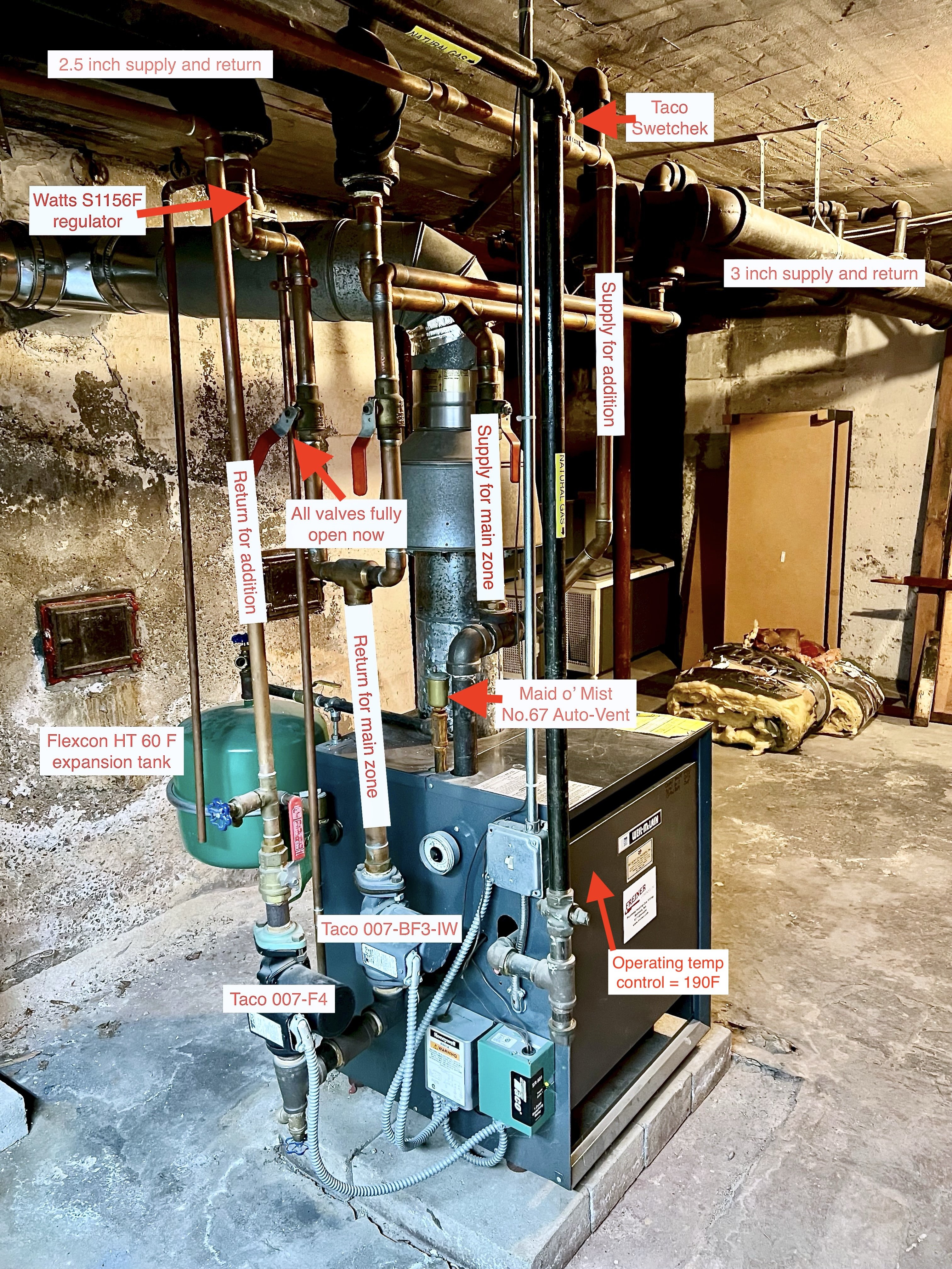
- Based on the picture of my system, I wonder if I am missing any critical components near the boiler to improve the performance issues I’ll describe below, and if you'd advise of any changes to the current setup
- I am having real issues getting the cast iron radiators hot enough to keep the home comfortable
Background information:
- The home was built in the late 1920s and seems to have originally been a gravity system. I purchased the home 4 years ago.
- I installed 1 inch fiberglass insulation on about 95% of the basement piping (the picture below was taken before I installed it) and have weathersealed the fireplace hearth and external doors. This resulted in about a 5% decrease in energy use when adjusted for average temperature, but I’m still consuming about 23 million BTU in the coldest month of the year. The attic floor was insulated 10-15 years ago with blown in cellulose but isn’t air sealed and has settled a bit.
- There are three loops: two original cast iron loops on one zone, with a longer loop (3 inch NPS that tapers down to ¾ inch) and a shorter loop (2.5 inch NPS that tapers down to 1 inch) in a direct return configuration which heats 2200sqft, and a copper loop for a 425sqft kitchen remodel/addition. A cast iron radiator was removed from the shorter cast iron loop because of the remodel and was likely about 60sqft EDR.
- The thermostat for the cast iron loops is not in direct sunlight and is on the first floor, in a room 2/3 of the way down the longer cast iron loop.
- Radiators have been bled every season and never resulted in any air being released.
Energy consumption:
- Heat load is about 60K BTU/hr at base 60F heating degree days when using historical heating bills as a reference (per Green Building Advisor’s article https://www.greenbuildingadvisor.com/article/you-dont-need-a-load-calculation)
- The heat output of the radiators is 495sqft for the longer cast iron loop, 214sqft for the shorter cast iron square loop, and 22 linear feet of baseboard plus a 4,200BTU kickspace heater for the addition/kitchen. I was hesitant to convert this to BTU without your advice on which factor to use, but using 170BTU/sqft for the radiators and 580BTU/ft for the baseboards results in a total of 138K BTU.
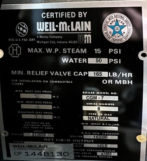
- I clocked the gas meter and am consuming about 197K BTU/hr (vs the 210K BTU input on the boiler label, a 6% difference)
- The heat load provided by a company that performed a blower door test and air leak analysis is 66K BTU. They used HERS rating software to run this number.
Temperatures:
- The aquastat is set to 190F
- I ran the cast iron loops on the boiler continuously to plot the water temperature increase. At the 45 minute mark, the return temperature only reached about 135F as measured on the pipe, the dial, and the pump. The boiler vent pipe temp was about 300F. Radiator surfaces after this test measured between 120F and 130F, and rarely achieve this temp under normal working conditions.
- In contrast, the copper loop reached 180F on the return in about 10 minutes or less.
Circulators:
- The Taco 007 for the addition draws about 0.65 amps, and the Taco 007 for the cast iron pipes draws 0.9 amps when open and 0.7 amps when the zone valve is almost closed. Honeywell technical support told me that the electrical buzzing in the switching relay for the circulator on the cast iron pipes is likely not affecting performance of the circulator itself.
Symptoms:
- Radiators, especially towards the end of the cast iron supply lines, are colder than what it seems they should be.
- I hear banging (water hammer?) on the pipes leading to some of the radiators when the system starts to warm up, especially on the first floor and exclusively on the longer cast iron loop
- When the boiler turns on, I sometimes think I hear “swishing” of water near it, but can’t pinpoint exactly where it’s coming from
- The boiler itself seems to turn on and off in a matter of minutes during the winter, or it at least seems as though it isn’t on long enough given how cold it is in the house when it does turn off
- A plumber has confirmed that one or two of the radiator valves spins continuously when opening and suggested that the valve gate may not be opening fully. Almost all radiators do not have this issue - he tested them.
If you managed to read this far, I really appreciate it, and if you’re willing to offer advice, I’d be very grateful… as would my 4 year old who complains about how cold her room gets! I can’t seem to find anyone who doesn’t want to just rip everthing out and install PEX and a high efficiency boiler. I'm a sucker for keeping this old gravity conversion system going but I'm willing to invest in improvements. I’ll be here to answer any questions that you may have.
All the best to you
Comments
-
Fellow homeowner with a gravity system here. Have you checked the radiators on the old gravity loops for balancing restriction disks in the radiator unions?
 1
1 -
None anywhere on the 14 original rads in tbe 1928 home I own. All original valve/union were replace with TRV during renovations. Really helped performance both in gravity mode and pumped.
0 -
How — if at all — are you able to balance the flows? The biggest problem with gravity conversions is balancing, and your observations lead me to believe that you have nowhere near enough flow through the older cast iron sections — and way too much flow through the newer copper section.
The boiler cycling points in somewhat the same direction: you aren't running enough water through it to absorb the power you are putting into it, so it has to turn off to keep from overheating.
The 007 on the cast iron may simply not be big enough…
Br. Jamie, osb
Building superintendent/caretaker, 7200 sq. ft. historic house museum with dependencies in New England0 -
the valves that spin are probably plug type valves where they are 1/4 turn from on to off though there are other possibilities.
the 190 setpoint probably isn't helping anything.
closing the valves most of the way on the near radiators and opening them all the way on the far radiators may help balance things though you may ultimately need a circulator with more flow at low head.
i hope the fin tube is a separate zone with a separate t-stat.
i would expect the boiler to need return water temp protection, not to cycle on high limit. are you sure the circulator for the gravity conversion is working? maybe the flo check is stuck or a valve is broken.
0 -
Could be too much flow too. Hot water used to flow nice and slow and evenly off of the mains into the risers and rads. Might be zipping down the mains right by the branches now, only letting air migrate up.
Time to do some math and maybe some well placed valves to channel flow.
I would also consider a pumping away set up and moving the circs to the supply. Might be the source of your noise/air problems…and maybe even flow. 1
1 -
is the cap loose on the vent so it is actually venting?
0 -
If the boiler is cycling on and off during cold weather, you are not moving enough water. You either have a balancing issue between the two CI loops or the 007 is not large enough.
If you were moving water through the boiler it would not cycle. As you sid the boiler is not on long enough to deliver heat.
Since you don't get air it is not an air issue.
Take the temp of both CI loops where they tie together on the supply and return and see if the water favors one loop.
Converted gravity system are finicky and converting them to a pumped system can mess with the balance.
0 -
Chiming in again. As others have mentioned, you have a balance problem. There are three distinct eras of your heating system: 1. the orginal gravity based system 2. The 1980s forced circulation single zone conversion and 3. The addition's second zone done in copper. We know the system in its current configuration is unsatisfactory, however we don't know how well the orginal conversion balanced.
The crux of your problem is the inherent incompatibility of the two zones, and insufficient isolation of the copper addition zone when there is only a call for heat from the gravity leg of the system.
The large pipes and big radiators result in a large amount of thermal mass and water which takes a long time to heat up, but once heated can be maintained by the boiler. As your data showed, to get everything up to a steady state condition takes considerably longer than 45 minutes. As things sit, during normal operation a large percentage of water cycles through the second zone when there is a call for heat in that zone. As shown in your analysis, the water in this zone heats up very quickly and returns to the boiler hot. This water contributes to the boiler temperature rising and bouncing off the safety aquastat, but doesn't contribute to the rise of temperature in the gravity loops. This results in shorter boiler cycles that have to wait for the boiler to cool before continuing.
When the is no call for heat on zone 2 the water in zone 2 reverses direction of flow and sends return water from the gravity loop back into to the supply side of the gravity loop via the zone 2 copper. Half of the heated water that would have gone to the gravity loop in the orginal single zone layout never sees the boiler.
Let the experts chime in, however, if this were my system, the first thing i would do is add a zoning valve for zone 2 which opens when zone 2 has a call for heat. A check valve before the zone 2 pump might also work, but my intuition says that the zone 2 plumbing can still divert a percentage of water when only zone 1 is running even with the check valve. This modification will, at the very least, bring you back to the system as designed in the 1980s.
0 -
Are there flo checks somewhere in each loop? are they closed?
0 -
Great question, I have not checked. I assume this would require isolating flow to the radiator and removing the valve? I ask because I wonder if I'd have to drain the system if I check each radiator.
0 -
There are two ball valves in the picture above, right on the two cast iron returns and right before the return to the boiler. I assume that they'd allow for balancing, and in fact they were in different positions when we bought the house but were moved to both fully on by a plumber thinking that it was an issue. Someone else thought I should go with a Taco 0100.
0 -
Thanks very much. What would you suggest the setpoint be changed to? Would it help reduce the frequent starts and stops of the boiler?
The fin tube is in fact a separate zone with a separate thermostat and it's separated by the Taco Swetchek shown at the top of the picture above. That's the only Flo check I have on the system.
I'm getting amperage on the circulator for the gravity conversion, though it's a bit higher amperage than the specs, and it does vary based on how much I open and close the return valve.
0 -
Great point about moving the circulator to the supply side. Based on the length and height of my longest loop, the 007 does meet the specs - which alternative circulator do you think would work if too much flow is the issue?
0 -
Good point - it is loose, though as you can see in the picture, it has rust from what appears to be a leak before we moved in. Is it worth changing out, or replacing with an alternative device?
0 -
Great idea to take the temp of the two loops individually. I'll take off the insulation and do that. If the loops aren't balanced, which loop's ball valve do I restrict? The one with the higher temp, or lower?
0 -
Run the boiler and adjust the two valves on the return so you get the same temp on each return. I see no flow checks on the CI system the copper system has one.
I think what I would do is split the CI system and put a circulator on each loop with an additional thermostat.
Not much expense. circulator, relay, thermostat a little wiring and a little piping. Both zones exist right at the boiler to its an easy job. A day's work for someone that knows what he is doing.
You will get more flow on each zone with two circulators.
0 -
Throttle the loop with the higher temp. It will take a while for it to balance out. Probably where it was set in the picture as someone did this at one time
0 -
This is so insightful, thank you. You really helped to picture the issues that can arise as the system is modified. Do you think that the Taco Swetchek at the top of the picture of the boiler isn't enough to isolate it from the cast iron zone? When I ran the cast iron zone for 45 minutes, I didn't notice a significant increase in temp on the copper pump.
And to your point, it's the balancing of those two ball valves on the cast iron return that make me nervous, I don't know where to begin and haven't had a plumber come in who can figure it out either. Maybe it's trial and error.
0 -
The only one I have is a Taco Swetchek on the copper zone supply line, as shown at the top of the picture.
0 -
That's a thoughtful idea. Would I put the two thermostats for each cast iron loop next to each other on the first floor? Or did I misunderstand? I'm going to run the test you mentioned and check the temps on each loop.
0 -
Got it! Brilliant idea to use the picture as a starting point. Interestingly, the loop with the throttled valve in the picture is the one that's hotter!
0 -
Don't be concerned about adjusting the valves. Even if you close one off the pump still has a place to pump water won't hurt a thing. The only valve you need to touch is to close the one with the hotter return. Make small changes and give it time to balance. Look at the picture and adjust that valve as in the picture for the initial setting and go from there.
Whit a big system like that low temp return and damage the boiler. Sustained running below 130 deg isn't good.
You may need larger circulators and a bypass to solve this issue but start with the water temp balancing.
Post your location we may know someone who can help you get this working. You have a newish boiler and it would be better for the boiler longevity to resolve these things in the near future.
0 -
I would correct the return piping below the two ball valves. The bullhead tee is a problem as the water in the two branches oppose each other trying to enter the single pipe. And move the circulators to pump away.
0 -
I wonder, too, how you all think we should interpret the differences in heat loads that were calculated in different ways under the “energy consumption” section of my post. It’s a head scratcher for me and you all may have some insight into why there’s such a difference. The radiators seem to want 138k but the historical calls bills and the blower door test calculate about 65k. Then the gas meter is clocking about 200k. What are these clues telling us about the system and the issues I’m having?
0 -
You don't have to pull the system apart initially. Find or borrow a thermal imaging camera and you will be able to see a distinct restriction during initial warmup.
The swetchek prevents gravity circulating, and does this by forcing the water through a vertical s. When circulated, it pushes through. When no circulation is on, the thermosiphon is blocked since the warmer water remains trapped above the colder water. (Edit: there is a check valve that gets pressed open when there is a differential in pressure aka a circulator running. This valve will also prevent reverse flow in the system assume the below discussed a failed check valve)
Without a check valve or isolation valve, half of the water going through the zone one pump would turn and goes up the zone 2 pump, through all the radiators backwards and then back onto the zone 1 plumbing bypassing the boiler.
0 -
perfect, thank you. I’ll borrow a camera from our local library. Do you think that the swetchek currently installed is enough or would you recommend an additional device to isolate these zones?
0 -
If we make the assumption the system was somewhat acceptable when initially mobilized, there is a good chance the restriction plates were removed in the 1980s.
0 -
thanks, Ed. I’m in the Boston area, about 10 minutes west of the city and next to Cambridge. I’d love to work with one of you on this.
0 -
0
-
How neat, I’m glad you caught that detail. What should the bullhead tee be replaced with?
0 -
I'd use a tee similar to the one above the ball valve at the addition return where the boiler drain is connected. Obviously with a soldered branch port instead of ips.
While your system is drained consider ball valves or isolation flanges for the circulators. And we always try to avoid installing relays or other electric components low where they could suffer an accidental drowning.
0 -
I don't believe the swetchek does anything (edit: aka it is not functioning properly) to help with the back flow of zone 1 water in zone 2 when zone 2 isn't running. Too verify this, rerun your 45 minute test with the zone 2 ball valve closed. See if this allows you to come up to temperature better. While you are at it, you can see which of the two legs on the zone 1 loops need to be restricted using the thermal camera. At the end of the test, you can open the zone 2 ball valve and see if the water is going in zone 2 backwards.
0 -
Great, thanks Mike.
0 -
Great idea, I'll try to report back on what I find. If I do verify that I'm getting backflow, what should be installed and where?
0 -
First- i need to issue a correction: The swet-chek is a standard check valve and should prevent back flow of the system if functioning correctly. I apologize for misleading you and again, I repeat, I am only a home owner, not a pro who works with these components on a regular basis. That being said, i do have a masters degree in Mechanical engineering and have taken several courses on fluid mechanics, fluid dynamics and a graduate level hvac course.
Having that out of the way, there is still the possibility that the check valve failed and allows unwanted flow.
Beyond that, I'm going to crack open some of those textbooks and see if i can't get you some concise advise on your problems.
0 -
You could try @New England SteamWorks or @Charlie from wmass . Charlie is in Springfield however.
In the old day heating systems were required to be able to heat the house at 0 degree (for Boston) withe windows WIDE open.
This resulted in massive oversizing.
So your rads are oversized. That is ok (if fact a good thing) as long as it is managed properly. Your actual heat loss of. The 65K heat loss may be correct (seems a bit low to me however).
Your boiler firing 197K input isn't much of the 210K boiler rating so I wouldn't be concerned about that. Your boiler has a hot water rating (output) of 143K so if you believe the blower door test its double the size it needs to be.
Looks like someone took the rad output of 138K and sized the boiler off that so that is better than most do which is guess.
I would focus on why the heat is not getting to the rads as it should be.
Your not getting flow for some reason
The clues that tell me this is true without seeing the job is:
180-190 supply temp with a 130 return. That is a 50-60 degree TD when it should be more like 20-30 deg
The fact that the boiler cycles on temp
and the house doesn't heat well.
It looks like a pump and or balancing issue to me.
0 -
wonderful, thanks so much! I’m going to see if there’s a way to see if it has failed. The thermal camera suggestion may offer some clues.
0 -
If the sweat check has failed that zone would overheat.
0


Categories
- All Categories
- 87.7K THE MAIN WALL
- 3.3K A-C, Heat Pumps & Refrigeration
- 59 Biomass
- 430 Carbon Monoxide Awareness
- 129 Chimneys & Flues
- 2.2K Domestic Hot Water
- 5.9K Gas Heating
- 122 Geothermal
- 170 Indoor-Air Quality
- 3.8K Oil Heating
- 79 Pipe Deterioration
- 1.1K Plumbing
- 6.6K Radiant Heating
- 396 Solar
- 16K Strictly Steam
- 3.5K Thermostats and Controls
- 56 Water Quality
- 51 Industry Classes
- 51 Job Opportunities
- 17 Recall Announcements