Lochinvar WBN080 lockout

So, the boiler quit yesterday and I got a bad sensor #1 fault code, inlet/outlet sensor. one side was open. I replaced it with a new one, and I tested the other sensors. they are good.
so what was happening is the boiler would run a cycle until heat and domestic hot water were satisfied, then shut off. it would cycle if I reset it, and run one more time & shut off. THEN I replaced the bad sensor and started it. I started it, it lit off, then it hit the high limit because I forgot to open the boiler main outlet to the system. opened the valve and now it won't fire the burner. I'm getting 3 codes … "Auto Reset High Limit Fail", APS Fail (closed), and E01
It makes spark at the ignition point, I do not get 24VDC on the gas valve… there is a spike and it jumps around but is not on long enough for the meter to stabilize a reading.
is this a board failure??? maybe the 24v rectifier?
Comments
-
anything?
0 -
You cleared all the faults, let the boiler cool and now it won't ignite?
Bob "hot rod" Rohr
trainer for Caleffi NA
Living the hydronic dream0 -
Sounds like you need to reset the high limit. Read the manual and find out how.
What does the manual say about "APS Fail Closed and E01"
Leaving a valve closed and tripping limit or flow shouldn't kill the board. You could have a 1 time fusable limit somewhere.
0 -
Sometimes, unplugging or switching off the power for 10-15 min and returning the power helps.
0 -
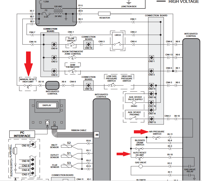
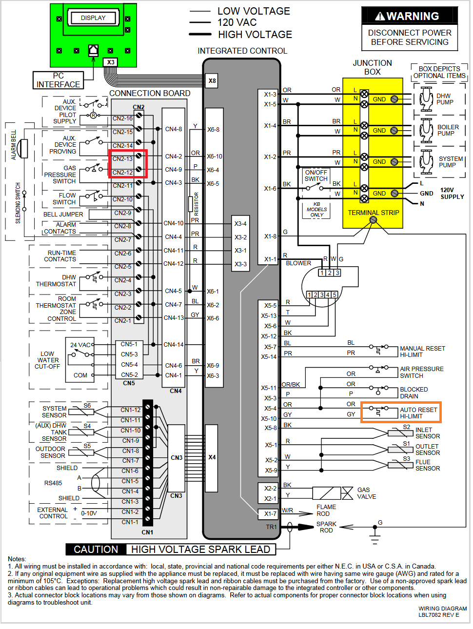
Since the Auto Reset High Limit sensor and the APS (Air Pressure Switch) sensor circuit is fed 24 VAC power through the Manual Reset High Limit sensor / switch I would check that.
It appears the control board expects to see 24 VAC at X5-4 and X5-10, I suspect the 24VAC is missing there due to the Manual Reset High Limit sensor / switch is open or tripped. May explain the E01 error too.
Appears the Manual Reset High Limit sensor / switch may be an option kit, if it does not exist with your unit I would check for 24 VAC at CN2-13 and/or X5-4, and X5-10 to start.
 National - U.S. Gas Boiler 45+ Years Old
Steam 300 SQ. FT. - EDR 347
One Pipe System0 -
I did the installation myself 10 years ago, all new stuff from Lochinvar, there is no optional temp switch installed.
I cleared codes and reset all the limits in service mode just so they would be different.
I back probed the APS and there was no 24v there during the start cycle. APS Fail (closed) is new and only appeared on my last attempt to start. it is probably due to me jumpering the APS switch, putting it out of sequence. nothing in my manual about that fault but other sources suggest it is a short. I don't believe it is a factor.
the E01 code is the only one that has been constant through this—— a bad board. I pulled the board and cleaned it, inspected etc… it looked pretty good. I tested the power caps for value and ESR as best as I could without removing them, then I went after the 24v rectifier. it was giving me a funny reading I think comes from another component in parallel so I lifted one leg of the chip off the board and,,, I broke the trace. I think I can fix it but have a new board on the way.
0 -
Looking at the circuit there should be 24 VAC at least on one side of the APS all the time unless some other upstream optional limit is tripped or defective or a loose or defective connection. I would think the APS is Normally Open (electrically) and closes when the blower creates enough pressure. So if you just jumpered it the control board may detect the out of sequence failure as you noted.
I have not found any mention of a E01 code in any of the the manuals I looked at. So maybe a bad board, but having it fail just then seems odd to me.
With ESR, a good tester will give good results in circuit, for me anything over an 1 Ohm gets more focus. Test all the aluminum electrolytics.
As far as the 24v rectifier amusing it is a (4 Diode Bridge) I would have just measures the 24 VAC input (if any) and the DC voltage out, also with the power off use the Multimeter Diode Check with the gas valve disconnected. However if there is no 24 VAC at the APS I would not expect any 24 VAC at the AC side of the 24v rectifier.
I be surprised if the new board repairs the errors, but maybe. It will fix the damaged rectifier connection.
If it was me, I'd repair the board and find where the 24 VAC stops and why.
National - U.S. Gas Boiler 45+ Years Old
Steam 300 SQ. FT. - EDR 347
One Pipe System0 -
I'm thinking the new board will fix it. the one confirmed defect the system originally had was the inlet/outlet sensor, that was the first code (sensor 1 open). it threw that along with E01. the sensor was replaced with new, and the other sensors checked. the sensor 1 code went away but E01 never did. other codes and odd stuff came into the picture… came and went, except E01…. bad board. the fault codes etc are stored on the board, in the main control. that will all go away with a new board. next question is, who repairs these boards?
0 -
OK, I guess my question is did the E01 code preexist prior to the sensor failure. Do you know for sure E01 means a bad board ? In general changing the sensor should not have caused any other issues with the board.
If the boiler was powered down during the sensor change, one possibility that a new board would repair, is if there are on board switching power supplies for various voltages needed, with aged capacitors one of the switching supplies may not be starting correctly after the boiler's power up. Often it is the small aluminum electrolytic capacitor(s) fail due to high ESR (often greater than 5 Ohms depending on the capacitor). The small aluminum electrolytic capacitor(s) are not expensive or hard to change but some equipment and attention to detail is needed to replace them.
There are many electronic board type repair business out there. They mostly do industrial electronics where the repair is expensive from a home owners point of view. The problem is for the cost of the replacement board compared to the shop labor rate, boards like that are often not economical to repair. Especially if the repair (and troubleshooting) is more in depth than just changing a half dozen capacitors. There may be a small specialty shop that do that type of repair that I am not familiar with.
EDIT: Here is one such place I found with Google.
HVAC contractors will state the liability issue, so the HVAC contractors are just board swappers. And electronics repair isn't their thing anyway.
As near as I can tell a competent repair that restores the board to the original factory specifications without modification the liability is not really an issue but more of an excuse not to repair.
Do you have a friend that can do electronics repair if you can't ?
National - U.S. Gas Boiler 45+ Years Old
Steam 300 SQ. FT. - EDR 347
One Pipe System0 -
Did you get all the air out after changing the sensor?
0 -
I got the air out after the change. you don't lose more than about 2 cups of water in the process.
the Sensor 1 and E01 faults occurred at the same time and started the initial shut down.
Sensor 1 had an open circuit. I expected the sensor change to be the cure but E01 never went away. some of the things that happened after that are probably my fault and only muddied the waters. my electricity is better than most. I taught it 20 years in trade school and I build guitar amps from scratch
everything is on hold until new board arrives. thanks all
https://alltroubleshooting.net/lochinvar-boiler-error-code/
0 -
Both my computer browsers complained that the error code link was not safe so I did not go there.
With some more google searches; with Lochinvar products the E01 code seems all over the place.
E01 (No Ignition): This is a general ignition failure code and can usually be resolved by resetting the boiler.
E01 / E1: Low water pressure.
The Lochinvar E01 error code signifies a memory lockout
Not sure why the memory would get damaged or corrupted by a sensor change-out.
With that experience I would think patching up the broken trace would not be too difficult. Sometimes removing the component, repair the board with a small wire or component lead cutoff and reinstall the component is all that is needed. Also 30 AWG Kynar wire or the like could be used to make a short jumper.
National - U.S. Gas Boiler 45+ Years Old
Steam 300 SQ. FT. - EDR 347
One Pipe System0 -
welp…. put the new board in, cleared a cluster of faults, it still won't start and now it locks out and says "AHRL/HEX TEMP SWITCH" . what the hell? its a new sensor…. or is there a "switch" I don't see? I ohmed the new sensors before installation, I've checked resistance with them installed (readings changed due to cold inlet water) readings seem reasonable, the chart doesn't list values for water that cold. I also measured from the connector on the PC board side to verify wire connections at the sensors.
it will fire the ignition but apparently the gas valve is not opening. btw, I pulled the valve and powered it up with a variable supply and it opened. I could blow through it but not much, I assume that is due to a jet. I thought of replacing the valve but why would I be getting this hex temp switch thing?
and PS… there was a bad cap on the old PC board. I plan to repair it for a backup
0 -
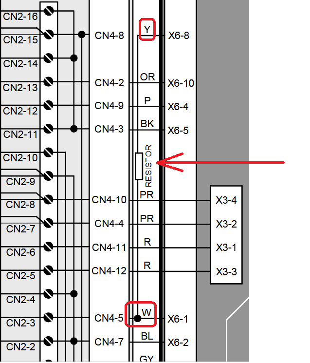
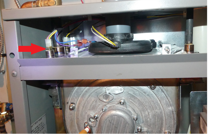
one more thing… there is a rectangular thing that looks like a ceramic dropping resistor on the water jacket. its high on the right hand side and about middle of the heat exchanger/jacket. it is not in any of the parts books. it has 2 white wires on one side, and 1 yellow wire on the other, it measures about 225 ohms
0 -
I suspect it is a power resistor. Its values may be printed on one side. Also it is shown near the top of the partial schematic posted above.
 National - U.S. Gas Boiler 45+ Years Old
Steam 300 SQ. FT. - EDR 347
One Pipe System0 -
Is there a board setting that defines the model of the boiler ?
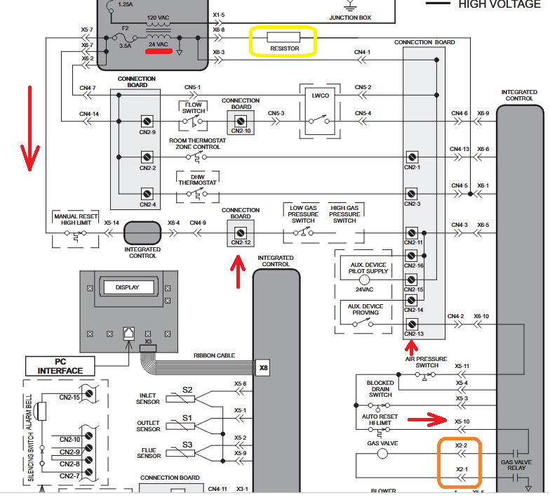
If it appears to want to fire but if the gas valve never is powered I would chase the 24 VAC though all its connections as far as it goes, many places it should be found. Once it is rectified I suspect exiting the board at X2-1 and X2-2 it may be DC (full wave pulsating DC) in which case using the chassis ground may give odd measurements. I would measure the DC at (across) X2-1 and X2-2 .
Where the 24 VAC stops may be a clue.
 National - U.S. Gas Boiler 45+ Years Old
Steam 300 SQ. FT. - EDR 347
One Pipe System0 -
To me the ARHL (Auto Reset Hi-Limit) is directly in the path of the power to the gas valve, I would look for poor connections loose or oxidized crimps, bad solder joints, etc. Carefully probing with a multimeter during an ignition attempt and close inspection of the related connections also Pin fitment etc. may reveal a connection that it not as secure as it should be.
The connection may only fail under the load of the Gas Valve. An Ohmmeter is not much of a load.
Sadly these days "New" anything does not mean 100% functional, be suspicious of everything. Assuming "New" is good and 100% operational can and does waste a lot of time.
National - U.S. Gas Boiler 45+ Years Old
Steam 300 SQ. FT. - EDR 347
One Pipe System0 -
If I had to guess from here the control board is seeing an excessive voltage drop across X5-4 and X5-10 or maybe just no power from upstream. Which is why it keeps flagging the ARHL (Auto Reset Hi-Limit).
I'd closely inspect the Connection Board also, terminals and solder joints.
National - U.S. Gas Boiler 45+ Years Old
Steam 300 SQ. FT. - EDR 347
One Pipe System0 -
The ceramic resistor looks like a 'Pull Down' resistor for the DHW Thermostat input, not sure why it would be needed on the DHW input only OR it adds a few watts of added heat to what it is mounted to during a DHW call for heat, maybe some kind of hysteresis.
National - U.S. Gas Boiler 45+ Years Old
Steam 300 SQ. FT. - EDR 347
One Pipe System0 -
pretty convinced the resistor is just a voltage dropper, and not a factor.
been over all the terminals and connections
power to the valves, etc during start cycle is on for so short a time my digital meters can not stabilize for a reading. I got Fluke and Triplett and others but don't have an analog meter anymore. I will get one.. think I left one with my brother
the gas valve has its own rectifier. power is AC up to the valve
which terminals on the board are 12 and 13? how is it numbered?
and…. WHERE IS THE .. Auto Reset Hi-Limit Sw????
0 -
You mentioned the resistor, so I commented about it. It appears when the DHW thermostat is closed there is 24 VAC across the resistor. When the DHW thermostat is open the 24 VAC is removed from across the resistor, so not sure the intent of the resistor without reverse engineering the board. Yes, I believe it has nothing to do with the current issue.
An analog meter will work, also 24 volts worth of incandescent lamps will work too, like two old school automotive marker lamps (or two 12 V test lights) wired in series. The test incandescent lamp current should be in the same ballpark as the Gas Valve current.
I have seen some boards where the a Gas Valve full wave bridge rectifier is on the board just before the circuit leaves the control board towards the Gas Valve. Apparently I erroneously assumed that was the area that you damaged.
" then I went after the 24v rectifier. it was giving me a funny reading I think comes from another component in parallel so I lifted one leg of the chip off the board and,,, I broke the trace. "
Quite often the rectifier is in the connector at the gas valve.
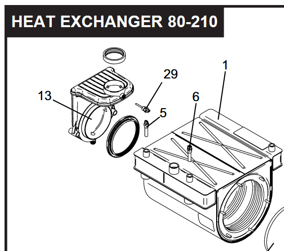
I would think item number 6 is the ARHL (Auto Reset Hi-Limit). I think there was another thread where a similar boiler had an intermittent dual sensor in that area, it had 4 wires going to it IIRC. Maybe I can find that thread. Found it. That thread reads a lot like yours. I think the fix was to replace the sensor, when the sensor leads were flexed it was intermittent. The other thread is three pages long.

CN2-12 and CN2-13 Red box below, ARHL (Auto Reset Hi-Limit) Orange Box below. You could chase out the Orange and Gray wires from X5-4 and X5-10 to the ARHL (Auto Reset Hi-Limit). Keep in mind this diagram is Rev. E your unit may be slightly different.
 National - U.S. Gas Boiler 45+ Years Old
Steam 300 SQ. FT. - EDR 347
One Pipe System0 -
Did you have an add on low water cutoff installed? Not the electronic one that is plug and play. Something like a Mcdonnell Miller that they have to wire up after the fact. If you do I would suspect that they have that installed in the limit string with the high limit and flue temp probe. It won't show because it's not tied into the board but the safety circuit will be in series with the limit circuit. It could be any add-on device that's wired in that limit string.
0 -
there are no ad on safety switches.
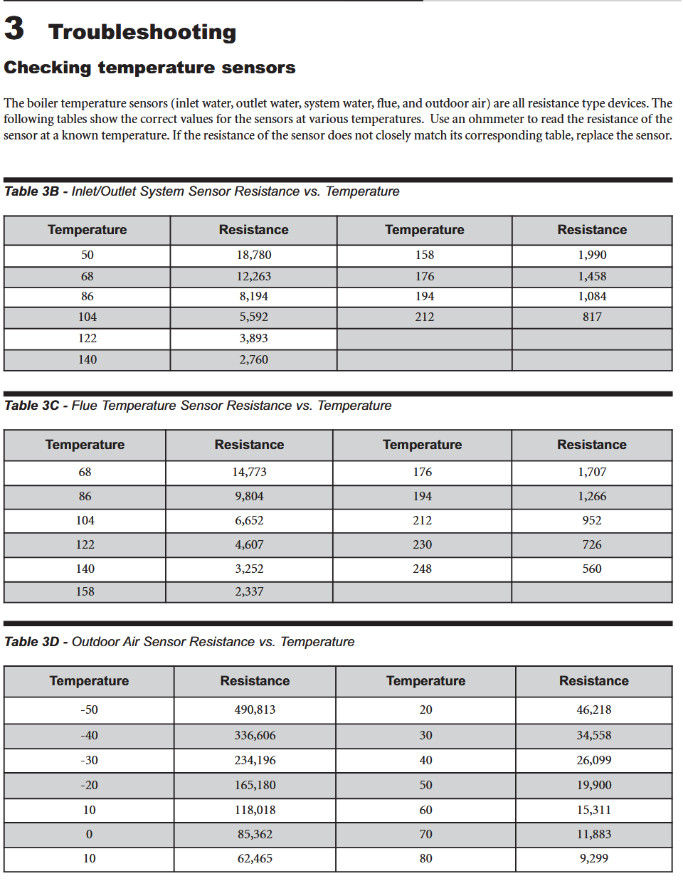
the sensor is new, the old one was defective. that was the original problem…. "Sensor 1 open". the new sensor ohm readings seem to be OK, I guess. I have tested all 4 wires from the panel side and read same as direct to the sensor. today Y/R reads 24.9k and O/Gray reads 12.5k. room temp is 68 or so. the water manifold is cooler. the readings are high but it should be low readings that set off the fault. so how high is too high? and does it matter???? when I took the new sensor out of the box it measured 16k and 8k at about 70F. the r/y side should have been 12k. there are no numbers in the chart for temps less than 158F for the high lim (o/g) side. is it possible the sensor is bad???? where do i get SOLID numbers to test with? its making me crazy.
it will not enter "service mode" either. I guess that makes sense
I'm getting a new valve today anyway just because. I assume the old one is good as a spare. I plan to put my O-scope on the valve and see it cycle
0 -
I believe the dual sensor is (1/2) sensor is a thermistor (S1 on the diagram), so variable high resistance that changes with temperature, usually NTC (Negative Temperature coefficient), temp goes up the resistance goes down. The other (1/2) sensor is a (needs to be) thermal snap switch type (Auto Reset Hi-Limit, Orange / Gray wires) which when closed at room and normal boiler operating temperatures has a very low resistance, like less than 1 Ohm to support the load current of the Gas valve. At least that is what the wiring diagrams are telling me. You should have the original documentation, are they significantly different than my postings ?
You may have the wrong sensor. Or your new sensor is defective. If you prefer chase out the 24 VAC that powers the Gas Valve and see where it stops.
Additionally the flame proving time should be long enough for a digital meter to settle if normal voltage is actually present. So an analog meter or and indicating load (such as lamp(s) that I like) should not be needed in this case.
If you replace the Gas Valve you probably need to do a combustion analysis. A combustion analysis may not be a bad idea for a tuneup when you get it running.
National - U.S. Gas Boiler 45+ Years Old
Steam 300 SQ. FT. - EDR 347
One Pipe System1 -
Here is a resistance chart from the manual of the other model in the other thread I posted. Keep in mind this is for thermistor type sensors. Self resetting Snap type thermal switches are usually open (infinite resistance) or closed (low resistance). I believe 1/2 of the ARHL (Auto Reset Hi-Limit) is NOT a thermistor and actually is a Snap type thermal switch. Having thousands of Ohms resistance in series with the 24 VAC current path to the Gas Valve makes no sense.
 National - U.S. Gas Boiler 45+ Years Old
Steam 300 SQ. FT. - EDR 347
One Pipe System1 -
thank you 109… (and I have that chart in the manual that came with my boiler)
heres the update… everything seemed to keep coming back to the sensor so I bought another one. comparing ohm numbers with the 1st replacement shows they are different. the 2nd replacement has "zero" ohms on the orange/gray pair (auto reset), thats the same as the original. the 1st replacement switch had something like 8K (all tests done prior to installation). resistance on the outlet temp sensor was all different. the original was about double the chart numbers. I expect that was read as "open" by the control board. the first replacement was a little high, the 2nd sensor was pretty close. I made readings with sensors in cold, warm, and hot water. conclusion…. wrong part.
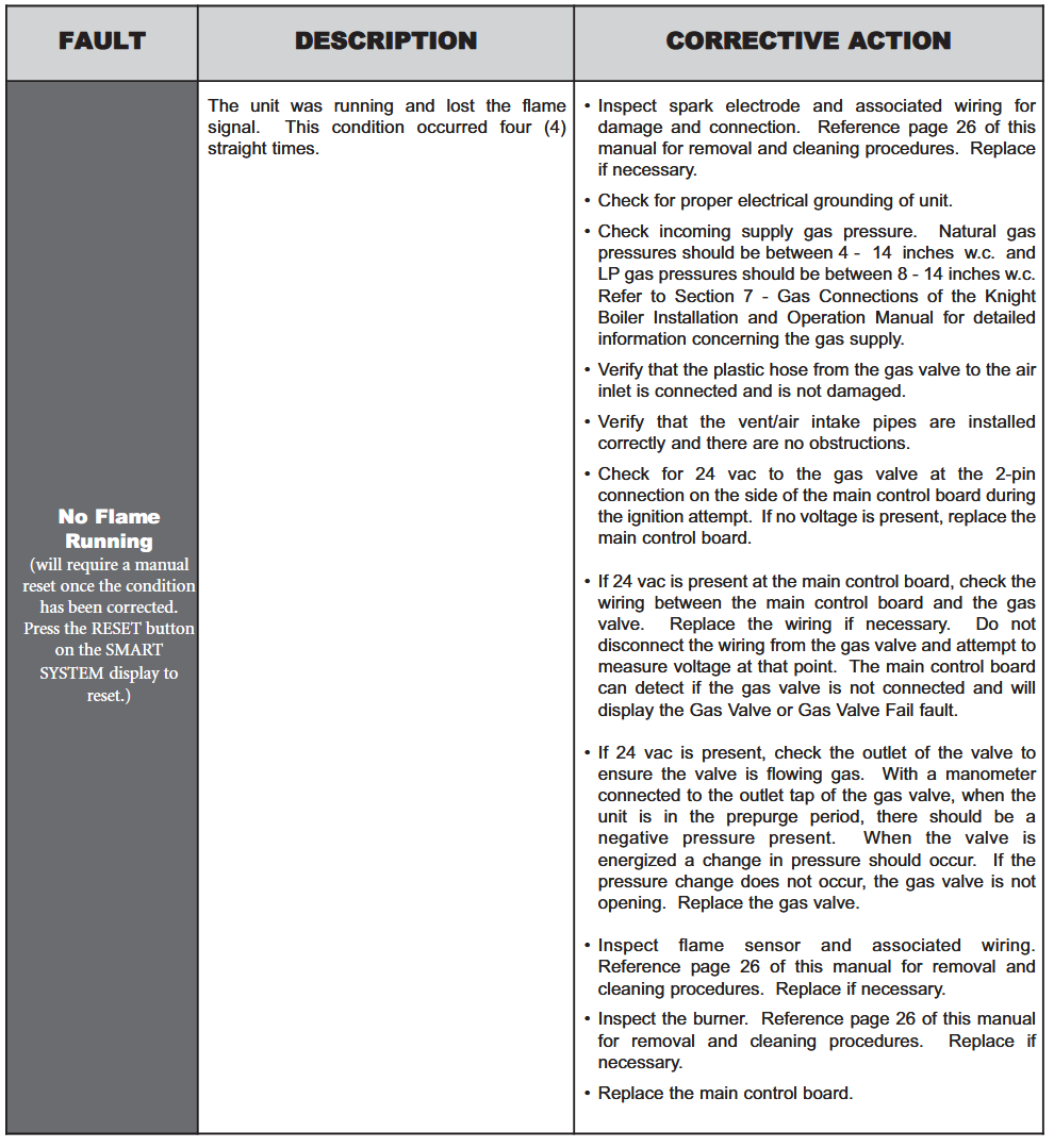
so…… I put the new sensor in and it fired right up. it ran fine, but shut back down last night. code is "NO FLAME RUNNING, E01. it reset and is back running now.
my OAT (outside air) reads high. I temporarily reset the high limit until I get other things squared up. it may require a new sensor.
I'm going to get new batteries for my gas sniffer and check the CO etc. I bought it new 3 years ago because the plastic flue warped and I had to replace it. I've used it 3 times since new. getting a tech to come out is at least a week wait even in the summer, and 250 an hour…. on the clock when driving across town too. I have a Bacharach Intech, so not a cheapo meter. the manual says the CO sensor is good for more than 3 years. oxy sensor is good for 3. should be able check for 20.95% right?
0 -
OK, I thought you said your resistance chart did not go down to room temp.
From that chart all the thermistors seem like they may be typical 10K at 25 degree C or 77 degrees F. however they may have different curves since at other common temperatures listed they have different resistances.
Well good, it seems you are in better shape and understand that dual sensor better now. When troubleshooting I am suspicious of everything, new or otherwise.
Maybe with the "NO FLAME RUNNING, E01." and the "OAT (outside air) reads high", it just a bit more TLC.
As far as test equipment calibration and boiler setup, follow the manufactures recommendations,
National - U.S. Gas Boiler 45+ Years Old
Steam 300 SQ. FT. - EDR 347
One Pipe System0 -
I reset the hi & low SH setpoint limits and the OAT points. I think I need a new outside temp sender, its off by 20* at least. reads high
the good news is the boiler ran normal all night and today (so far). the other news is I still have E01 in the data logging (C4). the fault doesn't show on the main display, only in C4. I've cleared it (through D1) but it comes back.
my sniffer needs a new oxygen sensor so I haven't done that yet.
thanks for all the help. I'll check back with any developments
0 -
another lockout…. "no flame running" "E01"…..
it made about 48 hours of normal operation. wish I knew what E01 meant
0 -
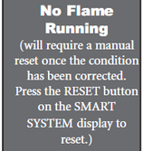
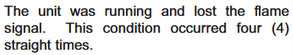
If "no flame running" & "E01" is actually two independent but related codes (possible E01 codes listed earlier in thread), the flame may have dropped out and the boiler was unable to relight.
E01 (No Ignition): This is a general ignition failure code and can usually be resolved by resetting the boiler.
I would review the Corrective Actions below. Also when the unit is running gently (strategically) wiggle the wiring harness to verify there are no intermittent connections that would cause the flame to drop out.
Also I think I saw a thread where you cleaned the combustion chamber. Maybe it needs a combustion analysis and tuneup. How is the Flame Signal and flame quality ?
 National - U.S. Gas Boiler 45+ Years Old
Steam 300 SQ. FT. - EDR 347
One Pipe System0 -
I suspect the connector on the sensor. both the connectors on the top of the boiler are fragile. the ones below on the fan, valve, and board look fine though. and my, how time flies… the boiler is15 years old. I searched for connectors… no dice, they sell the harness though. I may have alternatives
I'm going to check the flue asap
thanks again for the help
0 -
if E01 is what I found online is correct. The manuals I looked up do not reference codes just symptoms. In one are it said it was water pressure, in another was ignition. Not helpful! Below would be based on if it is in fact water pressure.
If you keep getting the E01 error, what does your water pressure gauge read. Min of 12 needed normally. It could have a plugged sensing port. When servicing we would normally remove pressure sensor and flush out tube and make sure on press switch that it had a clear inlet hole.
1 -
Pin fitment or the the pressure the female part of the connector exerts on the male pin needs to be adequate. Also poor crimps or crimps that the wire has oxidized or corroded inside of the crimp are also suspects. A vendor like Digikey.com or Mouser.com may have the connectors and pins, matching it up correctly may prove time consuming, there are many connectors and often subtle differences.
Do any of the connectors show signs of discoloration due to heating (loose connection) ? In the event of a poor connection the boiler may shut down quickly so connector body heating may not be evident.
National - U.S. Gas Boiler 45+ Years Old
Steam 300 SQ. FT. - EDR 347
One Pipe System1 -
With the WBN080 wiring documents I did not see a pressure sensor.
National - U.S. Gas Boiler 45+ Years Old
Steam 300 SQ. FT. - EDR 347
One Pipe System1 -
109A, I was wondering about that, the search I did was not coming up with a clear answer. May be a low water cutoff. Still find it odd I could not find error code chart in IOM manual, service manual or user manual for that boiler. All the Lochinvar boilers we installed over the last 20 yrs usually had an error code chart in one of the manuals.
0 -
I would call Lochinvar tech support tomorrow morning and ask them what the E01 code is for sure as It is not in manual. Odd.
1 -
The service manual has these types of charts but no mention of E01.
https://s3.amazonaws.com/s3.supplyhouse.com/manuals/1249544894162/Lochinvar-KnightBoiler-ServiceManual.pdf
 National - U.S. Gas Boiler 45+ Years Old
Steam 300 SQ. FT. - EDR 347
One Pipe System0 -
ha ha… I talked to a Lochinvar rep about a week ago. we seemed to agree that E01 is a pretty generic code. I think its the end result after every other code has failed. and I did see several references that indicated a bad board (posted a link way back). anyway, I got a new replacement sensor and tested all 3 at different temps. the results made me suspicious of the 1st replacement so I called the parts warehouse with questions. they didn't know anything but they gave me the number for the rep. he is a great guy and we talked for maybe 40 minutes about what happened and what was done. he went through his books and eventually confirmed the 1st replacement sensor was not the correct part, and the second was.
0 -
the lockouts continue. once a day, sometimes more. I paid a tech to come out and he found nothing wrong. 450 down the drain because I knew more about the system than he did. plus, he didn't bring a gas analyzer. the oxy sensor for my Bacharach sniffer arrived right after he left so I tested it. hi and low combustion are in the range but not optimal. I might fool with it more this afternoon.
I still get "no flame running" and "E01". the "no flame" will clear but E01 stays, but is says "no fault stored"
I have disconnected the outdoor temp sender in order to uncomplicate things a bit
is there a way to completely reset the brain box???? go back to all factory settings
this is commencing to annoy me
heres the numbers. low fire was at 20%, thats as low as it modulates. CO is ppm
- LOW FIRE….. (02)=9.2% (CO) = 18 (CO2)= 6.7% (EFF)= 89.2%
- HIGH FIRE (O2)= 5.2% (CO)= 44 (CO2)= 8.9% (EFF)= 88.8%
0 -
Intermittent problems are typically the worst to find. Although this issue seems consistently intermittent.
So, to me, the question is what is causing the flame to go out OR why does the control board think the flame has gone out ? Is the Flame Signal consistently good ? Catching it in the act, if possible may reveal some data. Can a normal run cycle(s) be delayed so you can watch it closer while it is running ?
I would think there is a way for a complete factory default reset, if so I have not found it, maybe the PC software is needed, maybe only the Software Engineer knows.
Possibly the E01 may only go away after a certain number of boiler cycles with no issues, again maybe only the Software Engineer knows.
Is the 120 VAC to the boiler stable ?
Is the 24 VAC stable ?
Does your unit have the On-Off switch on the Gas Valve connector ? I think I may have read that it was eliminated due to intermittent issues, not sure.
Is all grounding and internal ground bonding intact ?
National - U.S. Gas Boiler 45+ Years Old
Steam 300 SQ. FT. - EDR 347
One Pipe System0


Categories
- All Categories
- 87.7K THE MAIN WALL
- 3.3K A-C, Heat Pumps & Refrigeration
- 59 Biomass
- 430 Carbon Monoxide Awareness
- 129 Chimneys & Flues
- 2.2K Domestic Hot Water
- 5.9K Gas Heating
- 122 Geothermal
- 170 Indoor-Air Quality
- 3.8K Oil Heating
- 79 Pipe Deterioration
- 1.1K Plumbing
- 6.6K Radiant Heating
- 396 Solar
- 16K Strictly Steam
- 3.5K Thermostats and Controls
- 56 Water Quality
- 51 Industry Classes
- 51 Job Opportunities
- 17 Recall Announcements