Electrical

I am trying to create a wiring diagram, it's for learning purposes and, I don't even understand where to start: I have been struggling for weeks I don't understand how would you only draw out the low voltage side.
ou have 2 oil boilers that are running for steam heat and domestic hot water.
Each boiler had an aquastat set at 150*F to make hot water. This will keep both boilers ready to make hot water as soon as there is a call.
When thermostat calls for heat, both boilers need to start. Pressurtrols will control steam pressure.Customer wants a Summer/Winter switch to prevent overheating in the shoulder seasons.
Your assignment is to wire the low voltage side of the controls so that boilers maintain temperature and can call both boilers on when thermostat calls for heat.
One last piece of information,
Heating circuit can not come from only one burner. It had to be it’s on circuit, so that either burner can be shut down with out affecting heat
( I am trying to learn how to design wiring diagrams and, its been very difficult. )
Comments
-
what does this summer/winter switch do? if there is a call for heat both boilers fire on the vaporstat. if there is no heat call both boilers need to run warm start on the aquastat for dhw. that doesn't change with the season.
0 -
Just start with the source of the low voltage. It needs to be independent of the boilers, so not connected to them at all—yet.
Do it one step at a time, the only part that's going to be more than simple is staging the boilers, that can get complicated.
PS: Better to say up front if it's an assignment, less chance of someone accidentally doing the work for you after you paid good money for the schooling.
 1
1 -
It's not school or anything I work full time, a coworker created this for me and is having me draw it out but, I am completely lost.
0 -
May be some useful explanations and drawings here.
Bob "hot rod" Rohr
trainer for Caleffi NA
Living the hydronic dream0 -
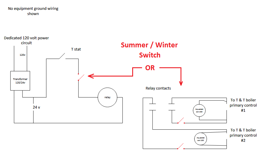
Something like this?
1 -
Ok, good. It said "assignment" above, so I wanted to be sure.
A lot of the controls will depend on how the boilers are actually piped. I'm going to assume that they're piped in parallel, so that either one or both can make hot water and heating steam and the summer/winter switch will merely inhibit one boiler from making steam. I'm also going to assume that the hot water production is independent of the steam production and is separately controlled.
After that, you need to start with 24 VAC, so a transformer somewhere, fed from a circuit that won't be switched off. The hot from that will go through the thermostat contact (in on R, out on W, C from the transformer if needed). Use the W call from the stat to throw two relays, one for each boiler. The summer/winter switch can interrupt the power to one of the relays to disable the steam production. On each boiler, use the relay normally open contact to bypass the aquastat (use C & NO, one to one side of the aquastat contacts, one to the other), so that when the relay closes power can go around the aquastat to fire the boiler even though the aquastat may be satisfied. The pressuretrol (or rather, should be a vaporstat for better control) should be inline with the aquastat (one for each boiler). Coordinated pressure settings will allow the boilers to stage in & out so that if one boiler can carry the load the other will shut down.
1 -
Using @EBEBRATT-Ed 's example just add the appropriate switch for the desired Summer / Winter functionality.
As far as to learning to draw / create wiring diagrams, study them, as many as you can until you understand what they and their symbols represent.
 National - U.S. Gas Boiler 45+ Years Old
Steam 300 SQ. FT. - EDR 347
One Pipe System1 -
I don't get the need for a summer/winter switch.
What is is supposed to do?
Disabling one boiler in the heating season will cause it (the idle boiler) to fill with condensate.
Disabling it any time will screw up the DHW. You will be putting cold water through one coil mixing it with the hot DHW
 1
1 -
@EBEBRATT-Ed I don't get the Summer / Winter switch either, just turn the thermostat down, if desired. However my placement of either method of the Summer / Winter switch won't disable the DHW Aquastat functionality of either boiler.
Running only one boiler for in the Summer will need a valve or two and that is not wiring.
National - U.S. Gas Boiler 45+ Years Old
Steam 300 SQ. FT. - EDR 347
One Pipe System0 -
I need to understand why there are 2 boilers. Are there two separate heating systems with two separate radiator systems that operate independently by way of two separate thermostats?
OR
Are the two boilers feeding the same system of radiators? If this is the case then how are the boilers set to operate? are they staged based on how load of some type like outdoor temperature, or system pressure? Getting this second option to operate properly with only one boiler operating for heat on some occasions and both boilers operating at other times during the call for heat. As others have mentioned, controlling condensate return to the boiler that is firing while the other boiler is off may prove difficult.
Please advise.
Assuming that you have two separate systems in the one building with separate radiator systems that do not connect in any way, you are just operating each boiler system as you would with the manufacturer's wiring schematic.
Operating any boiler to maintain 150°F water temperature will never produce steam. so the Summer Winter switch is the thermostat. as long as the thermostat does not call for heat the burner will never operate over the 150° boiler temperature. That can actually be as high as 180°F if you find there is insufficient hot water. If you need a switch, then purchase a thermostat with a built in Heat-Off switch. Summer switch problem solved
Having only one thermostat to turn on two boilers at the same time to make steam is also easy electrically. You get a Taco SR501 or Honeywell (Resideo) R845A switching relay operated by one thermostat. Then there are two separate sets of contacts in that one relay that will close on a call for heat. Those contacts are separate from each other and can be connected to operate the boiler by way of the respective thermostat connection T T terminals/Wires
Assuming all the steam and water piping problems are solved, here is that diagram using Weil McLain boilers and the R845A relay with one thermostat.

Operating control (note 9) on each boiler diagram is the aquastat that will maintain boiler temperature for each individual boiler to produce DHW. The thermostat is shown faded out to illustrate that you place 3 & 4 from the R845A to operate one boiler for steam space heating. Same for 5 & 6 on the R845A are used to operate the other boiler at the same time. If you turn off the power to a boiler then that boiler will not make steam or hot water while you are making repairs or maintenance. Once that boiler is recommissioned, you can turn off the power to the other boiler and the other boiler will make steam and hot water based on the call for heat from the single thermostat connected to the R845A T T terminals.
Hope this helps
Edward Young Retired
After you make that expensive repair and you still have the same problem, What will you check next?
0 -
apologies for the late reply, this is a more hypothetical scenario. I am trying to get better at schematics. I just wanted to understand how to wire two steam boilers with capability to heat domestic water and be able to switch between summer/night in shoulder season. This not a real situation, I’ve been trying to figure out how to wire it and I was stuck.
0 -
Whoever gave you the hypothetical scenario does not have a grasp of real world conditions. The fact that you are using steam as the space heating source and a tankless coil as the DHW source eliminates the need for a summer/winter switch. If there is no call for heat the water temperature in the boiler will not make steam to heat the space. The burner will only make enough heat to heat the DHW. Since you need DHW all year by definition, the boiler minimum temperature of 150° with a maximum temperature of 180° will never heat the space and will only heat the DHW. There is never a reason to operate the "Summer Switch" at any time to prevent space heating. Unless. Of course, it could be a trick question to see if you put the switch in there somewhere or explain why you don’t need it.
In order to get one thermostat to operate two boilers without using a 24 VAC source from one of the two boilers requires an independent 24 volt source that is not connected to one of the boilers. The Switching Relay does that by having its own 120 VAC source powering the on board 24 VAC transformer that will provide the low voltage circuit for one thermostat to operate the relay. That relay has 2 sets of contacts that can operate both boilers with separate circuits using separate contacts on the same relay. This isolates the boiler circuits so both boilers can operate independently from the one thermostat while turning off the power supply to the other spoiler for some reason, and will not in any way affect the operation of the remaining operating boiler.
Edward Young Retired
After you make that expensive repair and you still have the same problem, What will you check next?
1 -
there are a lot of problems with this design even if it is piped properly. if the system is big enough to need 2 boilers there probably is some sort of zoning or at least staging of the boilers. keeping 2 tankless coils hot to provide dhw is a terrible idea, using both boilers to heat one or more indirect water heaters is far more efficient. there is probably something creative you could do with dpdt relays on each boiler to slave one boiler from the other if both are powered but control the follower boiler directly from the t-stat if the primary boiler is not powered.
0 -
Agree that there may be a real word scenario that is close to this, but as you said, it is a poor design idea. so the hypothetical may be a good test question, it often backfires with the students of the trade because in makes this bad idea something the the new technicians that are unfamiliar with best practice design believe that this poor design is something that is acceptable or even recommended by the industry. Inefficient and riddled with all kinds of problems, this hypothetical is not in the best interest of teaching our new members of the trade.
Edward Young Retired
After you make that expensive repair and you still have the same problem, What will you check next?
1


Categories
- All Categories
- 87.7K THE MAIN WALL
- 3.3K A-C, Heat Pumps & Refrigeration
- 59 Biomass
- 430 Carbon Monoxide Awareness
- 129 Chimneys & Flues
- 2.2K Domestic Hot Water
- 5.9K Gas Heating
- 122 Geothermal
- 170 Indoor-Air Quality
- 3.8K Oil Heating
- 79 Pipe Deterioration
- 1.1K Plumbing
- 6.6K Radiant Heating
- 396 Solar
- 16K Strictly Steam
- 3.5K Thermostats and Controls
- 56 Water Quality
- 51 Industry Classes
- 51 Job Opportunities
- 17 Recall Announcements