Heating zone/pump issue

Hey guys hope all's well was wondering if any ones ever used or seen such manifold set up on tankless system. I said to customer interesting piping but definitely not standard in industry as I've never seen it before. I assume it needs closely space tees and supply all ok one manifold and returns all on one manifold.


Also how do I explain why it worked for 10 years but not it's not. Assuming he's telling truth that it always worked. Thanks in advance and appreciate it!
Comments
-
I think I see a circ inside the boiler? If so that is the primary pump and it needs to run when any zone calls.
Tankless don't generally have a circ inside, are you sure it is not a boiler? Or a combi boiler.
The boiler is within the primary loop.
If the boiler circ is not running, the boiler will probably hit high limit quickly and shut down.
Now if those secondary circuits are not connected properly, supply and it's related return right next to it, (closely spaced tees) then it is more of a parallel loop, not P/S, and those circs would move some flow thru the boiler.
 Bob "hot rod" Rohr
trainer for Caleffi NA
Living the hydronic dream1 -
That looks like a Navian combi boiler, not a tankless. The pump in the unit is the primary pump.
Assuming the return beside each zone pump is for that zone then it is proper primary secondary piping.
What is the issue with the system, is there no heat and DHW or neither works?
1 -
Yes sorry it's a combi navien boiler... The up stairs and basement not getting heat. If you count pump along loop the first pump on supply is one of the basement loops and last one (6th) on manifold is the other basement zone. The middle pump 2nd and 5th pump go to first floor which gets heat right away and 3rd and 4th go to 2nd floor which are having trouble getting heat now as well. Seems to be pressure or hydraulic separation issue? The return and supply are pipe next to each other. We had pressure issues but resolved that and get hot water now. I even try running only one of the basement zone but still no heat pass pump manifold and pump get hot. Pumps were changed a day again due to this issue but then they cause pressure issue/no hot water issue. Also purge loops just to make sure not air lock issue.
0 -
Would changing speed on 0015 help?
0 -
if the system has been worked on recently it could have some air locks
Check the boiler pressure , should be 12 psi or so
Check for voltage at the circulators
You have good purge ports for each loop by the looks of it. Purge the loops one at a time
Although I don’t see an auto fill valve?
Bob "hot rod" Rohr
trainer for Caleffi NA
Living the hydronic dream0 -
Since some zones work, I'm with Hot_rod, the issue is either air lock zone or bad pump.
If the 0015 is in the pump inside the boiler, adjusting it won't help with the issue you have.
Once you figure out the problem and get the system running, I would adjust those zone pumps. The secondary loop is WAY over pumped for a modcon. Turning down the zone pumps to get a decent delta T for each zone will reduce RWT which increases boiler efficiency. It also reduces electrical use as running all those zone pumps full tilt adds up.
0 -
Are the zone pumps all 0015? On speed 3 they are around 100W each. So on mild days you may not need to fire the boiler with 600W :)
As Kaos mentioned, run the zone circs on the lowest speed needed to heat adequately.
The pump inside the boiler needs to run at the boilers flow requirement, it may be a single speed, or a variable speed controlled by the boiler.
Do the pumps get super hot? Too hot to touch? That is an indication that they could be stuck.
If you have no flow where you once did, often it is a stuck circ, or an air locked loop. Two of the easiest things to check and maybe correct.
Bob "hot rod" Rohr
trainer for Caleffi NA
Living the hydronic dream0 -
Only one of those Taco circs. is a 3-speed. #3 on the supply. The circ. inside the boiler looks like it has "Navien" on it. Maybe it is an ECM version? I agree about the secondaries over-pumping.
0 -
Why do you have a zone without a circulator and the valves are open?
0 -
Is the boiler pumped the right way? It kind of looks like the primary loop is flowing backwards.
0 -
I’m hoping the loop continues on the left of the picture!
0 -
The manifold is manufactured by header company so I assume those are spaced correctly. So the pumps were replaced for the two basement loops. I purged them just to rule that out and though they get hot only not sizzling hot and getting .73 amps. We are getting 24 bolts and 120 volts. Only one pump is 0015 rest are 007. Pumps are pumping away from boiler and set up like first pic @hot_rod drew. There was an article about this I think maybe the issue just don't know what caused the change gpm to go up causing the zones to not get heat and also the basement loops is the first zone coming off primary. Here's article
0 -
the zone pumps need to have working checks. early on we were told the p/s piping in itself would prevent unwanted flow. That wasn’t always the case. Then thermal drop loops were tried with some success.
Once the IFCs started showing up, the issue of ghosting or too wide of spacing between the tees, the unwanted, or backwards flow problems went away
If the system worked well in the past? I can’t see a piping issue being the problem now.
If you are certain all pumps are rotating, I come back to an air bubble.
I don’t see any fill system, how are you getting a 3- 4 gpm flow rate required in those 3/4 loops to get a good purge? Are you pumping in for a power purge?
Bob "hot rod" Rohr
trainer for Caleffi NA
Living the hydronic dream0 -
Yes... I shut off all return and supply valves to zones connected a washer hose from cold service flush valve to 3/4" drain on ball valve and connected hose to boiler drain on heel elbow in picture to flush air out. Then I threw t&p gauge on end of washer to hose on boiler drain to see how much pressure wad when filling system up. I had 18 psi in system and got hot water. That's when he ask if I can solve hot water issue. Either they didn't use shut off valves when changing pumps and there's a lot of air in system and/or didn't purge zones that were open when changing pumps...
0 -
i would start by purging every zone into a bucket until it is air free
Those Webstone T Flow purge valves can work in either direction, note the arrow on the handle. They are a bit confusing to flip the handle I always look inside to confirm it is in the correct direction
If the handle is not installed correctly you will not be purging through the loop.

 Bob "hot rod" Rohr
trainer for Caleffi NA
Living the hydronic dream1 -

These is the way we purge the basement zone one at a time while all the other zone were closed...
0 -
Just curious about this set up since it seems very different in the way it's configured compared to what may of the pros on here have drawn or guided people to do in many posts on here. I've never seen the supply and returns joined together on the ends like that and the pumps and pump returns being divided between both manifolds before so I was wondering if:
since the 5 pumps are drawing from both the supply and the return sides and the loop and the end of the manifolds is closed in with the 2 90's doesn't that loop exceed the amount of circulation coming from the pump inside of the combi unit if all 5 pumps were running? I would imagine that the water is doing some weird stuff in the black manifold pipes and barely making it back into the boiler to get up to temp. Isn't it unusual to have the pumps and returns arranged like that?
again just my own curiosity since its so different set up this way.
Thanks
Pete
0 -
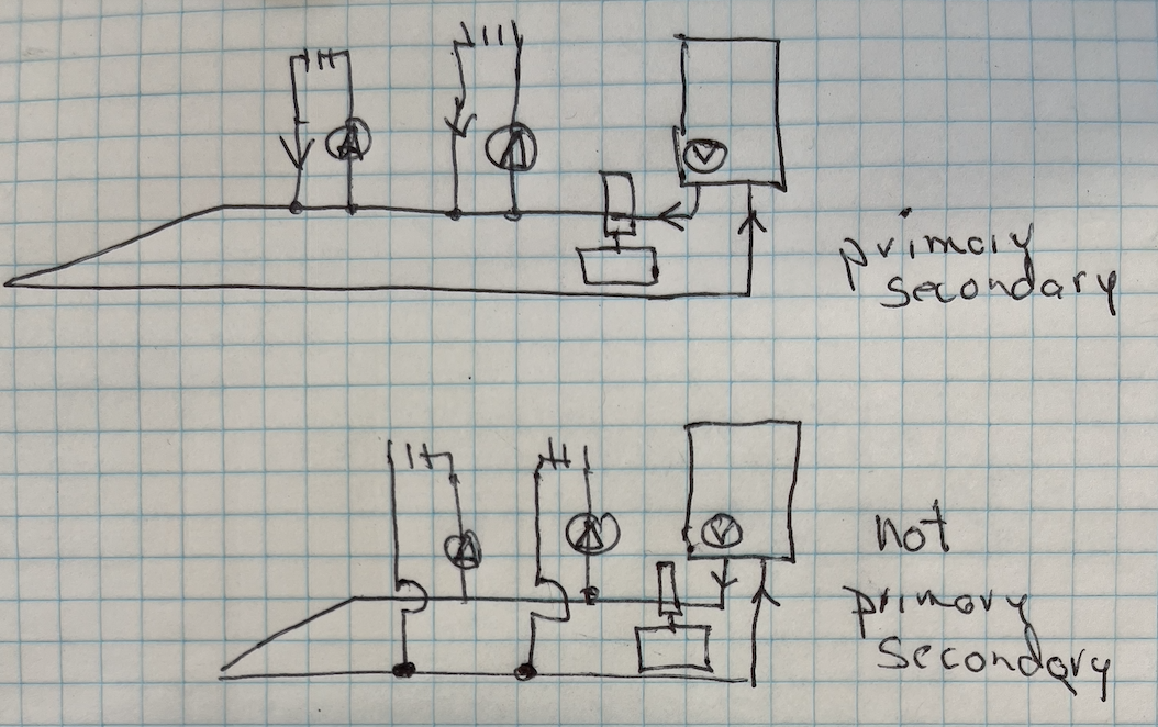
You are correct there are a numer of ways to pipe P/S. I put the 4 most common on the one slide.
The single slide shows the P/S with the boiler IN the loop. But with series P/S you need to account for the temperature drop each set of tees contributes. Math included on the slide. This is how I see the OP piping?
One small issue with the OP headers is the close tees, and the distance between the sets, it is not textbook. I suspect those are boiler pump headers not specific P/S headers as the tees look equal distance? It will work, a small potential to ghost the secondaries as the spacing between the "close tees" widens

But the golden rule of P/S is closely spaced tees. If you don't have properly piped closely spaced tees you don't have hydraulic separation/ P/S.
A hydraulic separator, properly constructed is a version of closely spaced tees. The spacing can be wider due to the large barrel dimension, 1:3 ratio. Velocity in the barrel is 1/9 of the branches. If it is built to the correct proportions. Not all are :)

 Bob "hot rod" Rohr
trainer for Caleffi NA
Living the hydronic dream 2
2 -
OK thanks so much @hot_rod
I can see what you are saying in the bottom system example that you attached above. I was not thinking of the return being right along side of the pump, I had it pictured in my head that it was kind of alternating front to back instead of going left to right around the headers. I see it clearer now in the drawing you supplied. I was over complicating it in my head.
0 -
One question @Kaos asked was flow direction? We need to know which model boiler. Are the connection locations different on the two combi models?
On this Navian combi, from the installation manual, the boiler out S, and boiler return R, are on opposite sides of the case. Center two connections are DHW.
In the OPs installation pics it look like the connection for heating are on the left? If so which is boiler S and boiler R? Hard to see from that camera angle.


 Bob "hot rod" Rohr
trainer for Caleffi NA
Living the hydronic dream1 -

Left side supply right side return...
0 -
So I just noticed in all the examples a mod con has manifold with closely space tee right away coming off the boiler but that doesn't mean mod con can't use the set up in the picture in question?
0 -
Pretty sure it's ncb 240…
0 -
Ok. The flow is the right way and the plumbing is proper primary secondary loop. You don't need the boiler on closed space Ts for this setup, what you have there is good.
Assuming no air lock and pumps are OK, maybe the issue is the way over pumped setup. If you turn off all the zones and only run the one that has no heat, does it work? If this works but when you turn on a zone upstream of it, you loose all heat, the problem is the previous zone is flowing too much and using the full capacity of the boiler. If this is the case, the easy fix is to throttle the pumps with the isolation valve on the outlet of it.
If running the zone by itself does not generate heat (assuming primary loop is hot), the problem is air locked zone, gummed up piping or bad pump.
1 -
can we get a better picture of the heating return into the boiler?this picture looks like it goes to the domestic hot supply outnevermind, I looked it up,
known to beat dead horses0 -
If the primary loop, those headers are 1-1/4" you can easily move 15-18 gpm through it. If the boiler and pump has that capacity you can move 150K. 19 gpm in 1-1/4 is only 4 fps, If the boiler circ can cover that flow and pressure drop.
The boiler manual often shows the HX flow rates and pressure drop related. Very little pressure drop in that small primary loop.
So the question is what can the 5 loops actually flow. What are the zones? Loops of fin tube?
Looks like 1- 1" loop and 4- 3/4"?
The 1" loop could flow 8-10 gpm. 4 gpm is reasonable, probably a high number for 3/4" fin tube loops.
So 8 gpm plus 4 at 4 gpm? would be 24 gpm potential load?
That primary loop probably would not cover those zone loads if they all call at once. If one is an indirect load, that could be on a priority. So then either a 20 gpm or 16 gpm load? That is doable with what you have.
If 2 & 5 zones operate properly, the primary loop if flowing at least 8 gpm, assuming 2- 4 gpm loads.
So as others have suggested, the primary loop, boiler pump, or boiler itself is constipated. Unable to deliver the full boiler output.
Run one loop at a time, valve off all the others. Do you get flow, heat, ∆T? Do that for every loop to eliminate the issue of a clogged or air locked loop.
In a perfect hydronic world you would have the info for what each zone requires in either gpm or btu/hr. That would save the guessing.
Another option is measure the radiation in every zone. Could be some only need 2 gpm, maybe a small 1 gpm load?
As the math in the example above shows, if in fact all 5 run at once, that last zone will see some very low SWT.
The mystery is it worked fine before?? What changed??
Bob "hot rod" Rohr
trainer for Caleffi NA
Living the hydronic dream1 -
Baseboard in basement but upstairs ci radiators.
0 -
As you know the heat delivery will be much different with those two types of emitters. If you are watching S&R delta T, the CI will take much longer from a cold start to warm.
If the CI rads are the last loops off the P/S piping they will be seeing a low temperature, further slowing the feeling of heat. The rads can be taking a lot of the gpm with the low pressure drop. If the rads are piped with 1" and a 007, they are taking a lot of your gpm, I'd choke the flow down to those. The ball valve at the circ is fine for some basic balance.
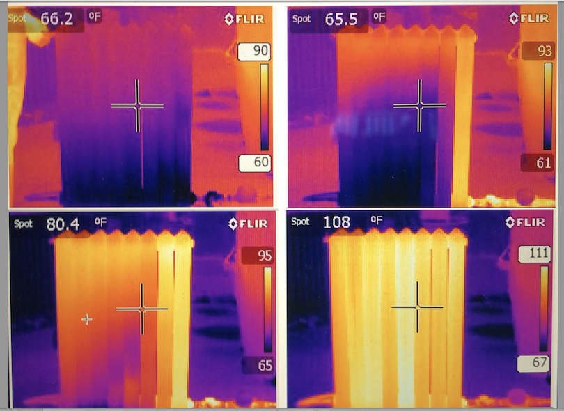
I ran this IR test at 2,4 and 8 gpm flow rates. No question the higher flows = quicker warm up higher btu transfer rate..
CI radiators make for good air traps and secondary PONPC locations, so good bleeders are helpful on the top of them.
Lots of time and patience, plus troubleshooting $$ to get a handle on a job with so many unknowns. Good luck, report back.
Bob "hot rod" Rohr
trainer for Caleffi NA
Living the hydronic dream0 -
Will do thanks again for all your time, help, and knowledge! I read about this as well in caleffi idronic fall 2024. Now I recognize a lot of these photos too! Thanks!
0


Categories
- All Categories
- 87.7K THE MAIN WALL
- 3.3K A-C, Heat Pumps & Refrigeration
- 59 Biomass
- 430 Carbon Monoxide Awareness
- 129 Chimneys & Flues
- 2.2K Domestic Hot Water
- 5.9K Gas Heating
- 122 Geothermal
- 170 Indoor-Air Quality
- 3.8K Oil Heating
- 79 Pipe Deterioration
- 1.1K Plumbing
- 6.6K Radiant Heating
- 396 Solar
- 16K Strictly Steam
- 3.5K Thermostats and Controls
- 56 Water Quality
- 51 Industry Classes
- 51 Job Opportunities
- 17 Recall Announcements