1930's Hydronic System help understanding
Comments
-
Thank you, @EBEBRATT-Ed !
0 -
Some of the B&G NRF series are close to that specA 3 speed NRF 25 maybe
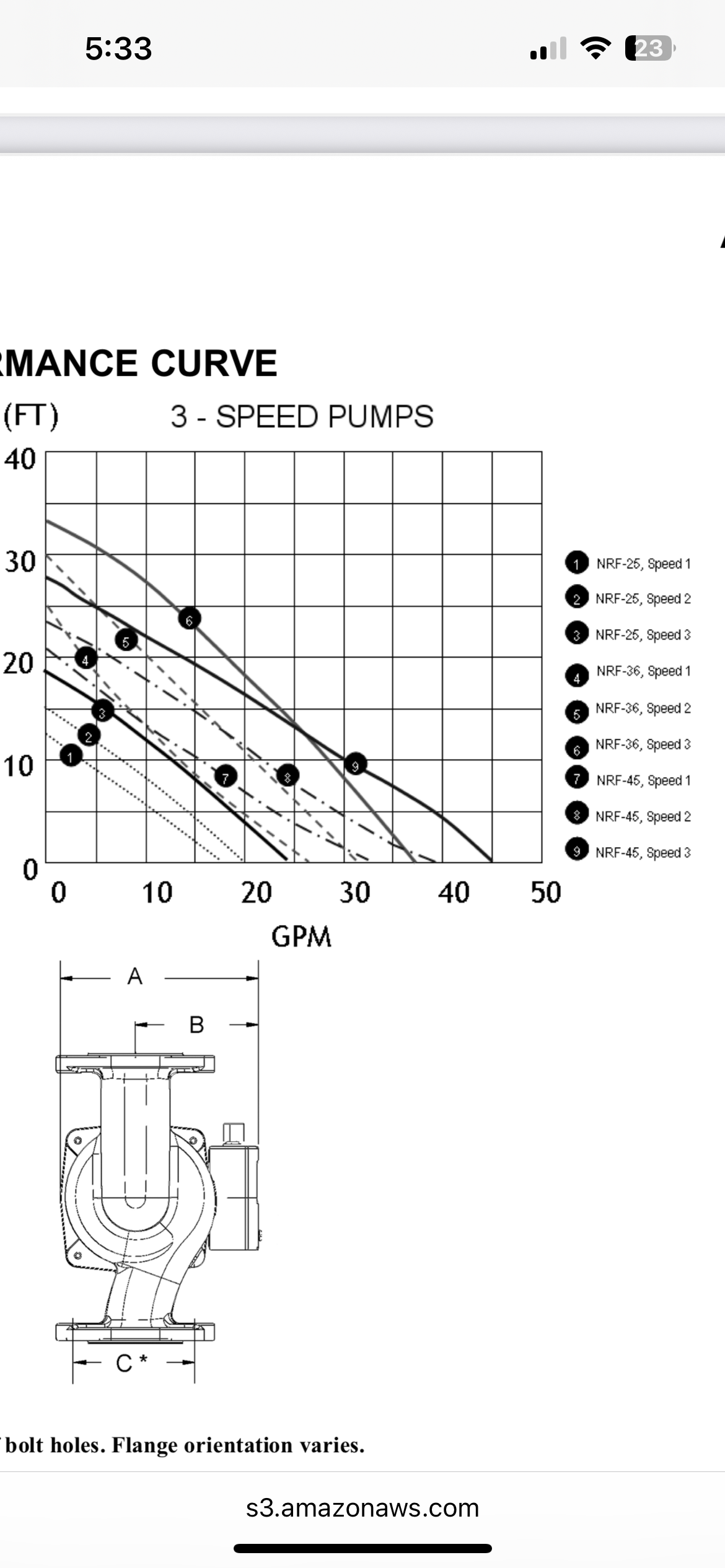
There used to be a LR series that was high flow low head. These are one piece wet rotor type circulators
Bob "hot rod" Rohr
trainer for Caleffi NA
Living the hydronic dream 1
1 -
Thank you, @hot_rod !
0 -
Thank you @hot_rod and @EBEBRATT-Ed. I did a bit of homework and have a few more questions, if you all are will to help.
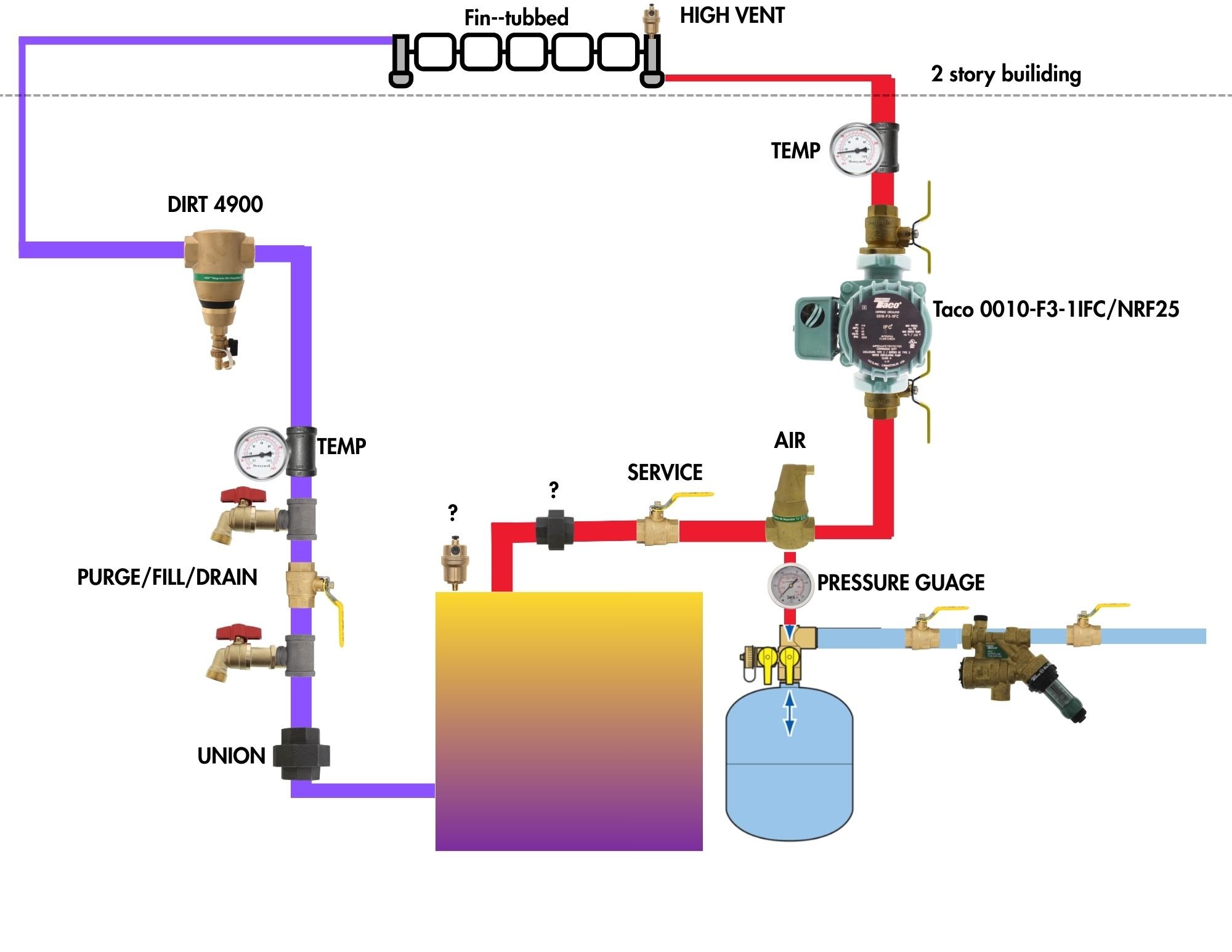
I made a mock-up of the proposed improvements based on your suggestions and others. Yet, not sure if I'm going a bit overboard here or I'm on the right track.
From what I've gathered, the most important considerations are:
- Air removal
- Pump Away
- Properly sized circulator (the ECM 0015 replaced the Series 100 and that is when issues starting arising with the 2nd story fin-tubbed heat emitters)
- near-boiler piping
- water quality
- Dirt/magnetite mitigation
- Purge/fill station
Questions:
- With a boiler of this age, should I spend the additional $$ on this re-pipe so the expansion tank and circ on on the supply side or save the $$/time and simply relocate the expansion tank to the tee that @mattmia2 suggested on the return?
- From what I have learned, tried to calculate, it looks like a flow rate of 14+ and a head of 7(ish) is needed. I have access to a Taco 0010 or a NRF25. Am I on the right track? (previous gravity conversion)
- I noticed there is a nipple with a cap on the boiler for a boiler vent. Should I add a float style automatic air vent or keep this capped? Obviously this has been capped since the installation…
- Should I place a high-vale type air vent on the top/2nd story radiators?
Thank you all for your help!
 0
0 -
If you are considering replacing the current boiler you could easily reconnect the steel compression tank and use it again.
My question to you is where are the tapping's on this steel compression tank? I do not see any tapping's based on the photo you provided.
1 -
Thank you, @leonz. The steel compression tank was left over from the previous boiler from many years ago and remains unused. Maybe this is a good time to remove that tank.
The current boiler does not use this tank and instead the EX60 expansion tank, etc..
0 -
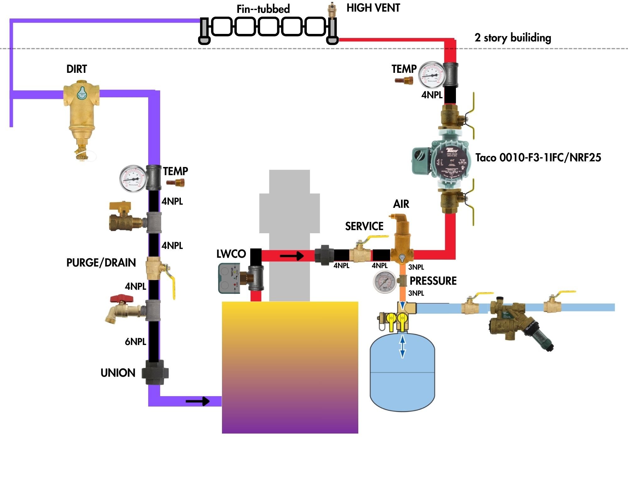
Revised layout. Adding a LWCO, thermowells and boiler union.
 0
0 -
The Low Water Cut Of Switch should be installed in one of the tapping's in the side of the new boiler and it should be wired as the first electric control to protect the boiler in the event of a water loss as it will immediately cut the power to the boiler if the LWCOS senses no water.
About the steel compression tank; it would be better and more effective keeping this tank for air management as it has a much greater capacity to create and maintain the point of no pressure change. The steel compression tank creates a huge air cushion to provide the Point Of No Pressure Change and quickly removes air bubbles and microbubbles as long as an In Line Air Separator and Airtrol valve is installed correctly.
Once the boiler, steel compression tank and system is filled with water the water feed valve is shut off completely and the boiler started the remaining air in the system will migrate to the steel compression tank dissolve from the water and will remain in the air blanket above the water in the steel compression tank to maintain the Point Of No Pressure change and keep the circulator flooded.
 1
1 -
It takes a lot more care to make sure the air stays in a compression tank than just collecting it and venting it. A bladder tank is smaller because it can be for the same system volume. I'd need to think a few minutes about the physics why, possibly just because it needs to start with the air cushion's volume at atmospheric pressure but a bladder tank can start with the compressed volume of the air cushion.
1 -


Categories
- All Categories
- 87.7K THE MAIN WALL
- 3.3K A-C, Heat Pumps & Refrigeration
- 59 Biomass
- 430 Carbon Monoxide Awareness
- 129 Chimneys & Flues
- 2.2K Domestic Hot Water
- 5.9K Gas Heating
- 122 Geothermal
- 170 Indoor-Air Quality
- 3.8K Oil Heating
- 79 Pipe Deterioration
- 1.1K Plumbing
- 6.6K Radiant Heating
- 396 Solar
- 16K Strictly Steam
- 3.5K Thermostats and Controls
- 56 Water Quality
- 51 Industry Classes
- 51 Job Opportunities
- 17 Recall Announcements