1930's Hydronic System help understanding

Hi everyone!
First time posting!
I'm trying to understand my hydronic heating system in my brick and plaster 1930s 4-plex building located in Ohio. Originally, the building had an oil-fired boiler, which was replaced in the late 1990s with a Weil-McClain (CG series) natural gas-fired boiler.
Here’s a summary of the current setup:
- Circulator Placement: The circulator is installed on the return line before it enters the boiler, rather than pumping away from it.
- Fill Valve/Cold Water Supply: This is also connected to the return line before the circulator.
- Expansion Tank: Positioned on the output side of the boiler.
- Air Separator: There doesn't seem to be one installed.
- Heat Emitters: All are fin-tubed with recessed radiator covers.
- Piping: The piping appears to be original. However, the pipes leading from the boiler are smaller in diameter compared to the larger main pipes feeding the branch circuits.
- Boiler Control: Managed by a Tekmar 256.
I believe the system is a type of 2-pipe setup since each heat emitter has both supply and return lines connecting to separate larger pipes. Most of this piping is visible in the basement, although it's unclear how it reaches the second floor.
Regarding the climate, the cold season lasts from November to February, with average daily high temperatures below 49°F. January is the coldest month, with average lows around 25°F and highs of about 40°F.
Recently, we had several updates and repairs:
- Boiler service
- The circulator was replaced with a Taco ECM (0015e3).
- The boiler gas valve was replaced with the same Honeywell model.
- A backflow preventer was added.
- Service/isolator valves and isolation flanges were installed on the circulator.
Since the latest circulator replacement, we've experienced issues such as no heat throughout the building or low heat in the second-floor unit furthest from the boiler. Each time, the installer would bleed the radiators, temporarily resolving the issue. I'm also uncertain if the Tekmar control is configured correctly. After reading more about the concept of "pumping away", maybe not using this technique is also contributing to bad performance?
I’ve been learning a lot from resources here and the HeatingHelp YouTube videos to understand this system better. My goals are to optimize the system for efficiency and save on winter heating bills. With the boiler aging and anticipating significant future expenses, I'm debating whether to maintain this hydronic system or explore other heating options.
Additionally, most of the heat emitters have shutoff valves. I'm considering whether adding Thermostatic Radiator Valves (TRVs) could be beneficial.
Lastly, this is a hard-water town. The system has always been filled with city water. We have had scale issue. I've read about properly treating the system water yet this has never been done or tested.
Any suggestions or advice would be greatly appreciated. Thank you!
Comments
-
If you can provide pictures that would help. If they did not install an air separator of some type that is a problem that needs to be corrected.
You may very well have more than one issue that needs to be tended to and corrected.
If you do not have a licensed plumber you rely for heating system maintenance you need to hire one as that is the first thing I would have you do as it sounds as if you have a heating oil dealer doing your heating system plumbing work-been there done that, bad idea.
Invest in several of the fine books that Mr. Holohan has written on hydronic heating and you will know what you are looking at and understand it.
Please wander over to the heating help bookstore page and there are many books you can purchase to learn more about hot water heating.
1 -
Thank you! Pictures to come! The technician was a licensed HVAC professional. More info soon. I'll check out the books, too!
 1
1 -
Your installer should have sold you an air removal device and done some re-piping so you are pumping away.
Two ways to pipe hydronic systems to deal with air:
Air Management vs. Air Removal
Older systems like yours and mine were set up for Air Management. They used a compression tank that had no separation between air and water. They worked OK, and were tolerant of not Pumping Away. They have an air scoop that directs most of the excess air into the compression tank. I still get away with it, but I'm a single family home and have easily bleed cast iron radiators on my second floor (where some of the air goes).
You are a four plex apartment, with harder to bleed fin tube. You will greatly benefit from Air Removal and pumping away. Properly piped, the system will be mostly self bleeding.
@AlwaysLearning2024 said: However, the pipes leading from the boiler are smaller in diameter compared to the larger main pipes feeding the branch circuits.
That just means your system was originally gravity circulation. I have that too. My house was piped in 1916. It works fine with smaller pipes coming from the boiler because it is now pumped. Works with both pumping away (best practice) and pump on the return (more bleeding chores).
Check this for Find a Contractor in Ohio:
0 -
Thank you! Super helpful! Curious if you use any thermostatic valves to help regulate individual heating elements?
0 -
Can you show us the expansion tank? It may be a conventional compression tank rather than a bladder type tank, if it is a conventional tank you can't have an automatic air vent, it will remove the air charge that is supposed to be in the conventional tank.
Is there any discharge from the relief valve?
Your original system was a gravity how water system, someone added a circulator at some point but it originally used gravity circualtion, that is why the pipes are bigger than the pipes to the boiler, they needed to be bigger to have enough flow with gravity. With a circulator the smaller pipe can move enough water to transfer the heat.
Since this system has a large water content if it was mostly drained there could be a lot of air to get out of the system.
The original boiler likely was coal fired and had an oil burner added at some point. Oil burners did exist in the 30's but were very uncommon.
0 -
And keep the hydronic system, just get it working properly, it will be far more comfortable than whatever you replace it with.
 2
2 -
Are your "fin tubes" in a cabinet about 3' wide by 2' high or so? If so they are convectors and are likely original.
1 -
Curious if you use any thermostatic valves to help regulate individual heating elements?
I don't, but I'm a single family home which luckily heats evenly. I also prefer simple systems.
As a four plex apartment, TRVs may be something your tenants would like. Without TVRs, if the tenants get too hot they may open the windows costing you fuel. Theoretically, if the valves worked, tenants could adjust their heat that way, but …
0 -
Thank you. I've been going back and forth about this. The boiler I know will need to be replaced in the near future. Always thinking if another solution would be better.
0 -
Yep! You got it! The covers a "bit" of a pain to remove and reinstall. Recessed into a metal cavity.
0 -
I snapped a few photos today. The tank in the ceiling is no longer used. Is this part of the gravity fed system?


 0
0 -
The tank in the ceiling was a compression tank. It can be used with a gravity or a pumped system. It coudl be original from the 30's but it looks newer liek ti was part of a later boiler replacement. Either type of tank can be used with either type of system. Your system would benefit from a microbubble air separator at the boiler, either a spirovent or a discal.
Did anyone check the precharge in the diaphragm tank? It needs to be checked with the tank isolated from the system. Does the relief valve dribble? Adding new water to the system because it is leaking or getting over pressurized because the expansion tank isn't working right will keep adding more air to the system.
Unless there is internal corrosion from a persistent leak and constant fresh water or something else we can't see, your boiler doesn't look like it needs replacing any time soon.
Pumping away is the preferred way to install a hydronic system and makes it easier to keep free of air but there are many systems set up like yours that work just fine, it was the older way of doing it.
1 -
Thank you! Relief valve is not dripping. Not sure on the pre-charge on the expansion tank. Good to hear that the boiler looks good. The main issue is radiator bleeding due to no-heat calls and a very hot building (unsure that the Tekmar boiler control is operating correctly)
If not moving the circulator to pump away, would I add a spirovent to boiler output near the expansion tank yet within a 18" straight run?
0 -
If not moving the circulator to pump away, would I add a spirovent to boiler output near the expansion tank yet within a 18" straight run?
I think that location would work. Ideally the air removal device goes in the hottest lowest pressure place in the system. In pumping away this would be after the boiler outlet, but before the pump/circulator. You are pump on the return, so I think your proposed location is your best option.
Your system looks good. It's odd there is no air removal device. With all the work your installer did, he should have repiped the near boiler piping to pumping away. Oh well. It will work the way it is. Just more work to get it bled. You may have to do some bleeding at the second floor radiators.
That Weil could have many years left. Run it until it leaks water.
0 -
With a conventional cast iron boiler the air tends to collect in the boiler itself where the water is hot and moving slowly so it isn't quite as good as pumping away but air elimination on the outlet of the boiler works well.
0 -
are there any best practices regarding the quality of the water? Should I be using some sort of treatment on the water? Testing the pH level? Is there an additive I need to use? I had one plumber tell me years ago that when they drain hydronic systems, they refill with soft water.
0 -
There are corrosion inhibitors you can add and demineralizing filters but it is much more important to make sure the system isn't leaking so fresh water with new oxygen and minerals isn't being added to the system
0 -
The first issue you have to fix is that your city water MU is on the suction side of the circulator and the expansion tank is on the discharge side of the circulator.
That one fact shows the installer didn't know what he was doing.
And as others have mentioned the circulator should be pumping away from the expansion tank not towards it.
But, there is an easy fix to solve both problems. Disconnect the expansion tank and plug the tee connected to the expansion tank.
Install the expansion tank into the same tee that the city water is now connected to. So both the expansion tank and the city water would be connected to the same tee the city water is presently connected to.
Then you will be pumping away. That's an easy job to do. The while the boiler is drained install a Spirovent (or another brand) air removal device.
2 -
Wonderful solution! thank you! Would I add the Spirovent on the output of the boiler? Maybe where the current Tee and expansion tank live?
0 -
I would prefer the air removal device up high where the union is on the supply pipe. It will work better and be easier to install there. When you move the expansion tank, I would put a boiler drain in that tee.
1 -
Is this what you are suggesting?
Expansion tank with air separator and MU at the same T?
 0
0 -
That is ok. But the air removal device should be on the supply coming out of the boiler. You have a perfect spot on the supply up high over the flue pipe where you have a union already installed.
1 -
Aha! Ok! I’ll see if I have the vertical clearance at that union up top. Curious if another spot could be the tee where the expansion tank lives now for the air separator?
or why it’s best to get the air operator up high.
Thank you!
0 -
the tee where the expansion tank is ok for locating the air seperator .
Consider a product that does air, dirt, and magnetic partial removal, especially with that circ.
 Bob "hot rod" Rohr
trainer for Caleffi NA
Living the hydronic dream2 -
Thank you! I'm starting to think that the previous work we had done (which included replacing the failing Series 100 circulator), wrong circ may have been chosen by the contractor (Taco ECM 0015E3F4)
Learning and reading more here especially about gravity conversions makes me think that the Series 100 (or the like) was the correct circ for the job which may be needing a higher flow rate.
The issues I had last winter after the circ replacement was low heat on the upper floor and especially the furthest away. Seemed they were trying to bleed as usual which helped for a bit and eventually were resolved. Yet, the heat was adjusted to much higher than I had ever used (I've been here 20 years).
I'm trying to sketch out the piping and hoping to post soon.
Also, is the capped pipe in the picture the "automatic air vent" for the boiler? Should this be capped or should there be an air vent added?
 0
0 -


Your problem could indeed, be the new pump. While the Taco can pump against a higher head, the B&G has a greater flow capacity. Calculate the head and GPM of your system and find your duty point on the charts to see which pump is the correct one.
8.33 lbs./gal. x 60 min./hr. x 20°ΔT = 10,000 BTU's/hour
Two btu per sq ft for degree difference for a slab1 -
probably not as much flow as needing different balance with the new circulator.
1 -
Good call! In the old days, they installed orifice plates in the upstairs radiator spuds on gravity systems because the hot water was buoyant and wanted to go there first. When you convert to a pumped system, the orifice plates get moved to the downstairs radiators.
I’ve never seen this around here, but Dan talks about it in his books.8.33 lbs./gal. x 60 min./hr. x 20°ΔT = 10,000 BTU's/hour
Two btu per sq ft for degree difference for a slab2 -
Thank you. Do you mean I don't need as much flow? Or that I should lower the speed on the circ?
0 -
I mean you don't need much flow to move the heat, you probably need to close down the valves or otherwise slow down the flow in radiators that heat too much so it pushes more flow to radiators that don't heat enough.
There may be orifice plates in the valve unions of the upper floor radiators that were part of the original gravity installation to reduce the flow at the top of the system and encourage more flow at the bottom of the system.
With a gravity system the hot water wants to rise to the top of the system and heat those radiators first.
Once you add a circulator the flow prefers the radiators closest to the boiler because of the forced circulation from the circulator wants to take the first available path.
0 -
You can also add thermostatic radiator valves (TRV's) to each radiator that will help with balancing the system.
8.33 lbs./gal. x 60 min./hr. x 20°ΔT = 10,000 BTU's/hour
Two btu per sq ft for degree difference for a slab 1
1 -
this ^^^^
0 -
Hi Alan,
Finally getting back around to this project. I followed some guidance here regarding calculating the head and volume of the system to ensure I have the correct circulator specs, yet curious if I'm on the right track.
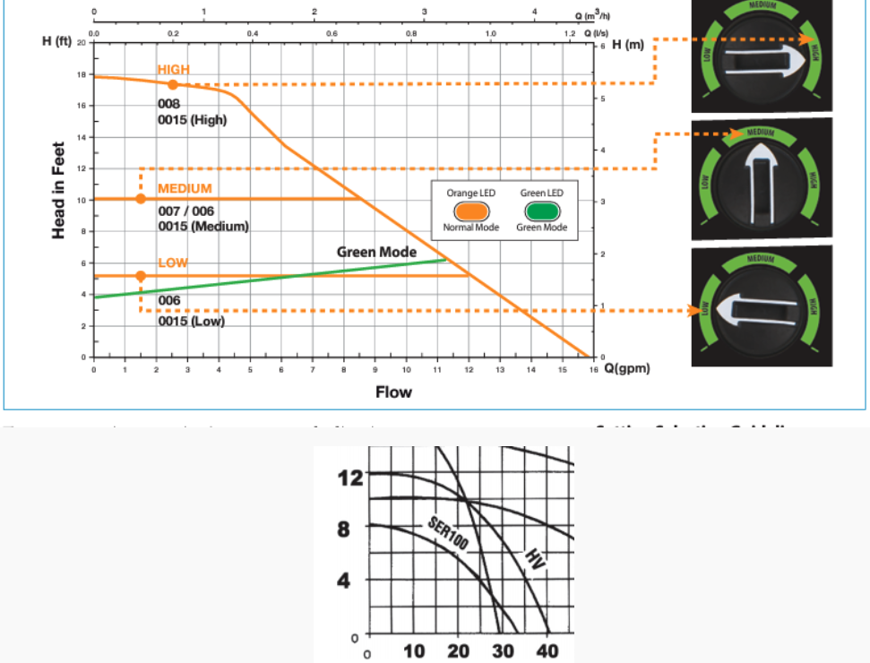
If this is close to correct, I think I would need a circulator that delivers around 14 GPM at 20 foot head? The height of the top floor radiator is 16 feet from the bottom of the boiler). The "new" circulator (Taco ECM 0015) that seems to be having trouble replaced a Series 100.
 0
0 -
Are you adding all those head losses together? You should just take the longest possible path and figure that as your head loss. Other parallel paths don't add head loss, they just add flow.
In any even, you don't need a pump to pump to the highest level (your 20 foot figure). All the circulator pump needs to do is keep the water flowing around the loops — so even if your head loss figure of four feet is right, that's all you need. Keeping the water in the system up to the highest point is taken care of by the static pressure in the system — and the usual 15 psig would be enough.
Br. Jamie, osb
Building superintendent/caretaker, 7200 sq. ft. historic house museum with dependencies in New England 2
2 -
Thank you, Jaime. Very helpful!
Yes, it seems I was taking into account each unit and the losses incurred, which I'm guessing is not correct.
Is psig the same figure as GPM in regards to circulator specifications?
Would my longest possible path would equal the length of piping from from boiler to the furthest radiator? (I'm still not certain on how this building was piped i.e. reverse return, etc..).
If only having a 4 foot head loss and 15psig, it would seem the Series 100 specs meet this criteria much better than the Taco 0015. Or am I off base?

 0
0 -
The only thing you need to calculate is the water circuit with the highest resistance to flow. Building height means nothing. PSI means nothing. Find the circuit that has the most resistance at the flow it needs. That is the head the pump needs to overcome. Then use that head with the total flow you need for all circuits.
2 -
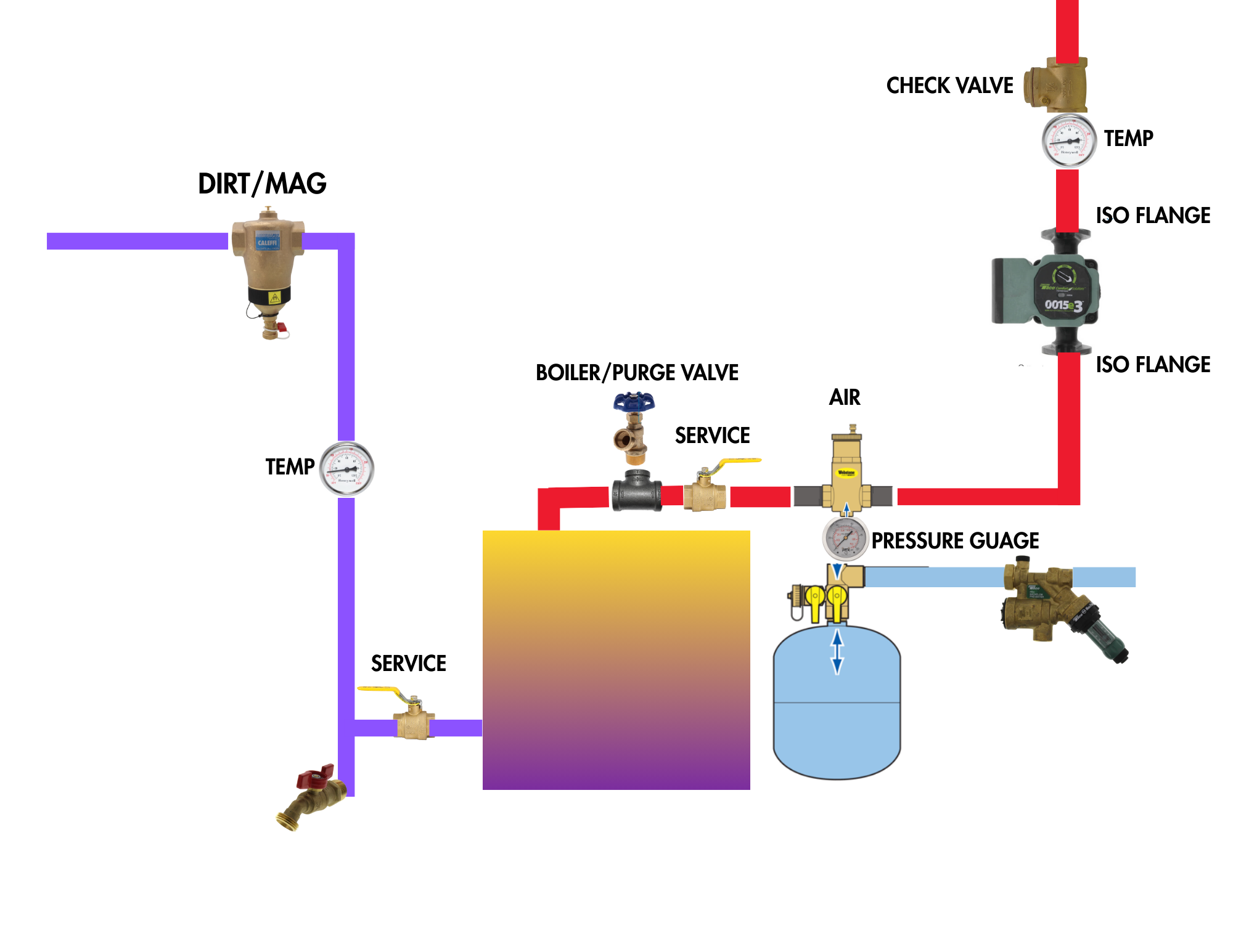
Hi @hot_rod and @EBEBRATT-Ed, circling back on this project. If I was able to re-pipe and add some elements, am I on the right track with this photo of a design? Thank you for any guidance!
 0
0 -
Looks Ok. You may not need the check valve if there is one in the circ.
1 -
Piping looks good. You probably do not need the purge valve above the boiler, the air purger takes care of that.
I'm still not sure that 0015 is the best circ for the job.
Ideally you want a circ to run mid curve. The B&G was a near perfect choice. The 0015 is near run out on the curve. If 14 gpm @ 4' is what you need?
 Bob "hot rod" Rohr
trainer for Caleffi NA
Living the hydronic dream1 -
Thank you, @hot_rod !
The purge valve was a recommendation I noticed from @DanHolohan in one of his Pumping Aways videos. I may have misunderstood.
The switch to the Taco 0015 was initially related to the Series 100 noise, wattage and occasional impeller replacement. I was hoping the installer was choosing the correct replacement yet that seems to not be the case. Aside from going back to the Series 100, do you have a recommendation on another circulator choice? Maybe a 007 or Grundfos Super Brute 15-58?
0


Categories
- All Categories
- 87.7K THE MAIN WALL
- 3.3K A-C, Heat Pumps & Refrigeration
- 59 Biomass
- 430 Carbon Monoxide Awareness
- 129 Chimneys & Flues
- 2.2K Domestic Hot Water
- 5.9K Gas Heating
- 122 Geothermal
- 170 Indoor-Air Quality
- 3.8K Oil Heating
- 79 Pipe Deterioration
- 1.1K Plumbing
- 6.6K Radiant Heating
- 396 Solar
- 16K Strictly Steam
- 3.5K Thermostats and Controls
- 56 Water Quality
- 51 Industry Classes
- 51 Job Opportunities
- 17 Recall Announcements