Welcome! Here are the website rules, as well as some tips for using this forum.
Need to contact us? Visit https://heatinghelp.com/contact-us/.
Click here to Find a Contractor in your area.
If our community has helped you, please consider making a contribution to support this website. Thanks!
Hydronic design question, replacing NG boiler, diagram included
Options

JohnnyCB
Member Posts: 25
Hi All,
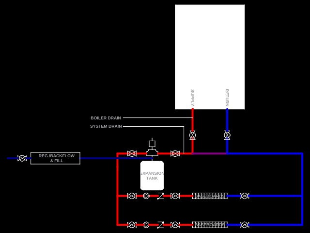
I am designing a new system to replace a failed one. Pretty simple setup - two zones (baseboard radiators on two floors), with a stub-out in case I add another zone for DHW or heat. Since the current boiler died, I have moved the DHW to electric so it's not a huge necessity at the moment.
So, I am considering the Bosch ZBR 28-3 Greenstar 100. Here's the piping design I'm considering:
My questions are:
1) Does this look reasonable?
2) Should there also be some kind of check valve on the return size of the zones?
3) Are there any other serviceability considerations I should include?
4) Since the zones are fed by pumps, I don't need a primary loop circulator, correct?
Thanks for any input!
0
Comments
-
It looks fine.
A check valve on the return would be good if the baseboard is above the boiler level.
A hose bibb between the air eliminator and the upstream isolation valve would make purging a snap.
Your boiler comes with a primary loop circ.8.33 lbs./gal. x 60 min./hr. x 20°ΔT = 10,000 BTU's/hour
Two btu per sq ft for degree difference for a slab0 -
A bit better air elimination would be a vertical air sep in the line from the boiler. It will see the highest temperature in the system. Once you are downstream of the closely spaced tees the temperature is blended. Not a huge deal. Wherever you put it, use a microbubble type air purger not a scoop type.
A combination dirt/ magnetic separator is a good addition. In the blue return. pipe somewhere before it hits the boilers.
Better yet, Option 2, use a hydraulic sep instead of the close tees and get a 4 function device. Air, dirt, magnetic, and hydraulicBob "hot rod" Rohr
trainer for Caleffi NA
Living the hydronic dream 1
1 -
The boiler has an internal circulator, but you don’t wanna pipe like that. Use closely spaced tees the way the installation manual shows and place the system sensor down stream of the tees.
The way you have it now, the system circs are in series with the boiler circ.Bob Boan
You can choose to do what you want, but you cannot choose the consequences. 1
1 -
@hot_rod Where would you put the expansion tank in your screenshot? Just before the system pump?8.33 lbs./gal. x 60 min./hr. x 20°ΔT = 10,000 BTU's/hour
Two btu per sq ft for degree difference for a slab0 -
I like the new tag line you have

So here are my suggestions for expansion tank location. Simple choice with a sep, either of the lower connections. Actually guys, and gals do put it off the bottom of seps, but throw a tee below the sep and put the tank off the branch. This prevents dirt from dropping down on the diaphragm.
A but more of a compromise with closely spaced tees. On the boiler loop is great with high pressure drop boilers as the boiler is first to see the delta P the circ adds.
Remember the teachings of Gil and Dan. WHEREVER you connect the tank into a system, that becomes the primary loop, by definition.
So on the boiler side of the "tees" makes the boiler loop primary. On the distribution side of the "tees" turns the distribution into the primary loop.
In reality does it make a huge difference? We could, and probably will debate that for generations")
If you wanted to analyze every piping system you encounter you could build a graph like this to "see" what is actually happening with pressure differential ∆P in the piping.
The red dashed line, see how it drops everytime you flow across anything. Not much droop going through the short pipe section in the second column. A big hit going through the "Munchkin", column 3. Impossible to be a pressure change at the exact point the expansion tanks connects, column 4 beginning, but more drops as we flow through pipe after the tank connection.
Another big hit going across an indirect with maybe a small copper coil, think early Amtrol type tanks.
So you'd need to analyze ever inch of pipe, every fitting, ball valve, whatever the fluid flows through to get exact profiles.
For non-engineer, minimum wage guys like you and me, as long as pressure doesn't drop well below static fill or below 0, negative anywhere in the system, mission accomplished. But only gauges, analyzing. Or I suppose years of practical experience will get er done.
On a weekly basis here we see the fruits of not knowing or paying attention to what the circ is doing, or not, in a system,.Bob "hot rod" Rohr
trainer for Caleffi NA
Living the hydronic dream0 -
It was a simple question.
Your mind goes where mine has never gone and I will copy and paste your answer and hang it over my computer for further study and dissemination.Thank you for taking the time!8.33 lbs./gal. x 60 min./hr. x 20°ΔT = 10,000 BTU's/hour
Two btu per sq ft for degree difference for a slab0 -
A HUGE Thank You to all of you! I will incorporate your suggestions.1


Categories
- All Categories
- 87.7K THE MAIN WALL
- 3.3K A-C, Heat Pumps & Refrigeration
- 59 Biomass
- 430 Carbon Monoxide Awareness
- 128 Chimneys & Flues
- 2.2K Domestic Hot Water
- 5.9K Gas Heating
- 121 Geothermal
- 170 Indoor-Air Quality
- 3.8K Oil Heating
- 79 Pipe Deterioration
- 1.1K Plumbing
- 6.6K Radiant Heating
- 396 Solar
- 16K Strictly Steam
- 3.5K Thermostats and Controls
- 56 Water Quality
- 51 Industry Classes
- 51 Job Opportunities
- 17 Recall Announcements