Indirect Water Heater installation: preventing gravity circulation
My building is large, two-story brick, all cast-iron radiators. Currently one circulator pump for the whole house.
I'm planning to basically follow the piping configuration shown in the manual that came with the heater (see picture). I planned to add one circulator to create a new zone for just the DHW. I got a taco relay to deal with the electric.
However, I'm a little confused by the circulator on the right side of the drawing, and a little confused about where check valves (and/or circulators that include check valves) ought to go. That circulator, on the return side, is between the boiler and where both zone loops end. If that's where you place the circ, doesn't it mean that the pump on the DHW would cause the other loop to flow?
Additionally, if the DHW is calling for heat, and the other loop is quiet, will the other circulator interfere with the DHW loop flow?

Comments
-
Hi, I see two parts to this. One is gravity circulation and the other is induced flow. Gravity circulation, (hot water floating on cold water) can be taken care of with heat traps, which are just bends in the pipe, at least six inches deep, that prevent gravity flow, or convection. The induced flow is where pumping in one circuit creates flow in another. Often you can prevent the induced flow by making sure that both ends of the circuits are not tied together, like taking cold from the same port in a tank and returning bout circuits to the same hot port. I've avoided the problem by separating one end, hot or cold, so the "off" circuit doesn't see any real pressure differential. Spring check valves can be your friend too! Just install them so you can get to them to check and maintain. Does that help?
Yours, Larry0 -
Hey Larry, thanks very much for your response! Yes, that is helpful. First, I think I'm talking about induced flow moreso than gravity flow. Thanks for calling out the distinction. To be more specific, maybe it would help to show what I'm thinking:
In this picture, the arrow is pointing to where I'm thinking about moving the existing circulator, and on the right is where I'm thinking to put the new circulator to the DHW. Or something like this anyway.
If I assume that both circulators have built-in check valves, that should work to prevent induced flow, right? I haven't taken the existing circulator apart yet, but if it doesn't already have a check valve it looks like one can be purchased for around $10 for this old Bell & Gossett circulator. The new circ has one built in already.
Thanks for any and all advice!
PS. One last question is: the indirect water heater specifies all 3/4 copper pipe. Does it make sense to plumb through the new circulator with 1-1/4" and then to reduce to 3/4" after the circulator? 0
0 -
I don't like the diagram . I see if the circulator for the heat pulling in it will circulate though the indirect . It states using zone valves . I don't see them..
There was an error rendering this rich post.
 1
1 -
Hey Big Ed, the top of the sheet (Figure 1, that I’ve cut off) has a diagram for zone valves. The bottom, Figure 2, is for circulators.It sounds like you’re saying the same thing that I’m concerned about: that piping the way the diagram shows will cause induced flow in whichever loop is “off” while the other one is on.
I want to keep things as simple as possible without causing problems. Does the photo and description I shared above make more sense as a way to eliminate induced flow?
Or what advice do you have for the plumbing?
Thanks.0 -
Another option is a single circulator with zone valves. Zone valves on the supply give you 100% close off for both ghost and induced flow. With an ECM delta P circ you add even more benefit.
Those weighted flo checks add a lot of pressure drop to ma circuit. A hydronic spring check might be a better choice.Bob "hot rod" Rohr
trainer for Caleffi NA
Living the hydronic dream0 -
garbage piping diagram. multiple issues. almost an unbelievable diagram. did you piss someone off and they sent you that piping plan so you would mess it up purposely. good luck with air control on that thing.0
-
@MikeAmann haha, wow. That’s a lot of reference points! Thanks very much for sharing.I think the first 3 diagrams you’ve posted basically confirm what I’m thinking. I’ve been reading about flow check valves (Taco 220 in diagram 2) and swing check valves, and I’m a little unclear on the application differences, but it seems like some kind of check valve on the supply side of the heating loop might be a good addition.0
-
@hot_rod I appreciate the zone valve idea. I already bought a Taco 007e ECM cast iron circulator, after considering both options. Not sure it’s the better option but it seemed like a similar price point, and possibly more durable?
The one thing I’ve learned from reading these forums is that there are 50 different ways to do everything. 🙂 1
1 -
No one has brought up the issue with many of these diagrams. It is best practice to design this so you are "pumping away" from the expansion tank.
To prevent ghosting, put check valves on the boiler side circulator and pipe heat traps on the domestic side."If you can't explain it simply, you don't understand it well enough"
Albert Einstein1 -
@levient
Ask a question get 100 different ways to do the same job. If you install another circ. you need check valve or flow checks and additional shut off valves and a relay for the 2d pump
If you use (2) zone valves you will need zone valves shut off valves and only low voltage wiring.
6 of one half a dozen of another.
Both ways work equally well.
I would use 1" pipe to the indirect0 -
@EBEBRATT-Ed re. your last comment, the indirect has all 3/4" interfaces, for DHW and supply/return. Does it make sense to run 1" most of the way to the tank before reducing? Or does it not really matter where the reducing happens?
Honest question, there are some basics of fluid dynamics I'm unfamiliar with.0 -
Ok, this is a lot to digest and I didn't go in to reading it in great detail. So...I will make one comment. Your original drawing shows an expansion tank on the domestic cold water feed to the indirect tank. There is no need for that Ex tank if there isn't a spring loaded check valve installed between the shut off valve and the Ex tank.
Later diagrams show the check valve, but use a spring check and not a swing check if using a Ex tank.1 -
What indirect do you have? If the coils or the tank connects are only 3/4 or smaller in some brands, really no reason to use 1" pipe, save some $$.Bob "hot rod" Rohr
trainer for Caleffi NA
Living the hydronic dream0 -
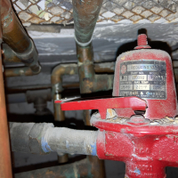
Clever use of the pump flange bolt!Bob "hot rod" Rohr
trainer for Caleffi NA
Living the hydronic dream0 -
Looking at the original picture of the pipe diagram shows "All Pipes 3/4 inch". This will restrict the amount of boiler heat that can go to the DHW tank heat exchanger. Rule of thumb on 3/4" pipe is about 40,000 BTUh. With the ECM pump and the short amount of piping you might get 45,000 or 50,000 BTUh to that tank. Why not up the pipe size to 1" copper and double the amount of boiler capacity that can get to the tank?
I also don't like the piping diagram first posted, You need to have check valves to prevent flow from one zone (heating) to the other zone (DHW) when the opposite pump is idle. But that was thoroughly covered previously.
Mr. Ed
EDIT: here is a book you can read to help you with the concepts referred to herein. http://media.blueridgecompany.com/documents/ZoningMadeEasy.pdf
Page 5 has pipe size as compared to BTU capacity.
Page 9 cover flow-control valves
Page 11 covers zoning with circulators.Edward Young Retired
After you make that expensive repair and you still have the same problem, What will you check next?
0 -
I hear you on the 1” pipe, @EdTheHeaterMan. But the water heater has 3/4” inlets, both DHW and boiler supply/return.
Thanks for the zoning book, I’ll check it out!
@hot_rod it’s a Burnham Alliance LT 80gal: https://s3.amazonaws.com/s3.supplyhouse.com/product_files/Burnham-AL80LT-Install.pdf0 -
The manual shows 6 gpm for the coil, so 3/4 is just about ideal, 6.5 gpm at 4 fps velocity with the chart at SupplyHouse
Difference in the various pipe sizer charts, the most accurate are at engineerintoolbox.con. The give you the choice of K, L or M copper if you want exactBob "hot rod" Rohr
trainer for Caleffi NA
Living the hydronic dream1 -
Still use the 1" pipe. The heat exchanger will accept more BTUh if you do. I know that it does not make sense, but it was explained to me long ago and I don't remember the actual formula like some of the engineers herein. But if you have less restriction in the approach piping and return piping, because the pipe is larger, the heat exchanger in the tank will get more actual flow.levient said:I hear you on the 1” pipe, @EdTheHeaterMan. But the water heater has 3/4” inlets, both DHW and boiler supply/return.
Thanks for the zoning book, I’ll check it out!
@hot_rod it’s a Burnham Alliance LT 80gal: https://s3.amazonaws.com/s3.supplyhouse.com/product_files/Burnham-AL80LT-Install.pdfEdward Young Retired
After you make that expensive repair and you still have the same problem, What will you check next?
1 -
If the tank is next to the boiler, the pressure drop difference in a few feet of 1" pipe would not amount to much. I doubt you would double the gpm? If the tank was a distance from the boiler it might be worth the $$ to go 1".EdTheHeaterMan said:
Still use the 1" pipe. The heat exchanger will accept more BTUh if you do. I know that it does not make sense, but it was explained to me long ago and I don't remember the actual formula like some of the engineers herein. But if you have less restriction in the approach piping and return piping, because the pipe is larger, the heat exchanger in the tank will get more actual flow.levient said:I hear you on the 1” pipe, @EdTheHeaterMan. But the water heater has 3/4” inlets, both DHW and boiler supply/return.
Thanks for the zoning book, I’ll check it out!
@hot_rod it’s a Burnham Alliance LT 80gal: https://s3.amazonaws.com/s3.supplyhouse.com/product_files/Burnham-AL80LT-Install.pdf
What if I supplied it with a 2" pipe? Even more output?
Seems the bottleneck is the coil diameter? Which I suspect may even be a 5/8" tube. The chart shows the pressure drop at 6 gpm. Increasing SWT a few degrees would be an option for increasing tank performance.
I've never understood the top coil only tanks. The cold enters the bottom of the tank, seems like the best delta as the tank depletes is at the bottom. If the coil is in warming water at the top, transfer drops.Bob "hot rod" Rohr
trainer for Caleffi NA
Living the hydronic dream1 -

For what it's worth, we have taken the opposite tack with IWH's. By "close-coupling" alongside our convection-enhanced Appliance we create a de facto priority loop as shown in the pic. A circulator failure should it occur enables auto-convection with no DHW service interruption as well as reduced convection heating, as req'd. We typically use 8 to 13 watts on our enhanced convection distribution circuits.
Note that we tee immediately above our dedicated Delta-T Circulator via a Zone Sentry and return to the lower rear boiler tap.
0 -
If the zone sentry were to fail do you get flow just to the indirect? Would it auto convect above aquastat setting?Labenaqui said:
For what it's worth, we have taken the opposite tack with IWH's. By "close-coupling" alongside our convection-enhanced Appliance we create a de facto priority loop as shown in the pic. A circulator failure should it occur enables auto-convection with no DHW service interruption as well as reduced convection heating, as req'd. We typically use 8 to 13 watts on our enhanced convection distribution circuits.
Note that we tee immediately above our dedicated Delta-T Circulator via a Zone Sentry and return to the lower rear boiler tap.
Is the circulator pumping at the expansion tank?Bob "hot rod" Rohr
trainer for Caleffi NA
Living the hydronic dream0 -
Hey folks, I really appreciated everybody's feedback on this project. I finished everything back in August, but if y'all are interested, I thought I'd finally post some pics. I did make a few small mistakes that I'll fix this summer. A tiny pinprick leak in one pipe, unnoticeable until the heating pump kicks on.
One more mildly annoying thing is that the check valve I added to the original zone chatters a bit. I wonder whether it's because the new pump is a variable speed.
Maybe I'll start another thread with a couple residual questions.


0 -
Could be the way the circs are bullheaded, pumping at one another? Chattering checks are usually do to insufficient flow to hold them completely open.
Bullhead is okay on water piping, not so ideal on hydronic piping, the flow doesn’t always split properly especially if the circs are stopping and starting under different heat calls.
Same on the supply piping, another bull head connection there.
Those pump checks “pop” at .35 psi typically, so somehow you are dropping below that.
Where is the expansion tank connected?Bob "hot rod" Rohr
trainer for Caleffi NA
Living the hydronic dream0 -
Ah, that makes sense re. the bullheaded junction, @hot_rod. I’m not sure how I could’ve otherwise plumbed it exactly given the space constraints.
Is there anything that might help the chatter short of completely reconfiguring the plumbing?
The expansion tank is on the portable water I think. The boiler tank is on the ceiling to the right of the boiler. I didn’t touch that one.0 -
A tee and an ell is one way to avoid the bullhead
That air purger would like 18” of straight pipe on the inlet also, it’s not doing much in that close connection.
A micro bubble type purger would fit in that space and get you 99% air elimination efficiency
A few repipe suggestions, add a micro bubble purger, connect the expansion tank below it. Install the circulators after that purger/ tank combination, so you pump away. Correct the bull heads at the same timeBob "hot rod" Rohr
trainer for Caleffi NA
Living the hydronic dream2


Categories
- All Categories
- 87.7K THE MAIN WALL
- 3.3K A-C, Heat Pumps & Refrigeration
- 59 Biomass
- 430 Carbon Monoxide Awareness
- 129 Chimneys & Flues
- 2.2K Domestic Hot Water
- 5.9K Gas Heating
- 122 Geothermal
- 170 Indoor-Air Quality
- 3.8K Oil Heating
- 79 Pipe Deterioration
- 1.1K Plumbing
- 6.6K Radiant Heating
- 396 Solar
- 16K Strictly Steam
- 3.5K Thermostats and Controls
- 56 Water Quality
- 51 Industry Classes
- 51 Job Opportunities
- 17 Recall Announcements