Welcome! Here are the website rules, as well as some tips for using this forum.
Need to contact us? Visit https://heatinghelp.com/contact-us/.
Click here to Find a Contractor in your area.
If our community has helped you, please consider making a contribution to support this website. Thanks!
Need help with Honeywell MCBA14201D controller troubleshooting
Options

ChucksOldBoiler
Member Posts: 14
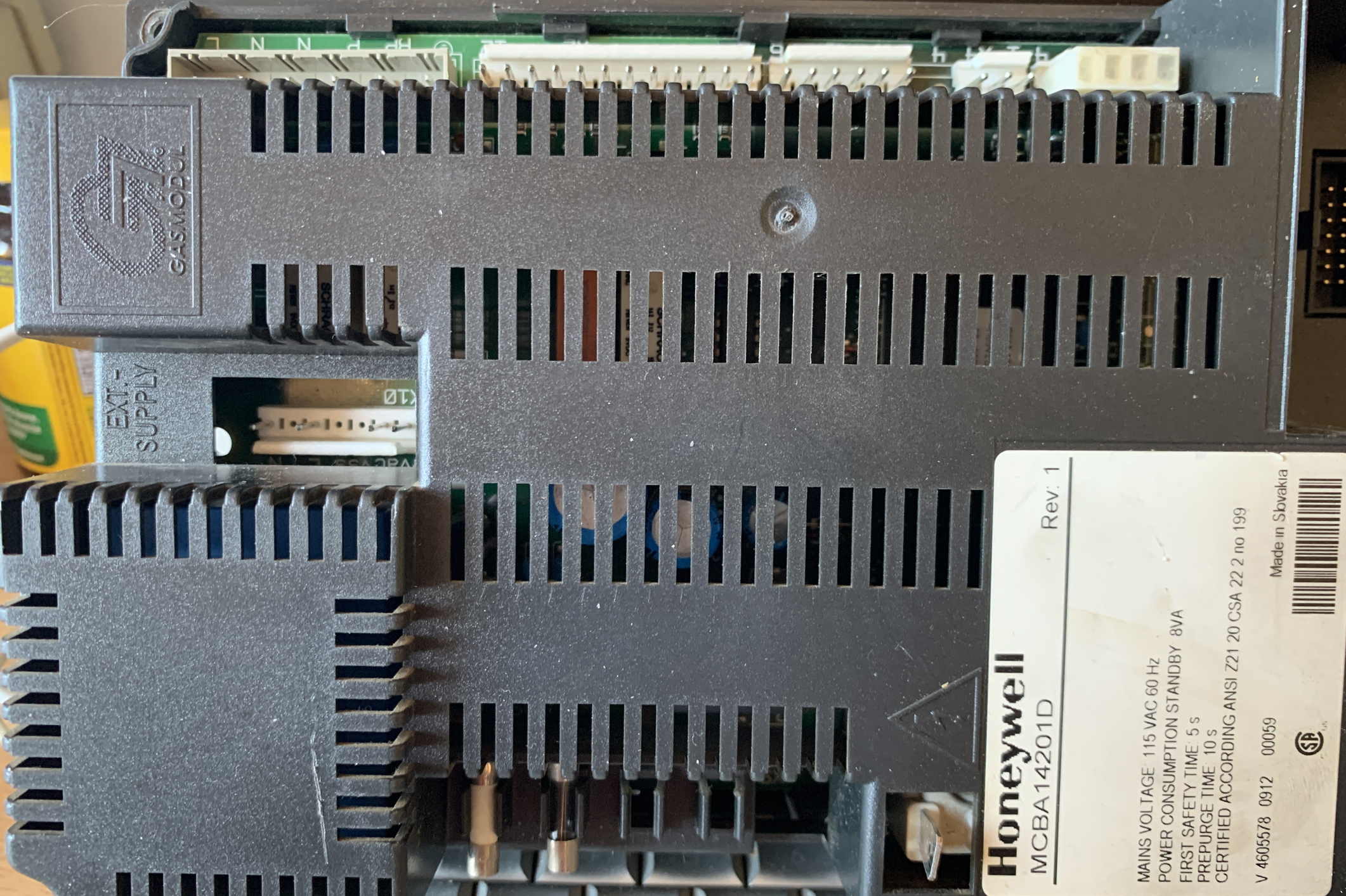
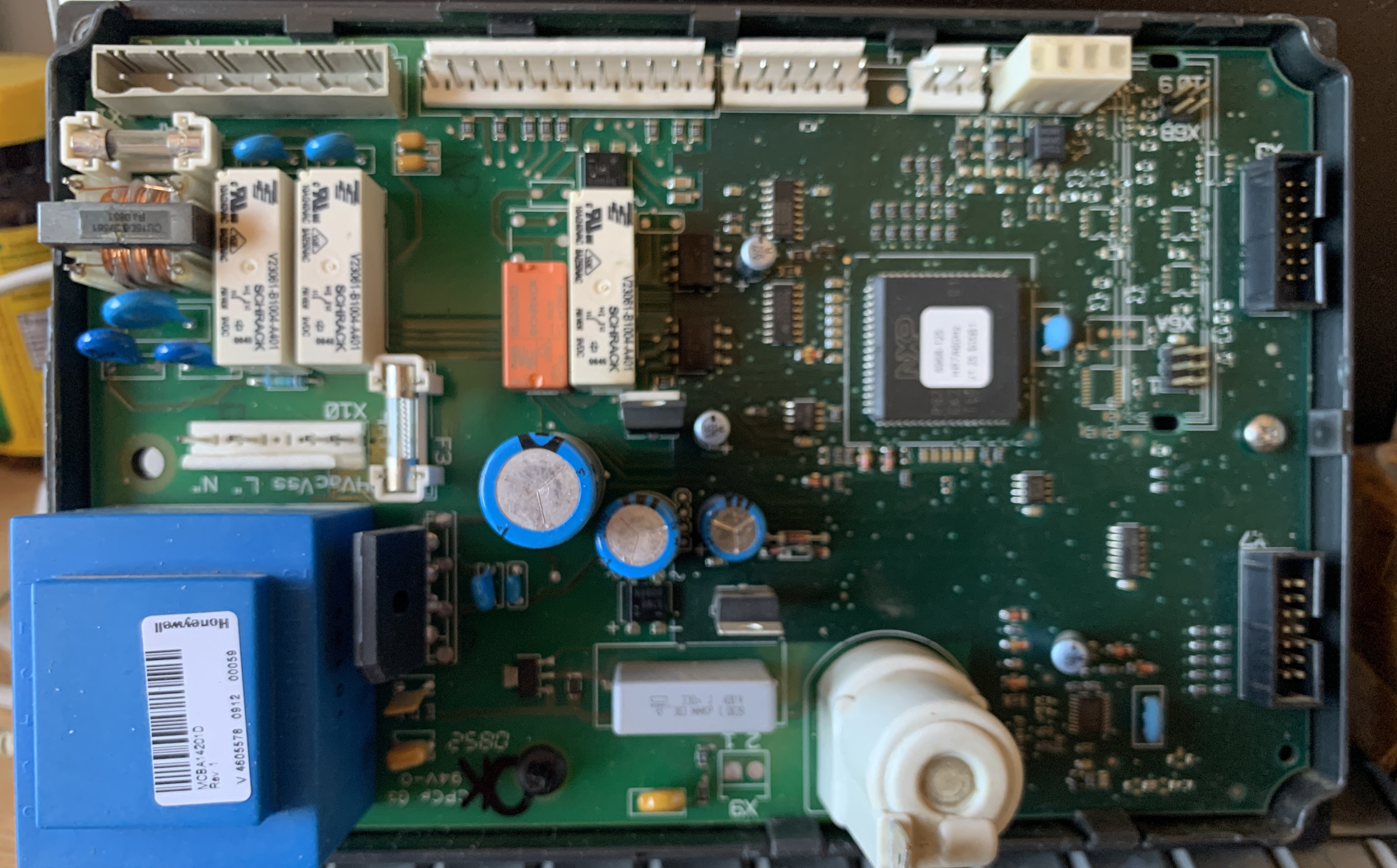
I have a Honeywell MCBA14201D controller board.
With the X2 connector removed There is 27vac on X2-10
When I connect a jumper across X2-10 to X2-9 there is no longer any voltage!
What should I expect to see on X2-10 Should it be AC or DC?
A technical manual w/schematic would be useful.
Thanks, Chuck
With the X2 connector removed There is 27vac on X2-10
When I connect a jumper across X2-10 to X2-9 there is no longer any voltage!
What should I expect to see on X2-10 Should it be AC or DC?
A technical manual w/schematic would be useful.
Thanks, Chuck
0
Comments
-
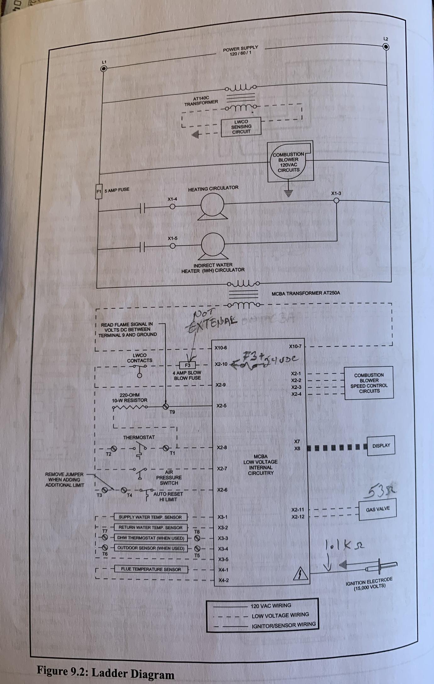
voltage referenced to what? Ground? I would expect AC X2-10 looks like either a common hot. The LWCO contacts -- or the fuse -- in that line will then remove power from the other signal circuits if either one is open. If that is so, X2-6, 7, and 8 have to high for the system to fire (Note that is X2-10 is grournd, the idea is somewhat similar -- but the other three have to be pulled low to fire).Br. Jamie, osb
Building superintendent/caretaker, 7200 sq. ft. historic house museum with dependencies in New England0 -
Hello @ChucksOldBoiler,
In my opinion the drawing is drawn a bit poorly, lacking some information and clarity.
I would expect 24 VAC between X10-6 and X10-7 from the transformer plugged into X10.
I would also expect to see 24 VAC between X2-10 and X10-6 or 24 VAC between X2-10 and X10-7, also X10-6 or X10-7 maybe referenced to ground or the units housing (although they don't show a ground except the return path for the ignition electrode, and the note for T9).
If you have a 24 VAC between X2-10 and X2-9, I would check the LWCO contact and wiring and the LWCO itself. I would check the Fuse F3 also (although it appears to be actually on the MCBA board and if Fuse F3 were blown you probably would not have Voltage across X2-10 and X2-9)
It appears the LWCO device has its own transformer for Low Voltage AC power. If the LWCO device is dead or has otherwise failed, you would probably see 24 VAC between X2-10 and X2-9 (LWCO contacts are open).
It looks to me like the 120 VAC line voltage is applied to the MCBA board, the BLUE box is a transformer that powers the electronics. The transformer plugged into X10 powers the safety sensors and stuff like that. If the LWCO contact is open or Fuse F3 is open due to wiring fault the 24 VAC is no longer fed to the various sensors and the unit is disabled.
When doing this " When I connect a jumper across X2-10 to X2-9 there is no longer any voltage! " Does it restore operation ??? If so, (since it appears Fuse F3 is actually on the MCBA board) I would go in the direction of the LWCO and its associated wiring and power. If it blows Fuse F3 check for a short to ground with all sensors and their wiring. Or does nothing different happen ???
I doubt we'll find a schematic of the MCBA board.
National - U.S. Gas Boiler 45+ Years Old
Steam 300 SQ. FT. - EDR 347
One Pipe System0 -
Hello @ChucksOldBoiler,
Is this the same Crown Bimini BWC225 that had the Error Code E03 ? Was that resolved? If you are chasing all sorts of wacky erratic operation and / or erratic error type stuff, make sure the 120 VAC power to the boiler and to its internal loads is also good. When measuring the 120 VAC power make sure it is loaded (or add a load to the measurement). Make sure it is good to all the places it needs to get to inside the boiler. Check for loose connections.
Humans don't work well without food, water and air, boilers don't work well without good power, good fuel, water and air.
Also since you stated " A technical manual w/schematic would be useful. " and if the symptoms seem to change or heal with new symptoms happening or if certain symptoms are simply intermittent. If you can get the board out of the plastic housing inspect the solder joints to all those connector pins, use a magnifying glass. Any cracked or cold solder joints should be repaired. Also inspect the female connector pins for proper fitment.National - U.S. Gas Boiler 45+ Years Old
Steam 300 SQ. FT. - EDR 347
One Pipe System0 -

0 -
No reason to have 24 Volts DC. The thing is meant to run on 24 Volts AC. X10-6 to X10-7 should be about 24 VAC, more or less. When the thermostat is calling, you should have continuity between any combination of X2-6 through 10 -- NOT X2-5. X2-7 -- for the air pressure switch -- may not show continuity (air pressure switch open); depending on the board logic this may or may not be a problem.
The error code you quote (E03) is a hard lockout involving the gas valve harness or the gas valve. That IS 24 volts DC. Check to see that the gas valve is opening and has power when commanded. Note that one of the possible causes of the E02 failure is a defective gas valve, too, although there about half a dozen other possibiities -- they could be related.Br. Jamie, osb
Building superintendent/caretaker, 7200 sq. ft. historic house museum with dependencies in New England0 -
Hello @ChucksOldBoiler,
OK, thanks for the bigger picture. I hate to state the obvious but are you sure the Tech did not turn the gas off ? Or otherwise electrically disable it? If he smelled gas he probably locked something out, I would.
I'm assuming NG and not LP, if the Heat Exchanger was that clogged I'm thinking something is seriously wrong with that burner assembly, lack of draft, clogged air intake, a flame when there should not be. Has the annual maintenance been done? Lots of stuff on that list (page 49). My experience with NG is it burns very clean when everything is correct.
Do you see the 5 tries? (you may need to reset things to get it to try again)
E 02 - Flame failure after 5 tries to restart
• No gas pressure
• Gas pressure under minimum value shown on rating plate
• Gas line not completely purged of air
• Defective Electrode ----- (you changed this)
• Loose burner ground connection
• Defective Ignition Cable ----- (you changed this)
• Defective gas valve (check for 24 VDC at harness during trial for ignition before replacing valve)
• Air-fuel mixture out of adjustment - consult factory
Also 24 VAC is a nominal value. A 24 VAC transformer (and any transformer) may have a higher Voltage when not significantly loaded so the 27 VAC you see is your 24 VAC.National - U.S. Gas Boiler 45+ Years Old
Steam 300 SQ. FT. - EDR 347
One Pipe System0 -
This Crown BWC225 gas fired boiler was never serviced in 12 years.
The combustion fan makes a very slight (bearing squeeky) noise.
I confirmed air flow sensor switch is OK.
The Igniter electrode and wire to it were also replaced.
The heat exchanger was then cleaned with a brush, hacksaw blade, and vacuum.
Q1... If it was so clogged, Would it be best to use a pressure washer for 100% cleanliness?
J-box had a loose bonding jumper to the frame of cabinet. (Thanks 109A_5 for the tip)
After repair... Error E01 and E02 flash 5x then goes to E04.
Press reset and the same codes appear.
I Confirmed 5 brief 3 second pulses of 24vdc across the gas valve harness. And hear a clicking from the valve. (Yes, Main natural gas supply valve is ON)
Q2...How/where should I test for gas being injected? And where/how is the venturi created?
I Confirmed 5 brief 3 second pulses of 14vac at the igniter. (with reference to chassis ground)
Should there be DC at the igniter?
I can not see a spark in the viewport.
Q3...Why can't I see a spark in the viewport. (should I use an amp meter around the red cable?)
Once again I rechecked Pin 10 X2 connector (with reference to chassis ground)
Q4... Why do I see only 1.5vac when the LWCO switch is closed.
and 24vac when LWCO is open.
LWCO switch has a green LED=ON and the Yellow LED=OFF
Electrical schematics should be drawn in a state where no power is applied and sitting in the warehouse.
Q5... With no water connected, the LWCO contacts should be OPEN (yet the schematic shows CLOSED)
Thanks to everyone for their suggestions, Chuck
0 -
The circuit diagrams are drawn in the normal condition with the thermostat not calling. Note that all the dotted wiring is external to the control. Under those conditions, the LWCO will, indeed be closed. With no water, the LWCO will, or should be open, as you have found.
If I may be so bold, it is my humble opinion that you are way over your depth, and desperately need a pro. who understands the equipment and how it operates in there.Br. Jamie, osb
Building superintendent/caretaker, 7200 sq. ft. historic house museum with dependencies in New England0 -
1st tech from Sila Heating broke the Igniter Electrode while cleaning it.
2nd tech from Sila Heating replaced the Igniter & cable for $600.
The unit was NO BETTER at this point. So, I fired them.
I called my friend Jackie who does Service Work for a heating company for 10 years, but he lives 1 hour away.
Jackie confirmed 24vdc to the gas valve, and smelled gas.
He spent 3 hours dismantling & cleaned the heat exchanger and diagnosed the problem (over the phone with a Crown Tech) to a very clogged heat exchanger for another $600.
Using 3 service techs so far... I won't be calling anyone else.
Unless they have 20+ years experience on Crown boilers.
Can you recommend someone in the Philadelphia area who will actually pick up the phone, come to my site, and troubleshoot and fix this thing?
Otherwise, I will attempt to fix it myself.0 -
Just try not to blow up your house and the neighbourhood while you're doing it.Br. Jamie, osb
Building superintendent/caretaker, 7200 sq. ft. historic house museum with dependencies in New England0 -
Troubleshooting needs to be done in systematic steps by someone with a clear understanding of the equipment. It seems you have more than one problem there. Obviously something wrong in the control circuit but there should have been a combustion analysis done after the HX was cleaned and the burner reinstalled.If you go to www.velocityboilerworks.com, click on Tech Support, fill out the form, and they should be able to set you up with a Crown contractor in your area.Steve Minnich0
-
When I called Crown (AKA velocity boiler) That person recommended to call my local supplier and he maybe able to refer a name from him to repair the boiler.
No one wants to be responsible for a 13 year old Crown boiler.
The MCBA controller is Honeywell, sold to Crown, Manufactured by Resideo as the OEM unit for Crown.
And NONE of those 3 companies have a schematic ( of the now obsolete controller )
What a circle jerk this has been.
Looking for 1 good reason Why should I replace it with another Crown AKA velocity boiler?0 -
I’m partial to the Lochinvar Knight. Solid boiler from a solid company that stands behind their products. There are other good choices too.Steve Minnich0
-
The MCBA controller if OK. I see spark now. A gas sniffer tells me the problem is the actual gas valve.
Thanks for everyones help.
Case closed.
0


Categories
- All Categories
- 87.7K THE MAIN WALL
- 3.3K A-C, Heat Pumps & Refrigeration
- 59 Biomass
- 430 Carbon Monoxide Awareness
- 128 Chimneys & Flues
- 2.2K Domestic Hot Water
- 5.9K Gas Heating
- 121 Geothermal
- 170 Indoor-Air Quality
- 3.8K Oil Heating
- 79 Pipe Deterioration
- 1.1K Plumbing
- 6.6K Radiant Heating
- 396 Solar
- 16K Strictly Steam
- 3.5K Thermostats and Controls
- 56 Water Quality
- 51 Industry Classes
- 51 Job Opportunities
- 17 Recall Announcements