Large direct loop radiant system chronically locks up

The house is 4,400 sqft on 2 levels, but the problem is only with the ground floor radiant.
(Second floor has radiator with it own circulator.
Ground floor system comprises 2,000-2,500 square ft. Welded 1" pipes in plaster ceiling on ground floor are the active radiators. The powerplant and advanced boiler and mix controls were installed in 2000. The supply-side was separated into two zones behind the mix valve, using 2" and 1-½" Honeywell motorized valves controlled by separate thermostats. The Living section (2" feed) feeds 11 loops, each through a manual valve accessible next to the boilers in the basement. The Bedroom loops (1-½" feed) leave the boiler room as one feed and are separated in the master bedroom suite into 8 loops. Each of these loops has a manual valve located in the ceiling.
All the master bedroom loops feed back to one 1-½" return. The return from all the Living loops is a 2" pipe that collects the flow from the various heating loops. The Master Bedroom return merges into that loop too at the far edge of the Living loop.
We installed Spirovents on the supply side in 3 location on the main feed to the Living and to the MBR loops. Due to access issues, we have not installed a flow vent on the return. Yet,
A simplified diagram is below.
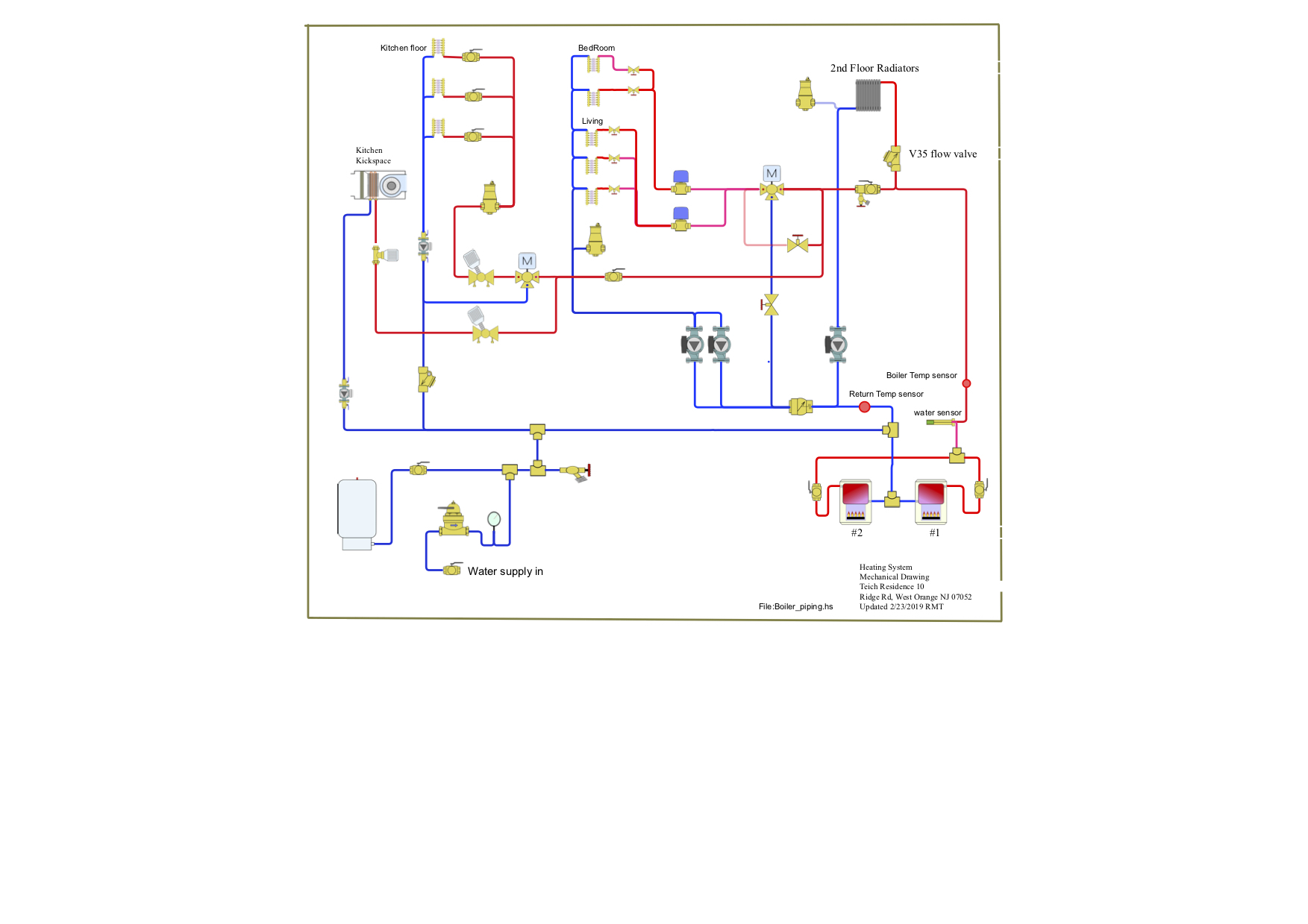
Since it was drawn, we moved the connection for the expansion tank to the top side of the reciculators on the main return (so that the recirculators pull water from the tank rather than push water in).
Thanks for any assistance and suggestions.
Comments
-
It's good that you moved the x-tank tie in. That was my first thought.
Air is being pulled in from somewhere. Have you tried closing all the Spirovent caps once the system is purged?8.33 lbs./gal. x 60 min./hr. x 20°ΔT = 10,000 BTU's/hour
Two btu per sq ft for degree difference for a slab0 -
There is no place on any "blue" line that the expansion tank could connect to assure all circulators pump away? Why are there 2 circs next to one another? They would both need checks to prevent crossing over to one another, if for some reason you need two in parallel?
On your 3 way valves, which is the mixed port?Bob "hot rod" Rohr
trainer for Caleffi NA
Living the hydronic dream 1
1 -
I agree with @Alan (California Radiant) Forbes & @hot_rod I looked at the drawing before I saw the note about the expansion tank.
As @hot_rod mentioned there is no common return pipe that the expansion tank could be piped to and the air eliminator should be on the hottest water...the boiler output.
The circulators need to "pump away" from the expansion tank. The resistance of your piping system if you are pumping toward the expansion tank shows up as a negative on your system and you could suck air in through an air vent. If you away the system resistance show up as discharge pressure
I don't know what the pressure setting of the relief valves on you boilers are but you might try raising the system pressure temporally to see if this helps1 -
Thanks HotRod for your comments. See modified drawing reflecting changes since 2019. You can see that we moved the expansion tank to a blue return close to the suction side of the pumps.
The two pumps were designed to meet the flow requirements of the system. They feed 2" supply feed and 2" return. I guess it was less expensive than using one larger pump. These are B&G 102214 ⅙ HP each.
The mix valve is the one marked with an M. 0
0 -
Thanks Ed for your comments. The pressure was raised to 22 PSI (no pump in action). Due to the height of the second floor, there is a pressure drop of about 10 PSI there, and sections of the return go through the floor of the second floor. When I do the daily purge to get the system to work, I make sure to stay above 15 PSI at all times.0
-
Thanks Alan for your suggestion to close the Spirovent cap and see if this helps. I have not done that. I guess I need to get suitable threaded caps.
The sprovent Vent2 can be isolated with a valve. I will try that one; I am already sceptical about its ability to vent air because it is a ½" copper welded vertically to a 2" curved horizontal steel pipe return as shown in the sketch above. The problem is that the 2" horizontal section disappears into a wall and ceiling. It starts to look like we will have to cut the plaster ceiling open for a stretch to see if we can add a full size Spirovent there. Headroom may be a problem.0 -
You still have a lone, upstairs circ that doesn't have a good reference to the expansion tank? that one will be toughest to get and keep air free.
A good microbubble air purger right at the boilers and some high point auto vents should work just fine. I would cap the air vent on the second floor rads as Alan mentioned, give it a try.
The large diameter piping is working against you for air, you want at least 2 feet per second velocity to carry air around to a central air purger. Vertical piping is tougher yet as air rises up even with downward flow if it is below 2 fps. So high point auto vents are going to be helpful. A float style vent will work best at high points, the spiros only work when flowing. The auto vents catch air when the system is off or running.
Parallel piping the boilers would eliminate the need for that solenoid.
Here is a really nice way to pipe multiple boilers, the sep gives you air, dirt magnetic and hydraulic separation. The expansion tank could mount at any of the four ports, assuring all circs are pumping away.
It would take some repiping to get this to a well balanced, hydraulically speaking, system.Bob "hot rod" Rohr
trainer for Caleffi NA
Living the hydronic dream0 -
Hi HotRod, The second floor heating system is trouble free. No air is getting in, and I test it for air in disbelief once a month...
Regarding your proposed multi-burner setup, where would the heating loops be attached?0 -
Here is some reading on how separators work and piping examples.dori said:Hi HotRod, The second floor heating system is trouble free. No air is getting in, and I test it for air in disbelief once a month...
Regarding your proposed multi-burner setup, where would the heating loops be attached?
https://www.caleffi.com/sites/default/files/coll_attach_file/idronics_15_na.pdfBob "hot rod" Rohr
trainer for Caleffi NA
Living the hydronic dream0 -
Thanks Alan for your suggestion to close the Spirovent cap and see if this helps. I have not done that. I guess I need to get suitable threaded caps.
The Spirovent comes with a cap and should be there unless someone removed it.
The two pumps were designed to meet the flow requirements of the system. They feed 2" supply feed and 2" return. I guess it was less expensive than using one larger pump. These are B&G 102214 ⅙ HP each.
I don't understand why these large volume pumps were used. Your max flow is probably around 11 GPM and one of those pumps (not 2) could easily do that with one hand behind it's back. See the 2" curve below.
8.33 lbs./gal. x 60 min./hr. x 20°ΔT = 10,000 BTU's/hour
Two btu per sq ft for degree difference for a slab0 -
Hi Alan, The max flow rate in 2" steel pipe is more like 45 gal/min than 11. The pumps go back to 1950 and the radiant load has not changed since. The system was commissioned and working at least until 1972. I am giving credit to the original designers -- they would not have been paid if it did not work properly, as this was a very upscale architect designed house.0
-
I think we understand each other. Your flow rate is around 11GPM - that's a guess - and I'm sure your system works fine. The smaller B & G Series 100 pump would have worked just as well and used less electricity. It's common to see a professionally designed system over pumped.
8.33 lbs./gal. x 60 min./hr. x 20°ΔT = 10,000 BTU's/hour
Two btu per sq ft for degree difference for a slab0 -
Question to Alan and anyone listening -- I need drawing software for the heating system. The one I used 2 years ago is buggy and there is no support. Any suggestions?0
-
I was using HydroSketch. As you rearrange some components, the legends get messed up, items you did not touch get entwined, and the MacOS version is even worse. My emails to the support went unanswered.0
-
HydroSketch is the one I usually recommend because it's so easy to use. I didn't know about the bugs. Other programs take more time to come up to speed and they're more for professional designers.
Please let us know what modifications you make to your system and if they resolve the problem. We are all here to learn.8.33 lbs./gal. x 60 min./hr. x 20°ΔT = 10,000 BTU's/hour
Two btu per sq ft for degree difference for a slab0 -
I met with Dori and went over this system. The home is spectacular and while I have no doubt it used to work beautifully, the system has been heavily modified by a forced air contractor who may have been in over his head. My immediate concerns are the pumping into a newly introduced 3-way mixing valve as opposed to drawing away from it, the lack of hydraulic separation between the system and boilers, and the placement of several venting devices, especially in relation to the pumps. @hot_rod My proposal will include a 2" Caleffi separator, the addition of 2 small boiler pumps, and a reconfiguring in the boiler room to include the necessary primary-secondary piping and control-programming principles.
To be clear, the system was designed without a mixing valve. There was an arrangement of tees and globe valves that allowed for blending of return water to the heating load and I guess some thermal protection for the single boiler was in place at that time. I believe the two pumps in parallel were meant for redundancy but Dori seems to think they've always both run in tandem. This mix of old and new isn't working well. It's an interesting project and I hope Dori and I can come to an agreement to regain the reliability of this piece of mechanical history. If so, I'm happy to keep you posted on our progress.
Best to all,
JohnContact John "JohnNY" Cataneo, NYC Master Plumber, Lic 1784
Consulting & Troubleshooting
Heating in NYC or NJ.
Classes
 3
3 -
Glad you found each other, you, Dori, and the system:)JohnNY said:I met with Dori and went over this system. The home is spectacular and while I have no doubt it used to work beautifully, the system has been heavily modified by a forced air contractor who may have been in over his head. My immediate concerns are the pumping into a newly introduced 3-way mixing valve as opposed to drawing away from it, the lack of hydraulic separation between the system and boilers, and the placement of several venting devices, especially in relation to the pumps. @hot_rod My proposal will include a 2" Caleffi separator, the addition of 2 small boiler pumps, and a reconfiguring in the boiler room to include the necessary primary-secondary piping and control-programming principles.
To be clear, the system was designed without a mixing valve. There was an arrangement of tees and globe valves that allowed for blending of return water to the heating load and I guess some thermal protection for the single boiler was in place at that time. I believe the two pumps in parallel were meant for redundancy but Dori seems to think they've always both run in tandem. This mix of old and new isn't working well. It's an interesting project and I hope Dori and I can come to an agreement to regain the reliability of this piece of mechanical history. If so, I'm happy to keep you posted on our progress.
Best to all,
John
Bob "hot rod" Rohr
trainer for Caleffi NA
Living the hydronic dream 3
3 -
Epilogue to the saga of the system locking up: JohnNY suggested that we open the mixing valve bypass to increase the flow. The system has worked well since then (after a few small purges).
Looking at 20 year old pictures taken before the upgrade that installed the Honeywell 1-½" mixing valve reveals that the old mechanically actuated valve and the piping to it were 2". Dah. Thanks John.0


Categories
- All Categories
- 87.7K THE MAIN WALL
- 3.3K A-C, Heat Pumps & Refrigeration
- 59 Biomass
- 430 Carbon Monoxide Awareness
- 127 Chimneys & Flues
- 2.2K Domestic Hot Water
- 5.9K Gas Heating
- 121 Geothermal
- 170 Indoor-Air Quality
- 3.8K Oil Heating
- 79 Pipe Deterioration
- 1K Plumbing
- 6.6K Radiant Heating
- 396 Solar
- 16K Strictly Steam
- 3.5K Thermostats and Controls
- 56 Water Quality
- 51 Industry Classes
- 51 Job Opportunities
- 17 Recall Announcements