Welcome! Here are the website rules, as well as some tips for using this forum.
Need to contact us? Visit https://heatinghelp.com/contact-us/.
Click here to Find a Contractor in your area.
If our community has helped you, please consider making a contribution to support this website. Thanks!
Old Monoflo tee pressure drop ratings and calculating system pressure drop
Options
Mike_Sheppard
Member Posts: 698
Does anyone happen to have info on pressure drop ratings on 2" and 2.5" threaded monoflo tees?
I am going to look at a one pipe hydronic system tomorrow. It is a split loop. Supply runs across the length of the building, splits to the front and rear, and runs back to the boiler room where they re-connect on the return.
I need to figure out how to calculate pressure drop on this system. Correct me if I am wrong: I need to calculate each branch as its own pressure drop. So I would need to add the resistance of the monoflo tee, the resistance of the branch piping, and the resistance of the heat emitter (convector), for each branch. And I would only do this for the longer of the two runs. In John Siegenthaler's book he calls each branch a subassembly.
I already know the pump is undersized just by doing the rule-of-thumb method. The system is getting a 25 degree delta T on a 50 degree day. The convertors are constantly getting air trapped in them. Flow velocity is too low to entrain air. There are several other issues as well. But I need to get the pump sized correctly.
Never stop learning.
0
Comments
-
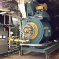
They have two 750,000 btu boilers. 1,500,000 total. System piping is 2.5 inch. System design is 20 delta T. That puts it at 150 gpm if the boilers were sized properly. Which is 10fps through a 2.5 inch steel pipe. That tells me the boilers are oversized. So they've got oversized boilers, with an undersized pump.Never stop learning.0
-
I would think calculate the one branch of radiation with the highest pressure drop + the split the loop with the highest pressure drop + the resistance of the boiler and the common piping and components.
Also have you sized the radiation? Could be that they have 2 boilers with 100% redundancy. In that case the piping and pump would only need to support 750,000. How old is the job? All original? If it's monoflow it is probably 1950s-1960s. They usually sized the pipe right on those old jobs. Unless it's been MIckey Moused0 -
I was thinking each branch of radiation is kind of like a single fitting in the line. At least that’s how John Siegenthaler’s book describes it.
I’m sure it’s closer to 100% redundancy than anything. They’re also piped primary/secondary incorrectly and are being run at condensing temperatures off of a reset controller, but that’s a whole different problem.
I have no idea where to start with calculating pressure drop through the monoflo tees. There is absolutely zero literature I can find on them. I don’t even know what a good estimate would be. I do know the standard rule-of-thumb method won’t work with a monoflo system. I have no clue how to calculate this.
Maybe I can add gauges somewhere at the pump to see the current GPM the pump is moving. 2.5 inch pipe at 4fps is 60gpm. That would mean one single 750,000btu boiler at 80% efficiency would match 60gpm exactly. Now it definitely sounds like one is redundant. I know for sure it’s not moving that much currently. Maybe someone at B&G would be able to guesstimate which pump I could put in to make up the difference.Never stop learning.0 -
If the system is running -- or can be run -- now, by far the easiest way to do your calculation is not to even try. What you are interested in is the pressure drop/flow relationship in the entire loop, right? And once you get that for any flow rate, you can replace -- mathematically -- the whole thing with a single piece of pipe which has the same pressure drop at the same flow, and go from there.
So... put a pressure gauge at one end of the loop, and another at the other, and fire up a pump which you can get the flow rate on (there are ways to do that, too -- for instance, if those two pressure gauges happen to be at the pump inlet and outlet, and you have or can find the pump performance curve, just match the pressure added by the pump to the pump curve and there's your flow) and off you go.
Computing the flow and pressure drops through a system with multiple branches and fittings -- even normal fittings -- is messy. It can be done, of course -- I used to do it all the time -- but there are quicker slicker ways to do it.Br. Jamie, osb
Building superintendent/caretaker, 7200 sq. ft. historic house museum with dependencies in New England0 -
@Mike_Sheppard
If they are B&G monoflows or Taco I am sure you can get PD info from them. I used to have a book "Taco Guide for Hydronics" I have it somewhere will look. Also the old B & G handbooks had that info I think. There may be one on this site you can look at. I will look through my stuff this weekend.0 -
Got the system back up and running. Was completely air locked. They had guys out trying to bleed air from one single convector on the top floor. I bled air from the top of the air separator with a hose for a solid hour. Then spent the next few hours bleeding air from 75 convectors.Never stop learning.0
-
Calculating flow resistance of parelled branches....... assuming they are different, I'ld calculate resistance of each branch separately ( pipes, monoflows, emitters....) , then calculate equivalent resistance of the 2 branches in parallel ( if you want to be engineering accurate). Resistance in units of .......(pressure drop)/( flow rate). Then add in resistance of rest of the system.
For paralleled loops.....Should be similar math to finding equivalent resistance of 2 paralleled electrical resistors, 1/Requivalent = 1/R1+1/R2 ( been years since I calculated fluid flow).
( if you parallel 2 identical pipes, then flow resistance should go down by 1/2)
------------------------
With air in the system wonder if you have a leak somewhere.0 -
Made a little bit of progress. Managed to get my hands on the pressure drop charts for the old monoflo fittings. I still don’t know if this is for the branch plugged or not. And I’m not sure how to calculate the pressure drop for the fitting with the heat emitter branch.Never stop learning.0
-


Categories
- All Categories
- 87.6K THE MAIN WALL
- 3.3K A-C, Heat Pumps & Refrigeration
- 59 Biomass
- 430 Carbon Monoxide Awareness
- 124 Chimneys & Flues
- 2.2K Domestic Hot Water
- 5.9K Gas Heating
- 120 Geothermal
- 168 Indoor-Air Quality
- 3.8K Oil Heating
- 78 Pipe Deterioration
- 1K Plumbing
- 6.6K Radiant Heating
- 394 Solar
- 16K Strictly Steam
- 3.5K Thermostats and Controls
- 56 Water Quality
- 51 Industry Classes
- 50 Job Opportunities
- 18 Recall Announcements