Welcome! Here are the website rules, as well as some tips for using this forum.
Need to contact us? Visit https://heatinghelp.com/contact-us/.
Click here to Find a Contractor in your area.
If our community has helped you, please consider making a contribution to support this website. Thanks!
Adding Zone Valves to Weil McClain HE Boiler
Options

Mudaero
Member Posts: 46
Hey all,
I want to add 2 zone valves (Honeywell V8043E) to an older Weil McClain HE boiler. Currently, I only have one thermostat connected directly to the boiler as shown in the image below...

The wiring schematic for the boiler is this...

And this is one of the wiring diagrams from Honeywell that seemed to match what I am trying to do (eliminating the third zone valve and thermostat)...
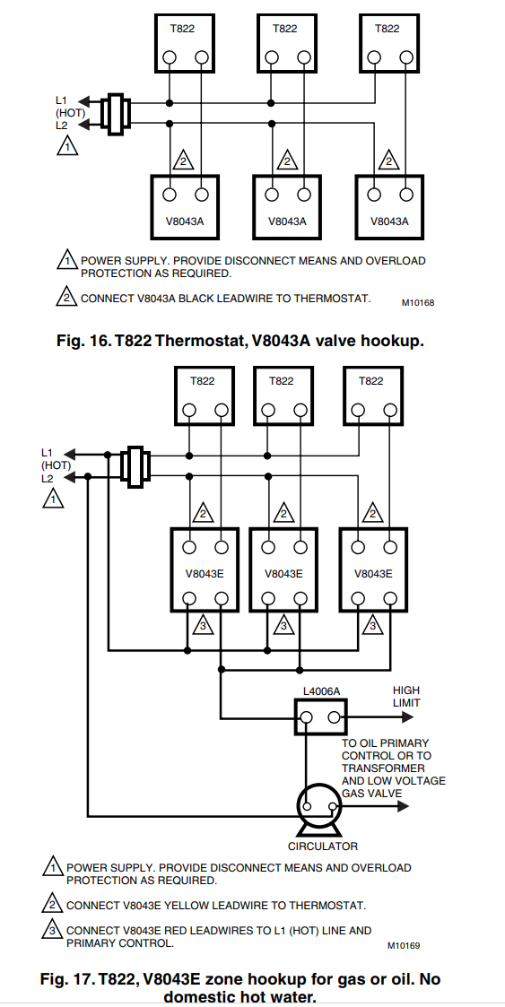
I want to use the V8043e valve because I can get it as an NPT body instead of sweat. But looking at the diagram, it seems like the v8043a would be the one I should use. Can any one help me wire the v8043e to my system or give me any advice on how I should proceed? Please let me know if there is anything else I can describe or any information needed. Thanks for looking. I appreciate any help.
I want to add 2 zone valves (Honeywell V8043E) to an older Weil McClain HE boiler. Currently, I only have one thermostat connected directly to the boiler as shown in the image below...
The wiring schematic for the boiler is this...
And this is one of the wiring diagrams from Honeywell that seemed to match what I am trying to do (eliminating the third zone valve and thermostat)...
I want to use the V8043e valve because I can get it as an NPT body instead of sweat. But looking at the diagram, it seems like the v8043a would be the one I should use. Can any one help me wire the v8043e to my system or give me any advice on how I should proceed? Please let me know if there is anything else I can describe or any information needed. Thanks for looking. I appreciate any help.
0
Comments
-
Figure 16 doesnt show an end switch, which is needed.
Figure 17 looks like line voltage switching which you can't use with the factory wiring.
You need 2- 24v zone valves with end switches.
The black wires that the existing thermostat wires are spliced to are the wires you connect to the zone valves end switches, in parallel.
Instructions will come with the valves.
That is a 40va factory transformer so 2 zone valves is fine.
Checked all other hydronic parts before you drain the boiler. Time for a new air eliminator, PRV, relief valve, etc? 1
1 -
Ok, I think that makes sense. I have already changed out the other parts when I made my initial changes to my system last year. I will look for some other zone valves and will most likely come back on this thread to make sure that it will be what I need. Thanks for the help, it is appreciated.0
-
Hey HVACNut,
Would my wiring diagram look something like this below? I realize the control unit might not be the same as mine, but I'm using this image as a generalization. If so, I guess my confusion lies at where the lines from the transformer go to the thermostats, since those appear to be the ones I'm tying the reds to from the zone valve. Do I need to pull new leads from the transformer to go to the thermostats or do I just split off the ones that are there? I also included the wiring diagram for a White Rodgers system as shown in the zone valve instructions since that's what's on my boiler. Again, thanks for your input. I apologize for my ignorance on the subject, but I'm trying to learn everything I can.

0 -
Or do I simply need a new transformer and then wire like the top diagram and have the two reds going into the boiler and connecting to the two black leads?0
-
A zone relay board would simplify all this and prevent mis-wiring.
You get a fused transformer, indicator and trouble shooting lights. Caleffi and others now have 3 wire connection for power stealing or digital thermostats. A single 2 wire to call the boiler on.Bob "hot rod" Rohr
trainer for Caleffi NA
Living the hydronic dream
 2
2 -
Thank you for the advice. While I would like to use a relay board, it's just not feasible right now. When I replace my boiler, I will do that, but for this current project, I just want to use what I have.0
-
What size is the transformer in the boiler you are connecting to?What is the amp draw of the boiler controls? You need to make sure the transformer has capacity.
Just by one of these and follow the simple diagram and you won't have to worry about any of that. You can leave it in place when you install the new boiler.
https://www.supplyhouse.com/Taco-ZVC403-4-3-Zone-Valve-Control-Module-with-Priority"If you can't explain it simply, you don't understand it well enough"
Albert Einstein0 -
It can be wired exactly like the top diagram.
You dont need a new transformer. The boiler has a typical HVAC fan center control with a 40va transformer.
Using the top diagram,
At the 24v side of the transformer, we'll use the top black wire as power. That is designated 'R' on the transformer.
The bottom yellow wire coming out of the transformer we'll designate as common. 'C' on the transformer.
It wouldn't be a bad idea to install an inline fuse. 5A.1 -
Excellent! That completely clarifies everything for me. I really appreciate your help on this matter. I can't thank you enough.0
-
Hey HVACNut,
Just wanted to let you know that everything is working brilliantly. Hookup was simple and your help with the wiring was crucial. Just wanted to thank you again for your assistance. -1
-1

Categories
- All Categories
- 87.6K THE MAIN WALL
- 3.3K A-C, Heat Pumps & Refrigeration
- 59 Biomass
- 429 Carbon Monoxide Awareness
- 124 Chimneys & Flues
- 2.2K Domestic Hot Water
- 5.9K Gas Heating
- 119 Geothermal
- 168 Indoor-Air Quality
- 3.8K Oil Heating
- 78 Pipe Deterioration
- 1K Plumbing
- 6.6K Radiant Heating
- 394 Solar
- 16K Strictly Steam
- 3.5K Thermostats and Controls
- 56 Water Quality
- 51 Industry Classes
- 50 Job Opportunities
- 18 Recall Announcements