Welcome! Here are the website rules, as well as some tips for using this forum.
Need to contact us? Visit https://heatinghelp.com/contact-us/.
Click here to Find a Contractor in your area.
If our community has helped you, please consider making a contribution to support this website. Thanks!
Need help - one pipe monoflo system
Options
Mike_Sheppard
Member Posts: 698
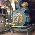
I am a commercial service technician and I got this call yesterday. It was a One-pipe, split loop system. I will attach a picture of the system layout. The problem was, the below-main convectors were not getting hot. The above-main ones were getting hot. They had a tech there for 3-weeks "bleeding air" trying to get the convectors hot. ("If you aren't getting air, it ain't an air problem, stupid!").
So what I found was, in the 2-1/2 inch main, leaving the pump, a contractor had added an in-line floor mounted filter. They cut the main, and piped down to the floor into a smaller 2" in-line filter with a 20 micron filter in it. As soon as I saw that I figured it was a flow issue. The customer told me that it was installed 3 weeks ago and the below-main convectors hadn't heated since. Luckily, they left a full size 2-1/2 inch bypass around this filter. I opened the bypass and almost instantly the below-main convectors started heating with 160 degree water. So that solved that issue. But there were some other issues that I noticed and I documented everything and wanted to bring it here to see what more experienced guys think. I have read a lot of books that talk about these systems from guys like Dan and Ray Wohlfarth, but this is the first one pipe system I've encountered in the field in 11 years.
In the attached picture, I did not draw in the convectors. The below-main convectors have a monoflo tee on both the return and supply, and the above-main have them on the return. Below main convectors are 3/4 inch piping, first floor is 1/2 inch piping, and second floor is 3/4 inch piping.
So my concerns about the system are the following:
1. The random abandoned monoflo tee in the return line that is plugged off. I can only assume maybe the boiler room had a convector in it to help keep it warm during the winter.
2. The main goes out as 2-1/2 inch, splits to 2 inch, and comes back, but does not go back to 2-1/2 inch, it stays 2 inch after combining. The boilers are not original. They were piped in with copper, and the main loop piping they attach to was dropped down to 2 inch copper as well. The manifolds for the primary/secondary are also 2 inch.
My questions are:
1. Is the circulator capable of pumping the GPM this system needs? I used both Dan's and Ray's method of estimating system friction loss, and I came up with 19.5 ft/head with both methods. If I am looking at the correct pump curve for this pump, 19.5 ft/head is outside of the range of this pump curve. But the pump is circulating water and the main has a 20 degree delta T across it while running. I'm not sure what I am missing here.
2. Does the abandoned monoflo tee serve a purpose, or does it need to be removed?
3. Should the main rejoin as 2-1/2 inch? Should the main piping where the boilers are be 2-1/2 inch? Shouldn't the primary/secondary manifolds for the boilers be 2-1/2 inch? If each boiler needs 30.5 gpm for a 20 degree rise, the main and the manifolds would see 61 gpm. For proper velocity, should pipe size for 61 gpm be 2-1/2 inch?
4. Should the balancing valves at the ends of the loops be set to maintain a 20 degree delta through each loop? They are both currently wide open and seized that way. I'm wondering if they were left wide open because of an undersized circulator/piping/abandoned monoflo tee. The longer loop is seeing a 25 degree delta T and the shorter loop is seeing a 15 degree delta T.
This is my first one pipe diverter tee system encounter, so I wanted to ask these questions here and hopefully get some feedback from much more experienced people with this system. Thank you to anyone who takes the time to let me know if I am on the right track here. Any feedback is greatly appreciated!
Never stop learning.
0
Comments
-
Ok. You cannot have an abandoned diverter/monoflow tee. It will definitely mess up the flow. And the return piping seems fine to me. My house has a 1-1/4 supply main and two 1" returns. The placement of the monoflow tees seem fine, I've been reading about this a lot lately.
.
I don't think the filter is going to work. Diverter tees need proper flow to function.0 -
You could add another 2" strainer/filter in parallel and get the flow rate back? If that restriction was the only thing preventing the system from working perhaps I would not worry about the reduced return of 2".
It seems the strainer(s) would be better utilized if placed ahead of pumps and boilers.
0 -
If everything is heating now, and customer is happy, then what is there to resolve? Or is this for future troubleshooting?
Cutting out the tee will decrease restriction and delta t. Why did the installer add the strainer? Did a pump get killed by debris?0 -
Is it possible that that tee is supposed to be there, to purposely decrease flow? Is there any evidence of it ever being connected to anything?0
-
There is a delicate balance to that type of system, adding that additional strainer would add a few ft of head to the circuit. Even a brand new, clean Y strainer has a bit of pressure drop.
Different opinions on abandoning take offs. B&G suggests connecting removed rads with straight section of pipe to keep the balance. Others here have added TRVs and removed rads without a problem.
They can be a bugger to purge, especially branches down below the main. It may take a high flow purge pump to blast it clean, A 1/2 fill valve may not provide adequate volume to get a clean purge.
B&G still has some of the best info on these systems design and trouble shooting. You can get to some info on their site, you may need to register to get into the deeper training topics.
You'll notice some of the writing over at B&G looks vaguely familiar") Dan has a long reach into this industry. Bob "hot rod" Rohr
Dan has a long reach into this industry. Bob "hot rod" Rohr
trainer for Caleffi NA
Living the hydronic dream 1
1 -
Engineer not heat tech , but 20 micron filter is pretty fine, sounds too fine for this application. We used 2 micron to remove bacteria from water in a medical company.
Sounds like they were trying to remove brown water, (fine rust partials maybe, overkill).
Might try blowing thru the filter , it might have done it's job and got plugged from partials. If so cut it open and see what it's caught. Might be some other garbage in the system
Abandoned monoflow tee will act as a restrictor or orifice, causing head losses, (so lower flow rate). Likely more so than elbows and tees since internal cross sectional area is reduced..0 -
The below-main convectors wouldn’t heat even with the filter insert removed. Just dropping the main down to 2” was enough to cause the issue.
But the system is back to working. They have heat. I was just hoping to get some feedback on my calculations on the system. Kind of using the example I posted about as a way of trying to learn more.Never stop learning.0 -
@Mike_Sheppard 61 gpm should have 2 1/2" pipe. 2" runs out of gas at about 40-45 gpm. 50 would be pushing it.
It is best if unused monoflo tees are removed. When flow hits a monoflow tee it goes in 2 directions so lets say your 61 gpm hits a monoflow tee (that has a branch connected) say 50 goes straight through and 11 goes up the branch. Now you plug the branch and force all 61 through the monoflow, it will likely go but will increase the pump head due to the restriction. Too much of this will force the pump out of it's curve and you get reduced flow.
Calculating pump head is not difficult but charts for fittings I find vary widely with varying estimates for fittings. You usually end up with less actual head than calculated-1 -
Likely a safety factor built into the calculation tables, that's why actual head is less.
Internal surface roughness is a factor in calculating friction loss , at least for straight pipes. So different assumed roughness could trickle down to different equivalent feet tables for fittings.
-1 -
What I am thinking is, maybe that "ballpark" equation doesn't work in this situation because of the way this system is. Since the pipe splits into two loops, which are almost indentical lengths but are smaller pipe, I don't think just measuring the longest loop is going to give an accurate answer. The main goes out as 2.5 inch, and splits to two 2 inch loops that are almost the same length. Two 2 inch pipes add up to a larger cross sectional area than a single 2.5 inch pipe. Meaning they would offer less resistance to flow. Which would reduce the head of the system.
I'm thinking that the correct way to calculate this particular system is outside of my realm of knowledge at this point. Perhaps I can take this example to the Carrier hydronic system engineering class I am going to this year. If anyone is interested in the stuff I HIGHLY recommend Carriers engineering classes taught by Will Wyman. The man is a wealth of engineering knowledge.
I think if this pump had suction and discharge gauges it would be much easier to tell if it was sized properly or not.Never stop learning.0 -
You have to calculate the head on that portion of the system that has 2 1/2" pipe with a flow of 61 gpm and get those #s .and the total feet of head for that
Then you calculate each of the 2" loops separately and find the head for each of those. But you need to know the flow through each 2" loop. Assuming they are equal use 30 gpm each for both of those loops .Then you take the head from the 2" loop that has the highest head (and forget about the other loop) and add it to the head for the 2 1/2" loop. That's your total head.
Add in the boiler head loss, air separator etc and any other components to the 2 1/2" section.
Many people take the resistance found for the pipe length and multiply x 1.5 to allow for fittings. To inaccurate for me. I count each and every fitting and component and calculate accordingly. Takes a little work but I have never undersized or had a job not work and I have fixed plenty of jobs that were done wrong.
Download the B & G system sizer app and have at it. It's not that hard. Nothing wrong with Carrier training but you can figure it out without them-1 -
Just from a theory point of view, for equivalent head loss of parelled section would guess you'ld calculate the flow resistance separately on each of the 2 parelled loops alone. Then calculate the parelled combination. I forget the details but would think it's similar to calculating the equivalent resistance of 2 electrical resistors parelled.
For electrical resistor 3ohm in parelle with 4 ohms resistor the equivalent resistance is ( 1/R-equivalent) = 1/3 +1/4
So R -equivalent = 1.7 ohms
Would guess if you express flow resistance as (head loss/GPM) might be able to use the electrical resistance equivalent method above. (assumes flow is laminar not turbulent, so linear flow resistance, not porportional to square of GPM ).-1 -
Makes sense. Thank you guys a ton for the info. I knew I wasn’t looking at it correctly. I spent some time searching through my B&G design manuals and actually found an entire section on “series loop two circuit” systems. This will help a ton.
So let’s say we have a 100ft run of 2.5 inch black pipe. According to the System Sizer that would be 2.71 feet of friction loss.
Now let’s say in the middle of that 100 feet of 2.5 inch pipe, 10 feet of it is cut out and replaced with 2 inch pipe. So now there is 2.4 feet of loss on the 2.5 inch pipe and 0.657 feet of loss on the 2 inch pipe. Adding together to get 3.057 feet of loss total.
So now I’m thinking in my original example, dropping to 2” for only a couple of feet to add in the filter wouldn’t be a problem, but the filter itself was likely the problem.Never stop learning.0 -
Would you guys happen to have any old flow loss data for 2 inch threaded monoflow fittings?Never stop learning.0
-
And old B& G manual may have this. I have one somewhere. I will look.
-1


Categories
- All Categories
- 87.6K THE MAIN WALL
- 3.3K A-C, Heat Pumps & Refrigeration
- 59 Biomass
- 430 Carbon Monoxide Awareness
- 124 Chimneys & Flues
- 2.2K Domestic Hot Water
- 5.9K Gas Heating
- 120 Geothermal
- 168 Indoor-Air Quality
- 3.8K Oil Heating
- 78 Pipe Deterioration
- 1K Plumbing
- 6.6K Radiant Heating
- 396 Solar
- 16K Strictly Steam
- 3.5K Thermostats and Controls
- 56 Water Quality
- 51 Industry Classes
- 51 Job Opportunities
- 18 Recall Announcements