Wiring 120v LWC on Millivolt system

I want to add a low water cut off to my millivolt system. Instead of getting a Mcdonnell Miller 67 lwc and #11 switch could I wire the 120v RB-122-E to interrupt power to the Aquastat thereby avoiding 120v to my millivolt gas valve and having to buy a 67 lwc and #11 switch. I would wire it like this:
Comments
-
It appears that model has a set of isolated contacts, you should be fine wiring it in per option 2 of the manual (here), and breaking the millivolt signal directly with the yellow wires/terminals B & C.
[edited to add] You will still need to feed the LWCO with 120 volt (from a convenient supply), but you may not have additional controls as shown in the diagram
0 -
wait what..N C? Ratio said B and C. B and C are dry contacts that can be directly wired to the millivolt valve? or actually I mean I should wire in aquastat B1 to Lwc B, to gas valve hot and aquastat B2 to lwc C, to gas valve neutral?

0 -
We need all the information on your boiler and controls to provide the correct answer
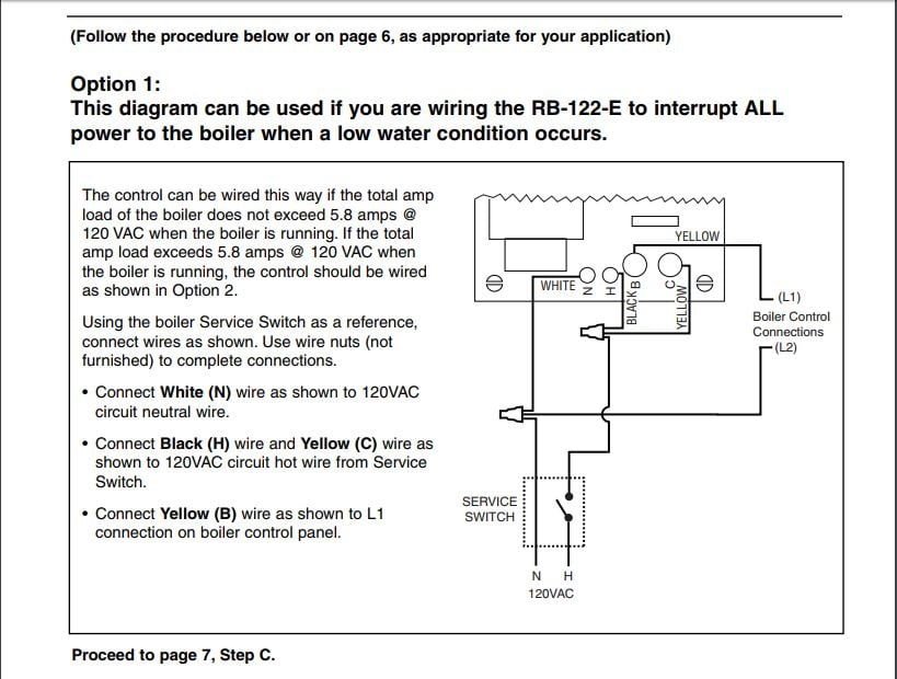
Wire terminal N on the LWCO to terminal L2 on aquastat
Wire Terminal H "" "" "" L1 " "
Do not install a jumper between terminals H & B on the LWCO
Remove the wire between B1 on the aquastat to TH1 on the gas valve.
Wire from Terminal TH1 on the gas valve to terminal B on LWCO
Wire from Terminal B1 on aquastat to Terminal C on LWCO
Check operation of LWCO and all safety controls after completion
0 -
> @HydroNiCK said:
> wait what..N C? Ratio said B and C. B and C are dry contacts that can be directly wired to the millivolt valve? or actually I mean I should wire in aquastat B1 to Lwc B, to gas valve hot and aquastat B2 to lwc C, to gas valve neutral?
N.C. meaning Normally Closed.0 -
That particular LWCO you mentioned needs to be powered from 120 volt, regardless of any other power/control voltages. Also, that particular one provides an isolated normally-closed (opens on fault) contact. That must be used to shut down the burner itself, usually by interrupting the control signal, but just as easily the main power for the burner. With a millivolt system, they're one and the same.1
-
The control signal and millivolt power are not one and the same. Yes the thermopile generates power but the control signal comes from BB. Wiring the gas valve to lwc BC maintains a closed circuit because the dry contacts are pulled in but open when there is a fault in line voltage. Aside from that what tells the burner to fire? The only thing to do is bring aquastat's BB into the circuit . When the low water cut off's BC gets forced away and opens it breaks the circuit and prevents the burner from firing by breaking the signal to fire.0
-
AreN't we all saying the same thing...0
-
Possibly. How 'bout a pic of the gas valve, maybe a model number? I'm not understanding what exactly you've got there. If it's a millivolt system, you don't need external power (120 or 24 volt) to operate it. If it's a powered gas valve you don't need a millivolt generator. (I think we have a nomenclature issue.)
In any case, breaking the control signal should shut it down properly, and as the contacts are isolated we don't really care what the voltage is anyway, other than the wiring method must meet the appropriate Code. A quick check is to cut/disconnect one of the wires while the burner is firing, if the burner goes out then we're fine.
0 -
Do you have a steam boiler?
0 -
How are you interrupting the control signal of burner by wiring it to those dry contacts? If the burner is only wired to that dry contact what is telling it when to fire? If the dry contact is normally closed then opens what difference would it make since no control was in that circuit anyway telling it to fire? I have hot water boiler. The only thing that can be cut is line voltage powering the aquastat. As in wiring diagram 1. The 2nd diagram is wired assuming the burner is powered from a source that can be cut out. With mv gas valve the signal to fire has to be interupted. With 24volt valve the power to it is interupted. No? Am I wrong?0
-
Ok. You wire the LWCO 115v to H & N.
On the aquastat, leave B2 to TH2 on the gas valve alone.
From B1 on the aquastat, run a wire to B on the LWCO. Then from C on the LWCO to TH1 on the gas valve.
If there is a low water condition, the circuit from B1 to TH1 will open, shutting down the gas valve.1 -
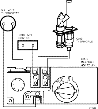
The wire need to be interrupted by the contacts in the LWCO. Here is a simplified schematic of a millivolt gas valve. What's called the "millivolt thermostat" represents your aquastat, "high limit control" your new LWCO. The terminal on the gas valve with two wires on it is merely a splice point.
I'm still not positive you have a millivolt gas valve. With a millivolt valve, the power to operate the valve comes from the millivolt generator, as long as the pilot light stays lit the valve has control power. If you're sending power to the gas valve, either 120 volt or 24 volt, it can't be a millivolt valve.
A few pics or a model number or something would help immensely. I'd be able to figure out what part of what I'm thinking isn't matching up with what you're seeing.
0 -


0 -
Ahh, memories0
-
Great, thank you.
It is a millivolt gas valve. The aquastat has a set of dry contacts (B1/B2) that control the gas valve. You need to be in series with that contact. Remove one of the wires from B1 or B2 (doesn't matter which) & extend it to B or C (doesn't matter which) in the LWCO. From the other contact in the LWCO extend a wire to the terminal you removed the wire from. Either contact will shut down the burner.
1 -
You made it this far with out a LWCO why bother now. The new boiler will have one.1
-
Yeah I know right.. I recently moved into this house. That 80k btu dinosaur only heats 64ft baseboard in my mother in laws apt on 2nd floor. I am tying in a radiant floor to that boiler. Since i'm re-piping and the boiler will be off I thought about adding LWC to it since the radiant is over a garage and if it freezes and bursts the boiler will shut down. I never worked on a millivolt system before. Since i'm a piper and not much of an electrifier..i'm lacking in the controls department. I'm going to get a new boiler in a couple of months anyway but this is what I got to work with for now. After a certain point in this discussion I lost interest in actually installing it but gained a lot more interest in trying to understand the wiring. Thanks Ratio and HvacNut for your help. It's funny how i just looked at the link Ratio posted and it makes sense what he was saying yet after seeing my pic I think it made sense what I was saying. I guess a picture is worth a thousand words0


Categories
- All Categories
- 87.4K THE MAIN WALL
- 3.3K A-C, Heat Pumps & Refrigeration
- 61 Biomass
- 430 Carbon Monoxide Awareness
- 120 Chimneys & Flues
- 2.1K Domestic Hot Water
- 5.8K Gas Heating
- 115 Geothermal
- 168 Indoor-Air Quality
- 3.7K Oil Heating
- 77 Pipe Deterioration
- 1K Plumbing
- 6.5K Radiant Heating
- 395 Solar
- 15.7K Strictly Steam
- 3.4K Thermostats and Controls
- 56 Water Quality
- 51 Industry Classes
- 50 Job Opportunities
- 18 Recall Announcements