Pumping Away Piping

Consider this piping arrangement using the Pumping Away method.


Comments
-
How can I apply this air bleeding technique to a primary secondary piping set up ?

 1
1 -
It's true! I've said it before and I'll say it again here: ever since I've been doing my installs "pumping away" commissioning is so simple. After power purging each zone: Turn on boiler, run zones, get heat, clean up, done.Serving Northern Maine HVAC & Controls. I burn wood, it smells good!2
-
Absolutely true. Dan literally "wrote the book".
I would point out that air eliminators also make pretty good dirt eliminators. I have noticed especially in older systems, that when the expansion tank is directly below the air eliminator, the tanks get debris in them. It is not a bad idea to put a Tee directly below the eliminator and pipe the expansion tank from the side of the tee. You can then install a valve to blow the debris on the bottom of the Tee. Probably not needed on every job, just something to think about."If you can't explain it simply, you don't understand it well enough"
Albert Einstein

 4
4 -
Do you guys put a shutoff on each return line or leave them out like the diagram? I have done this setup since reading on still stick with the return line shut offs.
Here's a pic of the most compact version I've installed.
0 -
Is that 1 zone, split loops? If so then what you've got there is the only way you can do it.
I still like to put a ball valve on my return manifold. I have stock in brass.0 -
Just like the picture from pumping away with zone valves. You see the 4 return lines in the picture.0
-
I have been using this method ever since seeing it in the book, and love it. It is the best way to make sure all air is out, without any air pockets left behind. I also do put valves on my returns just so I can isolate them if I need to.
Rick
0 -
Hilly: That's awesome.
Yes, Mr. Dan has made my professional life a whole lot easier when I learned to install his purge assembly. Brilliant!8.33 lbs./gal. x 60 min./hr. x 20°ΔT = 10,000 BTU's/hour
Two btu per sq ft for degree difference for a slab0 -
Pumping away from an Xtank is good. Pumping away from an air eliminator, I don't know. There is a possibility of pulling air into the system. I like pumping into an air separator on the supply side (hottest water).0
-
the confusion I hear over and over has to do with the need to pump into the new high efficient, high pressure drop boilers, and where to locate the expansion tank connection.
The air sep performs best at the boiler supply, the hottest point in the system.
But the expansion tank does not need to be on, or be able to be on the air sep, it needs to be near the inlet of the circulator(s)
So if the circulator is at, or in the boiler, pumping the return side, choosing the correct expansion tank connection becomes a bit more confusing.
With a multiple circulator P/S piping... now where?Bob "hot rod" Rohr
trainer for Caleffi NA
Living the hydronic dream2 -
Agree w/confusion. With the secondary circs pumping away from the primary circuit does not this become the PONPC? In the supplied illustration, Would it be ok to place expansion tank below the air eliminator on a tee and supply make up water to a tee above the expansion tank as shown in numerous boiler diagrams?
0 -
The circuit that the expansion tank is connected into, becomes the primary circuit.
Moving the tank to the air sep in the above drawing, makes the boiler loop, or circuit, the primary loop.
That is the opinion of Gil Carlson as relayed by Dan in his primary secondary teachings.
Bob "hot rod" Rohr
trainer for Caleffi NA
Living the hydronic dream0 -
question then. Would it make any difference if we put the expansion tank on the supplu side ( outlet) of the boiler or the return side ( inlet to boiler circulator) as shown in drawing? Would one design be better then the other? Thanks
0 -
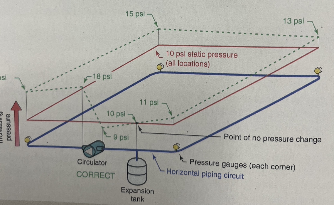
You want the circulator to be pumping away from the expansion tank connection.
These two drawings show how the circulator adds its ∆P, pressure differential, to the system when pumping away from the tank connection, the PONPC point of no pressure change
The red loop shows the static fill pressure of 10psi. The blue loop is the dynamic pressure conditrion, the circulator running.
 Bob "hot rod" Rohr
trainer for Caleffi NA
Living the hydronic dream0 -
Great diagram! thanks for the explanation. can see benefit of installation on the suction side of circ on return side of boiler inlet in primary loop. Appreciate the lesson!
0 -
Awesome! This raises one very important question for me... just one! In pumping away from the expansion tank and it creating the point of no pressure change... is there a specific distance, or rough distance, that the expansion tank has to be ahead of the circulator(s)? Or could it be 15", 5', or 10'... due to the fact that that the expansion tank always has system pressure on it (providing the bladder pressure equals system pressure - below 70/80 psig), thereby creating that equilibrium with minimal water movement?
0 -
Correct, the tank connection establishes the PONPC. So any distance between that point and the circ inlet has a small amount of pressure drop. How much? It depends on pipe size, flow rates, type of fluid.
I suppose you could put some numbers to that small pressure drop, if you had all the data. I would suggest as close as possible. A few to 5' would not be a deal breaker.
One goal is to have all the circ ∆P pressure differential added to the circuit.
An example of the small "droop" here.
What you want to avoid is pulling a sub-atmospheric condition, negative pressure in the circuit. Under that condition, air could be pulled into an auto air vent, for example.
l

The circulator pumps want some positive pressure at the inlet. Grundfos shows anywhere from 1.3- 4 psi at 140- 190° water temperature. The hotter the water the more prone to cavitation without adequate NPSHr net positive suction head required
 Bob "hot rod" Rohr
trainer for Caleffi NA
Living the hydronic dream 1
1


Categories
- All Categories
- 87.7K THE MAIN WALL
- 3.3K A-C, Heat Pumps & Refrigeration
- 59 Biomass
- 430 Carbon Monoxide Awareness
- 129 Chimneys & Flues
- 2.2K Domestic Hot Water
- 5.9K Gas Heating
- 122 Geothermal
- 170 Indoor-Air Quality
- 3.8K Oil Heating
- 79 Pipe Deterioration
- 1.1K Plumbing
- 6.6K Radiant Heating
- 396 Solar
- 16K Strictly Steam
- 3.5K Thermostats and Controls
- 56 Water Quality
- 51 Industry Classes
- 51 Job Opportunities
- 17 Recall Announcements