2 Thermostat- 2 zone valve wiring

Can anybody tell me where that should connect. Thanks, Forrest
Comments
-
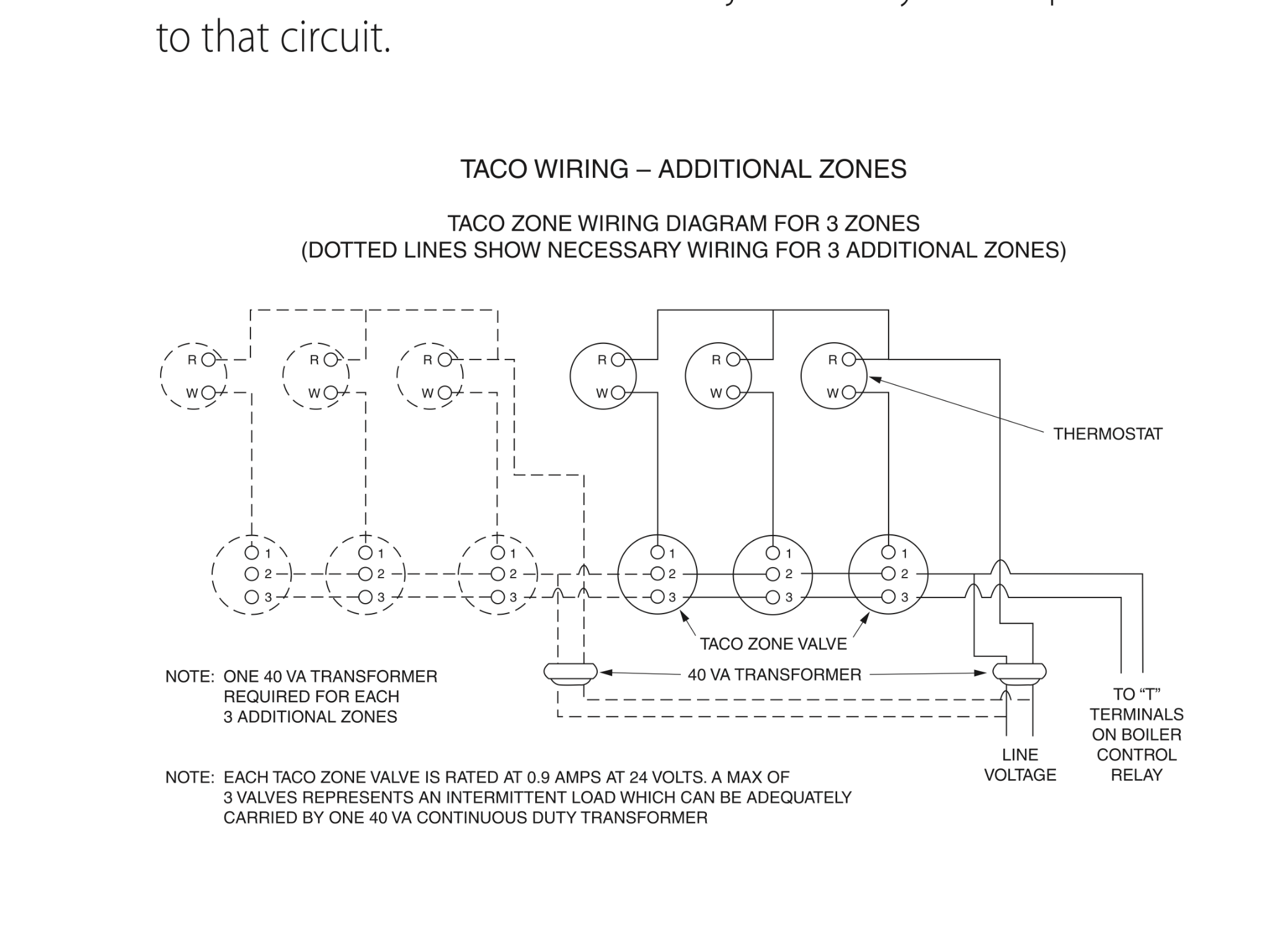
Forest - Got a little dizzy looking at your schematic : ). Take a look at this. Disregard the dotted lines and everything connected to them.
Steve Minnich
 1
1 -
Picture below has electrical box with transformer on it that has 2 connections. Is there a positive and negative here? I read 29 volts across it.
Under this 2 wires stick out (I'm going to guess these go to "T" terminals on boiler) see pic
++++++++
So the red wires from the 2 thermostats go to the transformer, which post?
Sorry, I'm dizzy
0 -
If you want the positive terminal, it is the brass screw. If your side note is correct, the white wire should be on terminal #3 on the Taco head and red on #20
-
I tried to simplify the illustration. You can see thermostat 2 green connection is not connected to anything.
bill: would you say the brass is on the left in the photo? If so what leads go to it?
Those 2 wires that I am assuming go thru the conduit to the T-boiler connections are just red and white, do I assume red is always positive?
Thanks.
0 -
I can't see where all your wires go. Best bet rip it all apart and wire it like the drawing @Stephen Minnich posted.
Take it one step at a time.
1. One side of the 24 volt side of the transformer.. call it the "hot" side feeds 1 terminal (R) on each of your two thermostats
2. the "neutral or common" side of the transformer feeds terminal #2 on both zone valves and goes to one of the TT terminals on the boiler.
3. connect both terminal #3s from the zone valves together and also connect terminal #3 to the other TT terminal.
4. Connect terminal #1 on the zone valve to the other thermostat terminal. (for it's respective valve)
5. Done
Hot comes from the transformer to the thermostat. When the stat make on a call for heat it powers the zone valve terminal 1.
terminal 1 makes contact with terminal 3 inside the zone valve through an auxiliary end switch contact to power the boiler terminal T. The neutral side of the transformer powers terminal #2 on the zone valves and the other boiler t terminal-1 -
Thanks Ed,
If I follow you, then my illustration seems correct, except for the thermostat 2 . Should both red wires coming from the thermostats go to the connection on the right (as thermostat #1 is in the illustration)?
My voltmeter isn't much help.
0 -
Yes make t-stat 2 like t-stat 1
Take the red wire off from t-t boiler to transformer and make it come from the #2's on the zone valve to t-t boilerThere was an error rendering this rich post.
0 -
Steve. It seems to me if I attach stat2 green wire to right post of transformer it should be good.
I just touched the wire to the trans and saw a light spark, and wonder if this is ok. (don't want to blow the transformer)
Thanks0 -
@Forrest -- in your diagram the each thermostat should have a red wire coming directly from the transformer. The green wire from thermostat 1 should go to terminal 1 of zone valve 1. The green wire from thermostat 2 should go to terminal 1 of zone valve 2.
The other terminal of the transformer should be connected to terminal 2 of both zone valves and to one of the T-T terminals on the boiler.
The green wire you show from terminal 3 of both zone valves connecting to the other T-T terminal on the boiler is the only one which is correct.Br. Jamie, osb
Building superintendent/caretaker, 7200 sq. ft. historic house museum with dependencies in New England-1 -
Jaime. Yes, that does seem right. I am frazzled and start new tomorrow.0
-
Hey folks,
Sorry about the delay, work/Thanksgiving and all, hope you are all having a good Holiday.
So here is what I have done: Both reds from thermostats now connected to transformer, right post. Green is now connected to zone valve 1. SEE NEW ILLUSTRATION
My questions now;
1. is the "TT" connection correct.
2. Because I assuming the red of the thermostat was connected to the correct side of the transformer (right post) how do I conform this (both are now connected to the right side)
3. Note: What I am fixing was what was in place, this is not a new instalation, It was so messy, wires dangling, taped to hot water pipes, twisted extensions etc that I wanted to clean it up, in the process I came upon the problems.
4. Thanks again, great help here!
0 -
What you have looks correct if the green which is 1 of the TT connections is coming from the #3s from the zone valves,
and the other TT connection is from the transformer terminal that connects the #2s on the zone valve0 -
The only thing that puzzles me is that you show thermostat 1 controlling zone valve 2, and thermostat 2 controlling zone valve 1. I presume there is a good reason for this?Br. Jamie, osb
Building superintendent/caretaker, 7200 sq. ft. historic house museum with dependencies in New England0 -
Thanks Ed, Jamie,
Jamie: At this point thermostat 1 + 2 are wire leads that I haven't a clue which thermostat they go to upstairs, just hang from the ceiling. But I think this should be correct as one of the two's wiring has remained the same. So I would say that my labeling was incorrect, and your point makes sense.
Next will be to see if it works.
I did a thread in the spring where I did a lot of work to this system, swapping out the circulator pump, back flow, etc. I may need to visit that next.
Thanks a lot, Happy Thanksgiving.0 -
I gave it a try today. Turned on the power. Nothing. Went to the first floor thermostat, set to about 75 and after about a minute or so the circulator pump came on and just stayed on. I then went to the 2nd floor thermostat, put it on 75 while looking for a "spark" when I turned the control back and forth but did not see one. So I went back to the basement and the circulator pump just kept going and the boiler did not kick on. Number 2 zone valve felt warm and the manual lever moved easily, zone valve 1 felt slightly warm and the lever did not move freely, but I guess this is the 2nd floor and hadn't been on as long.0
-
So is it working or not?
A proper meter and knowing how to use it will help you troubleshoot your problems. Please don't touch wires together to look for a 'spark'. Also, give your motor in your zone valve enough time to close the end switch before rapidly turning things on and off.There was an error rendering this rich post.
0 -
Steve: I have a voltmeter. No I did not touch wires together. I was looking at the thermostat, old rotary type and I know that when you turn the heat up when it makes a connection you see a faint spark.
No it is not working, the circulator pump comes on only.0 -
@Forest - I promise you if you just take a step back, turn the power off, disconnect the low voltage wiring, and then re-wire everything one wire at a time according to the schematic I posted above everything will work great.
Sometimes, the best advice I can offer is to put the tools down and hire a pro to do it.Steve Minnich0 -
+1 for @Stephen Minnich
But while you have all the wires off and the power off do some testing, maybe you broke a wire along the way. This is why I asked if you had a meter. Here's some things to try:
1. Turn the thermostat up for a call for heat. Go down to the basement, set your meter for continuity, and clip it on to the two t'stat wires. If you have continuity then the wires to the thermostat and the thermostat are working.
2. Power off, check continuity of all low voltage wires by twisting a pair together at one end, puttin your leads on the other end (same 2 wires loose)
3. Nothing wired, turn on power, set meter to volts, check both terminals of transformer, should have 24V.
4. Power off, wire as per @Stephen Minnich diagram.
5. Power on, turn up one thermostat, see which zone head has 24v at terminals 1 & 2.
6. Give it a minute for the end switch to close, when it does, you'll here the circulator come on and maybe the burner will fire-depending on aquastat settings/water temp. If it doesnt work, check for continuity at 2 & 3. If continuity, check for continuity at x-x on the boiler. If continuity, aquastat is bad.
7. Turn down thermostat, power off, connect the other zone, repeat 1-6.
If the zone head isnt getting 24v, and the wiring is good and correct, zone head is bad.
If the zone head is getting 24v, and the end switch (2&3) isnt making (closing), the zone head is bad.
There was an error rendering this rich post.
0 -
1. continuity
2. continuity
3. I have 29 volts
4. As far as I can tell my wiring is just like Steve's. Steve's diagram fails to show which side of the transformer is plus and which is neutral.
5. zone valve 1 is 2nd floor as I expected
6. As soon as turn on the power the circulator pump comes on. I had continuity at 2+3. And with power on also had continuity at TT on the the boiler circuit board (if that is where you meant)
7. so I stopped there.
Now I had a "Plumber" check out the setup. I had replaced the Taco Hy-Vent (and much more) which water was coming out of when I was filling the system, so I called in the "plumber" who put a new Hy-Vent, apparently the one I bought was defective. The system started up and he bleed the system and it seemed to be working. But he honestly had an "lackluster" attitude and left. So I went to start it about a week later and it was in the same condition it is now. And that is that as soon as you turn on the power the circulator pump starts and the boiler does not fire. Re-doing and cleaning up the wiring was in hopes of solving the problem as it was a mess.
Thanks0 -
Um. Well, let's back up here a bit, but don't lose the multimeter.
First off, there is no plus or minus on the transformer -- it's AC. One terminal (and for most transformers it doesn't matter which) will be called C, or "common". The other is R or hot.
Now. If your wiring is as you showed it in the sketch I commented on above, do the following:
For the following, note that one probe of the multimeter will always be on the C terminal of the transformer -- get a helper and a longer probe if you need it.
1. Both thermostats off. Check the voltage at all three terminals of both zone valves. All voltages should be zero (or very very small).
2. Turn a thermostat on. Check the voltage at all three terminals of the corresponding zone valve. Terminal 1 should be about 24 volts. Terminal 2 should be zero. Terminal 3 should be about 24 volts, after the zone valve has opened (this may take a bit -- patience).
3. Turn that thermostat off and the other one on. Check the voltages as in 2. above.
4. Leave one of the thermostats on. Check the voltages at the T-T terminals. One should be zero and the other should be about 24 volts. Note and mark which of the T-T terminals reads zero.
Now. Go back and do exactly the same thing, only with the probe which was attached to the transformer attached to the T-T terminal which read zero before.
If all of the above checks out, the wiring is almost certainly OK so far as the zone valves, thermostats, and T-T terminals are concerned. Otherwise, you have a problem either in the wiring (loose connection, open wire, misidentified wire...).Br. Jamie, osb
Building superintendent/caretaker, 7200 sq. ft. historic house museum with dependencies in New England0 -
Jamie. Yes I realize it is AC, I called it neutral instead of common. The only thing it says is load. I kind decided which side was which based on the old connections since I have nothing else to go by. I think I need to determine this first.
Thanks
Here is a new pic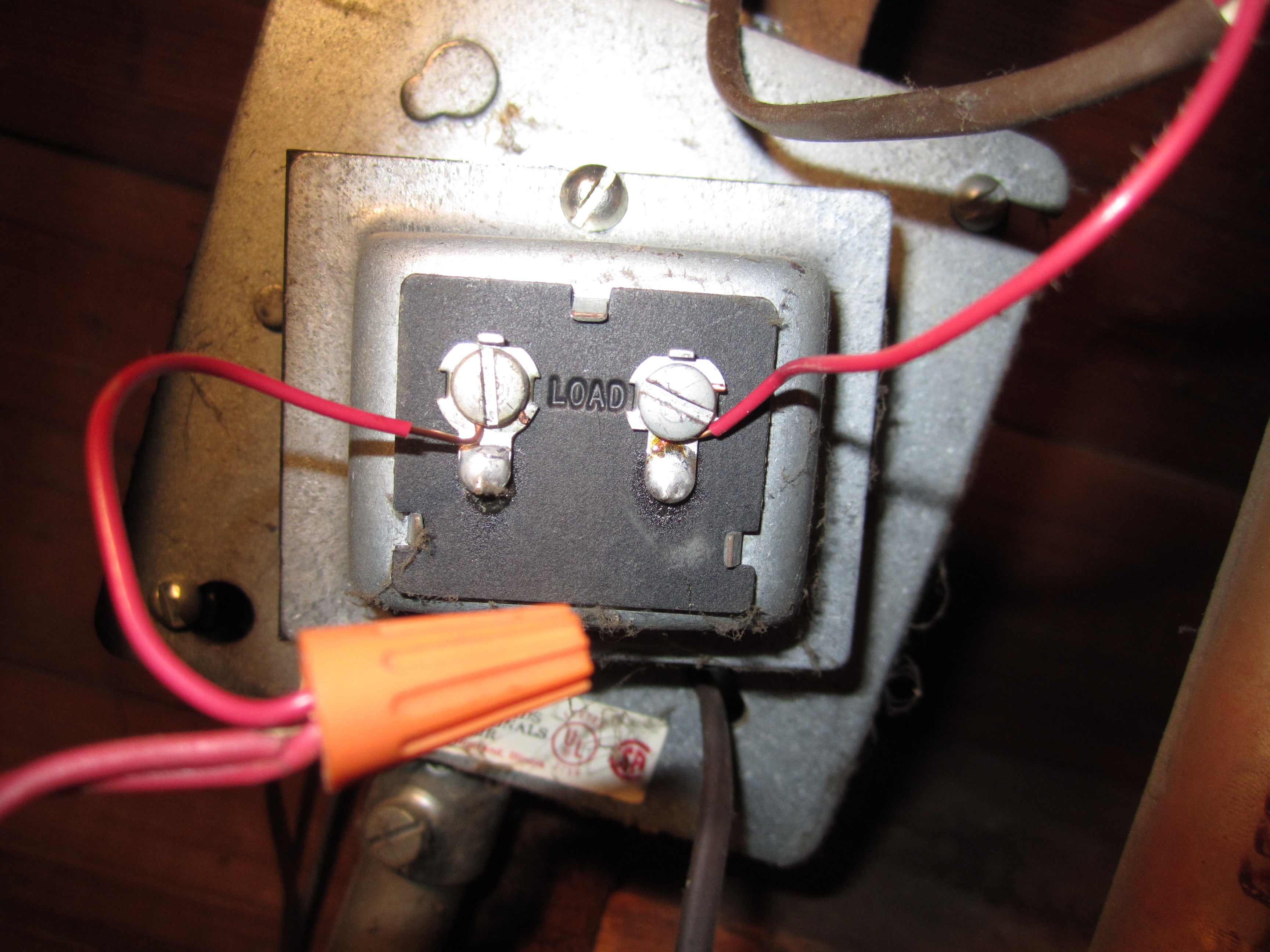
0 -
Jamie. I will be doing your tests today. I re-read and understand about the transformer. Thanks so much for staying with the thread.0
-
Jamie:
1. I read 29-25 volts at zone valve 1 on terminal #1. All other terminals were 0. So i'm guessing this should be rectified before going on.0 -
Yes. Sounds like wiring problems -- possibly in odd spots.Forrest said:Jamie:
1. I read 29-25 volts at zone valve 1 on terminal #1. All other terminals were 0. So i'm guessing this should be rectified before going on.Br. Jamie, osb
Building superintendent/caretaker, 7200 sq. ft. historic house museum with dependencies in New England0 -
The leads from thermostat (2) were initially reversed and we changed them making the color coding correct. I'm guessing maybe they were patched together someplace in the wall and reversed.0
-
At which point the question is -- if they were patched together, is the patch intact? A thermostat is nothing more than an on/off switch, and even if the colour coding for a two wire thermostat is messed up, it should still work. Unless there is no or poor continuity in the wires...Forrest said:The leads from thermostat (2) were initially reversed and we changed them making the color coding correct. I'm guessing maybe they were patched together someplace in the wall and reversed.
Br. Jamie, osb
Building superintendent/caretaker, 7200 sq. ft. historic house museum with dependencies in New England0 -
Jamie I believe we have tested the connections to both thermostats for continuity.0
-
I'm sorry to have to say this -- but at this point I'd have to get out there myself and test... which I'm afraid I can't do for you!Br. Jamie, osb
Building superintendent/caretaker, 7200 sq. ft. historic house museum with dependencies in New England0 -
Jamie I'm going to go over everything again Monday and hope I find something.0
-
Ripped all the old wires out and bought new wire and installed and same results.
question.
On the Aquistat board: 1 connection is labeled "TV" the other is labeled "T". Can someone tell me which one of these gets positive and which gets common? Or does it matter?
The transformer seems to be the most confusing part, everything makes sense to me and wiring seems to check good. In my system the transformer is constantly on and does not switch off with the main switch.
Thanks0 -
Time to call in some help...it's been a weekForrest said:Ripped all the old wires out and bought new wire and installed and same results.
question.
On the Aquistat board: 1 connection is labeled "TV" the other is labeled "T". Can someone tell me which one of these gets positive and which gets common? Or does it matter?
The transformer seems to be the most confusing part, everything makes sense to me and wiring seems to check good. In my system the transformer is constantly on and does not switch off with the main switch.
Thanks
There was an error rendering this rich post.
0 -
I would agree, I've been out of work for 2 1/2 years, have a Toyota with a broken frame and very little left in my bank account, but yes, I think I've worn everybody out. Thanks for trying.
Still no answer to my transformer connection at the aquastat.1 -
Finally had a Heating Pro come over, all the work I did was fine, turned out to be a loose connection on the aqua-stat.
Thanks for the support0


Categories
- All Categories
- 87.7K THE MAIN WALL
- 3.3K A-C, Heat Pumps & Refrigeration
- 59 Biomass
- 430 Carbon Monoxide Awareness
- 127 Chimneys & Flues
- 2.2K Domestic Hot Water
- 5.9K Gas Heating
- 121 Geothermal
- 170 Indoor-Air Quality
- 3.8K Oil Heating
- 79 Pipe Deterioration
- 1K Plumbing
- 6.6K Radiant Heating
- 396 Solar
- 16K Strictly Steam
- 3.5K Thermostats and Controls
- 56 Water Quality
- 51 Industry Classes
- 51 Job Opportunities
- 17 Recall Announcements