Welcome! Here are the website rules, as well as some tips for using this forum.
Need to contact us? Visit https://heatinghelp.com/contact-us/.
Click here to Find a Contractor in your area.
If our community has helped you, please consider making a contribution to support this website. Thanks!
Old vapour system
Options

5019
Member Posts: 4
I have come across this old vapour system that needs a boiler replacement. The existing boiler is not original to the system. The replacement boiler is 40 years old, but the system is about 110 years old. What is this device? It has three dry returns into the top.
0
Comments
-
maybe something like this....
actually .. i think it's this .. an automatic-pressure-regulator (http://screencast.com/t/YTMzNDU2) .. from PDF page 139 [url=http://books.google.com/books?id=PHhEAAAAMAAJ&oe=UTF-8]http://books.google.com/books?id=PHhEAAAAMAAJ&oe=UTF-8
i also found this .. found in Baldwin's Steam Heating for Buildings book .. PDF pg 126 ..
http://screencast.com/t/MDNhOTc5OWQt .. but I'm pretty sure this ain't it.
i think Dan spoke about this last night in his school .. but I don't remember exactly what he said about it... i remember him mentioning "bowling ball" copper float .. he said so much ..
below is the plaintext of the pages regarding "Vapor System" which reference this device ..
Vapor
Systems. Vapor heating is distinguished from vacuum heating, in that
the steam pressure carried in the supply piping is slightly above that
of the atmosphere, whereas in the latter system it is below atmospheric
pressure. Low-pressure steam, vapor, and a vacuum are merely relative
terms when applied to heating, the first applying to pressures of 1 to
5 pounds; the second to pressures of 1 to 5 ounces, and the last to any
pressure below atmospheric.
The system illustrated in Figs. 87, 88, 89 and 90
commonly operates under a pressure of 1 to 2 ounces. Temperature
regulation is secured by means of a fractional or graduated valve on
the supply end of the radiator, by means of which the amount of vapor
admitted
Fig. 87 Fig. 88
can be regulated to suit the requirements. A
sectional view of this valve is shown in Fig. 87. At the return end of
the radiator is a water seal (see Fig. 88), which balances any slight
difference in pressure between the radiator and the return main when
the supply valve is partially closed. One of the important features in
this system of heating is the method of automatically maintaining the
lowsteam pressure under which it operates. Figs. 89 and 90 are
sectional views through a "receiver," which is placed at the side of
the boiler. The main return from the radiators enters at the top of
receiver through a water seal (see Fig. 89) and passes into the
boiler through the return outlet at the bottom, the connecting pipe entering below the water line.
The air passes from the radiators with the
condensation and is carried off through a special pipe connecting with
the top of the receiver just above the water seal. This pipe first
enters a condensing coil for removing any vapor which may be present,
and is then usually connected with a chimney flue. The condensation
which forms in the coil returns to the receiver by gravity.
The action of the automatic-pressure regulator is easily explained
by reference to Figs. 89 and 90. The receiver is
open to the atmosphere and there is a free passage for the water to
flow between the receiver and boiler in either direction through the
return outlet at the bottom as indicated in the cut.
The slight steam pressure in the radiators and
piping is maintained by the water seal at the top of the receiver. When
the fire becomes too hot and the steam pressure rises above the point
for which the regulator is set, water from the boiler backs into the
receiver, the latter being at all times under atmospheric pressure. Any
rise of the water level in the receiver lifts the copper float, and by
means of connecting chains closes the drafts to the furnace.
A drop in pressure below
the normal has the opposite effect and opens the drafts. A safety
device for preventing the water from being forced out of the boiler and
overflowing from the top of the receiver, if the ash-pit doors should
happen to be left open, is shown in Fig. 90.
Should the float rise to a sufficient height to
lift the "adjusting rod" the relief valve will be opened and steam
admitted to the top of the receiver, thus relieving the excess of
pressure in the boiler and allowing the water to flow back from the
receiver through the return outlet.1-pipe Homeowner - Queens, NYC
NEW: SlantFin Intrepid TR-30 + Tankless + Riello 40-F5 @ 0.85gph | OLD: Fitzgibbons 402 boiler + Beckett "SR" Oil Gun @ 1.75gph
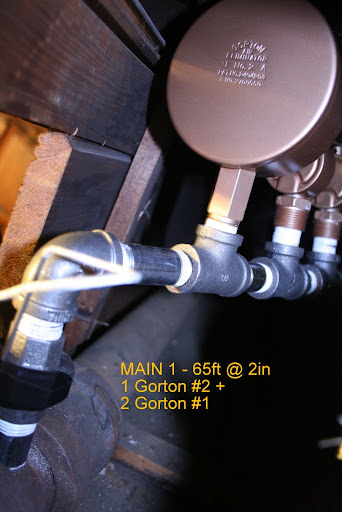
installed: 0-20oz/si gauge | vaporstat | hour-meter | gortons on all rads | 1pc G#2 + 1pc G#1 on each of 2 mains
Connected EDR load: 371 sf venting load: 2.95cfm vent capacity: 4.62cfm
my NEW system pics | my OLD system pics0 -
It probably is an old pressure regulator
but my question is, with three dry returns ending in that unit, how does the air get out? Maybe one of those "dry returns" goes into the chimney thru a condensing radiator?
Also, did you find a name on that regulator or on any of the original valves or traps in that system? This would help us ID it.
Where is this job located?All Steamed Up, Inc.
Towson, MD, USA
Steam, Vapor & Hot-Water Heating Specialists
Oil & Gas Burner Service
Consulting0 -
Old Vapor System - what next?
Thanks for the replies, but I still have more questions. There is no name on this water column anywhere. It is marked on the bottom front with the letters"OZ." Does this mean ounces? Above that lettering, there are demarkations labeled 1-9. There is also a ½" tapping below the letters "OZ" and what appears to be a support bracket of some type at the top of the casting and then a T with a ½" plug facing forward in the center dry return. I believe that this was for a gauge glass to mark the level in that water column. I cannot find any way of venting air from the system.
So my question is, how does this water column relate to the water level in the boiler? The water level that I am proposing to my client will be a different height than the current water level in the existing boiler. Also, what are the implications for replacing this boiler?
Additionally, this is the piping arrangement at the end of supply and return mains - approximately 40' from the boiler.0 -
Here is the picture in the correct orientation
Sorry, In my last post, the picutre was not in the correct orientation. Here it is again.0 -
Bet you're right
and I'll bet that one of those "dry returns" is actually the air line to a condensor, and thence to the chimney -- and the big cylinder looks remarkably to me like the draft regulator which was used on Broomell systems in the bad old days of coal. Could it be?Br. Jamie, osb
Building superintendent/caretaker, 7200 sq. ft. historic house museum with dependencies in New England0


This discussion has been closed.
Categories
- All Categories
- 87.3K THE MAIN WALL
- 3.2K A-C, Heat Pumps & Refrigeration
- 61 Biomass
- 429 Carbon Monoxide Awareness
- 120 Chimneys & Flues
- 2.1K Domestic Hot Water
- 5.8K Gas Heating
- 115 Geothermal
- 166 Indoor-Air Quality
- 3.7K Oil Heating
- 77 Pipe Deterioration
- 1K Plumbing
- 6.5K Radiant Heating
- 395 Solar
- 15.7K Strictly Steam
- 3.4K Thermostats and Controls
- 56 Water Quality
- 51 Industry Classes
- 50 Job Opportunities
- 18 Recall Announcements