What Is This (answered WATTS ISOTHERM) How do I fix this?

First off I am starting a new thread, hope that is OK here.
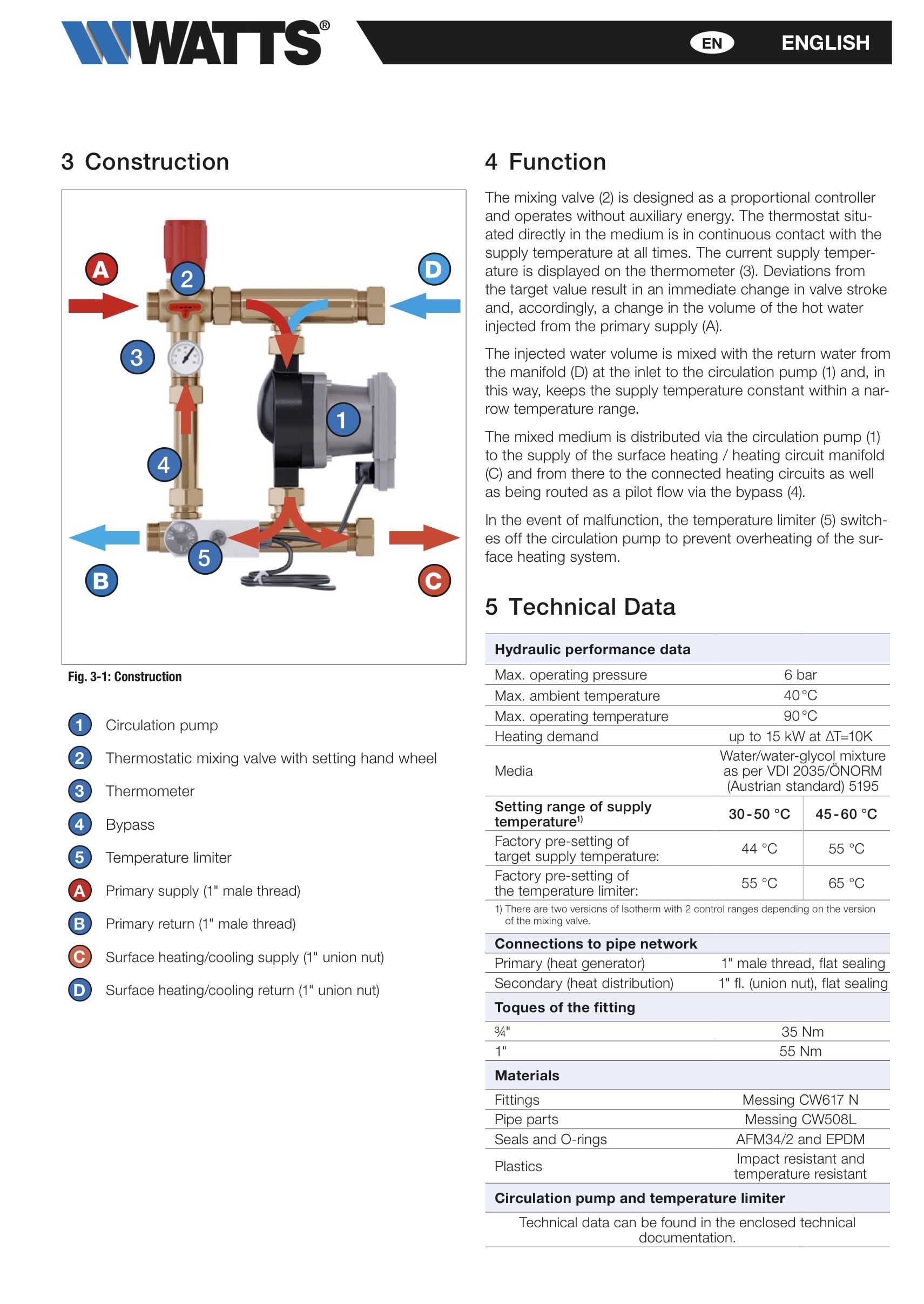
So many thanks last week to all who answered. As it ends up, I’m surprised that Google lens, and no one got this. I got to dad‘s yesterday, and of course he had the manuals from 30 years ago. It is a Watts Isotherm “control module” and after reading the summary below, I have a bit better understanding of what was intended and why I didn’t get it. Mostly, the three-way mixing valve here is running backwards with pilot flow, and as someone identified, the box with orange knob is an aquastat, however it actually was for HIGH temp protection, this thing does nothing for boiler return protection other than luck. Further the knobs on the isolation valves were correct because unknown to me dad”s zone valves are on his return manifold which leads to some issues in my mind since this things supply side manfold connects directly to the high temp return manifold.
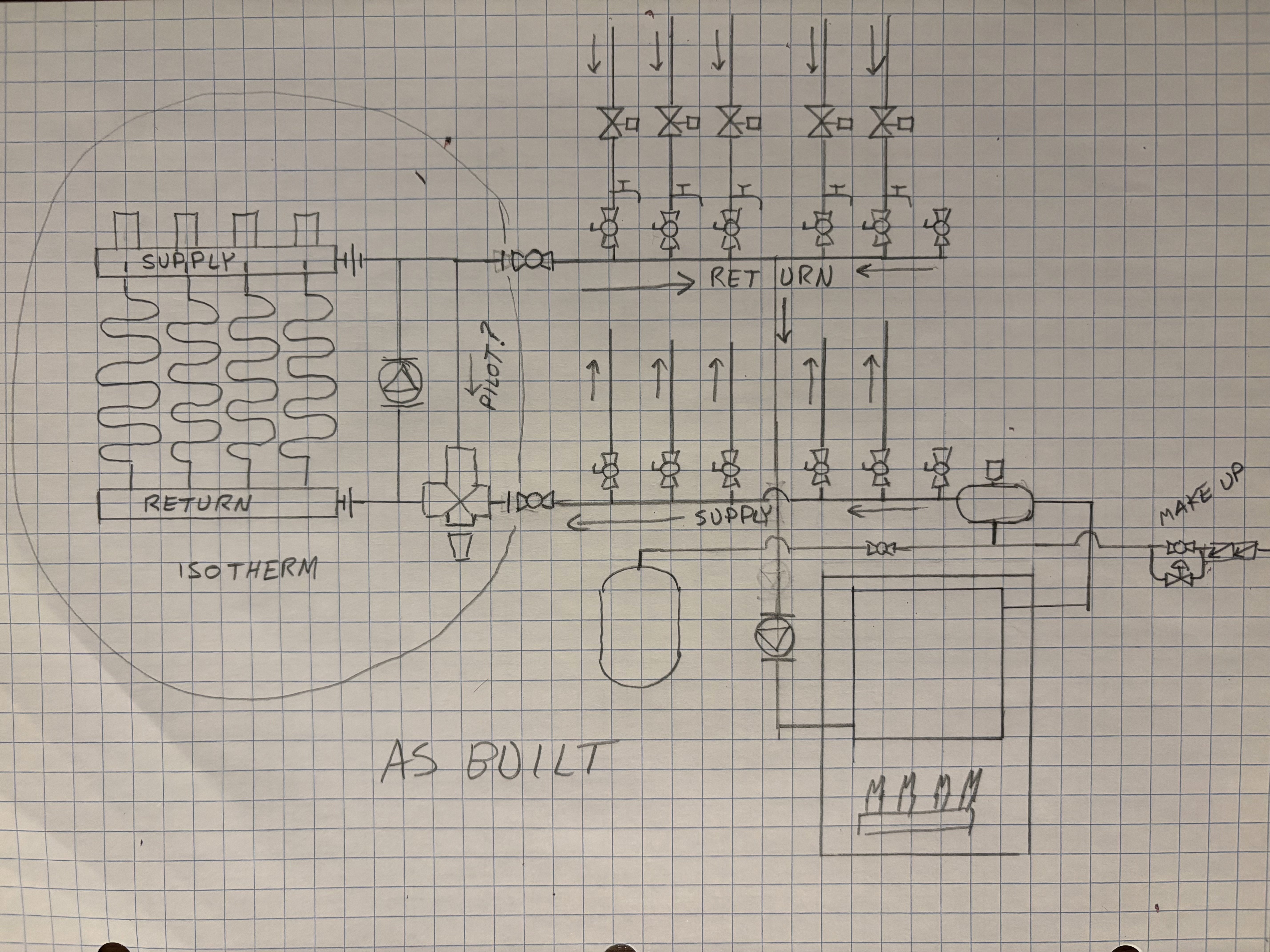
So now for an as built which might explain why it never may have worked properly. In his defense dad installed it the way his 5 page manual described. But looking online at a spec sheet on a Hungarian site, it is stated that the supply and return are supposed to be onto a primary loop, with this a secondary loop. Pardon the poor sketch, but this is what is there largely. All major components shown. Of note there are no differential pressure reliefs between either manifold set. The remote expansion tank and air scoop are also on the outlet side of the system/boiler circulator. The Isotherm circulator does run only with it’s loops, the system/boiler circulator with any call for heat. Both pumps are Grundfoss 15-58 both set to middle speed. The system is full of rust and sludge but is 30 years old. I am replacing the boiler like for like, Utica/Dunkirk cast iron, power vented, the original was a Sears branded Dunkirk power vented.
The thermostatic mixing valve on the Isotherm is a rock. Even after soaking for two days in CLR, judicious application of heat and penetrating oil, it is a paperweight. I see that it is easily available in the UK for 144 quid, but it does not exist in the US. Further, the circulator is probably questionable and the piping between them is severely corroded anyway. Plus again I don’t know if this truly worked as built anyway. .I have 10 days and the following things here at my disposal that I have collected over the years.
2 Honeywell AM101R-US-1 mixing valves (Cv 3.9)
A Taco I Series-S in 3/4 sweat (Cv 3.4)
A couple Taco 3196-1 differential pressure valves
Lots of new Grundfoss 15-58 pumps and a Taco 007-f5
A Tekmar 362 (which does power on, and was good 20 years ago when I took it out of service)
3 thermistors that should work more or less for either the I Series or the 362.
Fos context, the low temp is 4 loops of 1/2 Pex, 150-250 ft per loop.
Absolutely ANY suggestions for mixing and boiler return protection with what I got MUCH appreciated. I would very much prefer to not mess with either manifold, or the zone valves, though I could reconfigure them a bit. I have plenty of 1 1/4, 1, and 3/4 copper, a good assortment of pump flanges, etc.
Finally, I really don’t want to use the Tekmar 362 unless absolutely necessary, as there is no guarantee it still works, and I would hate to blow three or four days trying to figure that out. If somebody tells me hands-down, it is the smart choice, I’m receptive to it, it just may doom me.
Comments
-
the rule of thumb is IF the low temperature zone is 10% or less of the boilers output, return protection is not really needed.
Basically the boiler has enough capacity to raise the return when that zone runs
Not knowing the total heat load compared to boiler output, I suspect you are fine
Depending on how much upgrading you want to do!
Id like to see the circ on the supply after the expansion tank
Id rather the zone valves on supply to prevent ghost flow, but probably not worth changing it there have not been over heating zones?
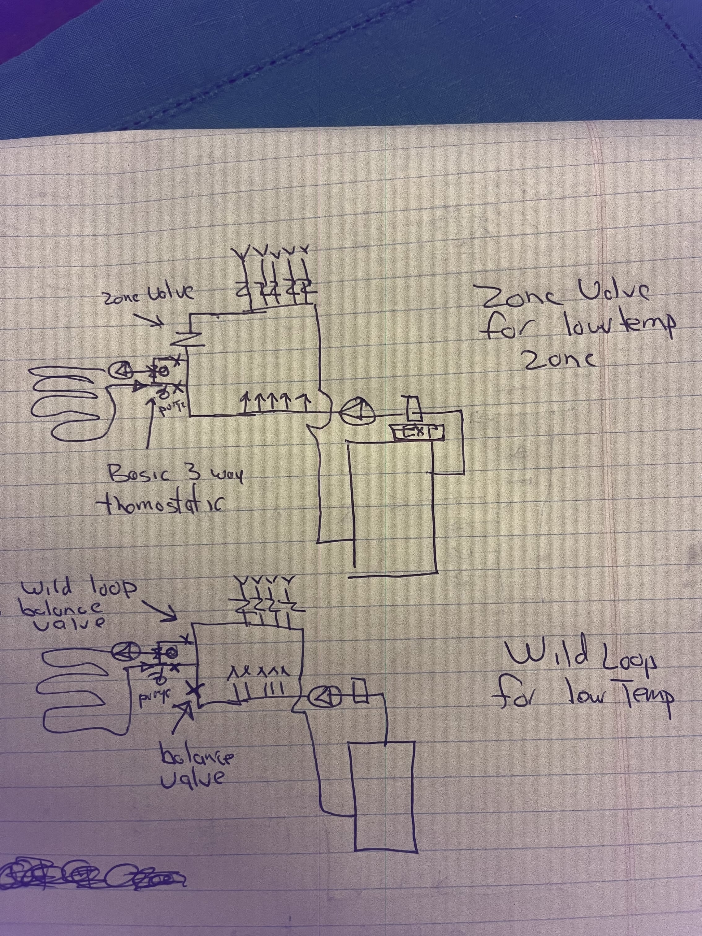
The HW am valve will work there are two piping options that still allow the radiant to run by itself, even if no hi temp zones are on.
The wild loop is the simplest, use a real balance valve, not a ball valve, so you have fine tuning across the wild loop
The additional zone valve , option 1 involves more wiring
You fix isn’t really too complicated
 Bob "hot rod" Rohr
trainer for Caleffi NA
Living the hydronic dream0 -
Bob, I didn’t call out on the pic, just drew them, but there are 4 zone valves on the low temp supply manifold, so does my return need to go through the additional zone valve or just dump into the return manifold? Dad (retired EE) has a bunch of switch logic running the pumps appropriately as it stands. You figure the 3/4” sweat AM1 is OK for the 8 gpm max flow?
I am a bit concerned about return as I downsized the boiler based on back calculating from his actual natural gas usage from a few worst months the last few years. I got a deal on a 112k, the prior had been 150k. I haven’t truly measured but back of envelope would suggest by sq ft living space could be right on the hairy edge, though it is mostly bare joist staple up so maybe better than I think.
I will definitely move the boiler circulator, no problem there. I could relatively easily reverse the high temp manifolds in total but the air bleeds on baseboards will end up in some funky places, and the house hasn’t had problems.Should I put the differential pressure valves in anywhere?
Thanks so much,John
0 -
ideally we would know what the total low temperature load is, btu/ hr.
Then decide if return temperature protection is a good addition.
Or record so actual run time data, which would take a heating load for a few hours, days.
Or an electrical solution with that orange aquastat at the boiler return.
It could drop off the radiant pump if return drops. Not my favorite method , but a good what if solution. It could be added later if needed.
As far as dead heading, the zone valves, via a relay, call on any zone pump? So the pump should not run without some-valve(s) open ?
Ideally an ECM delta P circ on the zone valve loops, someday. They deal with 3 issues, over pumping, no flow, and 50% less power consumption
Starting in 2028 all small circs will be ECM motors. More choices and lower prices perhaps
This shows a return protection 3 way valve if you are more comfortable
 Bob "hot rod" Rohr
trainer for Caleffi NA
Living the hydronic dream0 -
No I will take you guys word on it, I get the staple up PEX isn’t losing much heat.
I just cleaned up Bob’s diagram so I’m sure I have this right with a last couple stupid questions.
2 of the questions there on the diagram, the high temp manifold is stepped down to 1” at that end, so without a zone valve there do I just loop the ends together with the 1” copper? Is the loop out to the thermostatic mixing valve “closely spaced T’s” by the standard rules, does it matter? Finally the most stupid question, which side of the thermostatic mixing valve is hot and which is cold in Bob’s picture (and my clean up). Does that even matter with the AM1.
Thanks again.John
0 -
yes the tees close together, about 6" allows you to catch both sides of the mix valve with and ell or street ell.
The mix valve should be labeled H & C, probably in the forged body.
Hot supply from boiler feeds H on mix valve.
C port gets return from radiant and goes back into the wild loop. See below
I would make the "wild loop" 3/4" and add a balance valve to adjust just enough flow to handle the radiant needs. Trial and error on that adjustment.

A valve like this that allows accurate flow adjustment.

 Bob "hot rod" Rohr
trainer for Caleffi NA
Living the hydronic dream0 -
Thanks Bob that is what I was wondering your original sketch above had the hot and cold coming off the “loop” reversed in orientation and the balance valve on the “wrong” side and that was throwing me. I think you posted it 1am or so (my time at least :-). I don’t realistically know the chances of getting a real balancing valve in town, and even Amazon is slow to him, so for the moment it may have to be something less. I do have a couple real globe valves in his old stuff, vs of course a ball, but I get that you can’t really much throttle a ball accurately as it gets closed. Robertsons may have a real one though, who knows.
0 -
Amazon to the rescue, sufficient I presume?

will get the boiler physically in today/tomorrow and the high temp side up and running, and rough in whatever I think makes sense for the low. Cleaned up a bunch of old slow leaks with the high temp zone valves today and a butchering of the black iron from when a “professional” installed a new water heater for them. Must not have owned a set of pipe dies, or noticed the set literally sitting under the boiler/water heater pedestal.
John 1
1
Categories
- All Categories
- 87.8K THE MAIN WALL
- 3.3K A-C, Heat Pumps & Refrigeration
- 59 Biomass
- 430 Carbon Monoxide Awareness
- 133 Chimneys & Flues
- 2.2K Domestic Hot Water
- 6K Gas Heating
- 124 Geothermal
- 170 Indoor-Air Quality
- 3.8K Oil Heating
- 79 Pipe Deterioration
- 1.1K Plumbing
- 6.7K Radiant Heating
- 396 Solar
- 16.1K Strictly Steam
- 3.5K Thermostats and Controls
- 56 Water Quality
- 51 Industry Classes
- 51 Job Opportunities
- 18 Recall Announcements