relay trane furnace

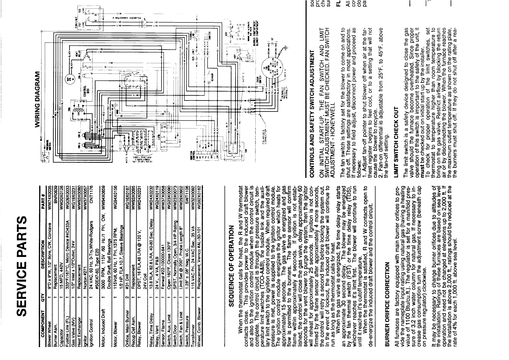
Tuc0808942a1 trane furnace does anyone have a wiring diagram for this unit
I need a relay 21d131200p22
Comments
-
How old is this furnace? I dont see that model number in the dealer database. The only information I have that is close to your model number is this https://www.trane.com/WEBCACHE/18-CD19D5-1_01011993.PDF
I'm not sure that you can open this link but this is the front page of the manual: Is the model number possibly TUC080C942A1 ? look closer at the rating plate/sticker.
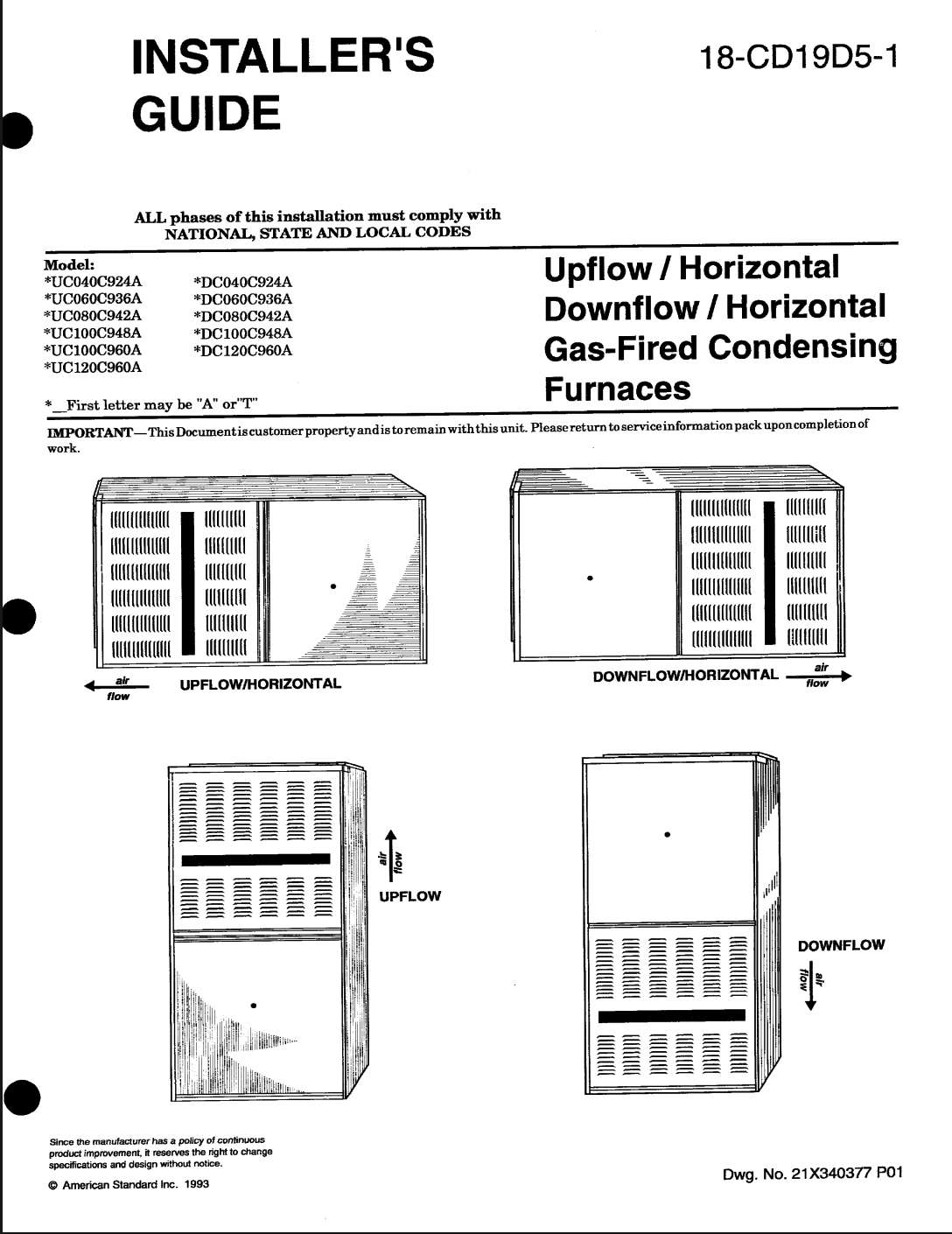
Does this look like your furnace?
Edward Young Retired
After you make that expensive repair and you still have the same problem, What will you check next?
0 -
A little more searching found that there is no relay with the part number 21d131200p22 on that furnace. can you take a photo and post the photo on this forum. I found that this furnace uses a control board that may be called a fan timer or an integrated furnace control. if there is an additional control with that part number added to operate the system in some way, it was not supplied by Trane or they do not use that part number to identify it.
Edward Young Retired
After you make that expensive repair and you still have the same problem, What will you check next?
0 -
This relay was listed for a Trane TUC080B942A1
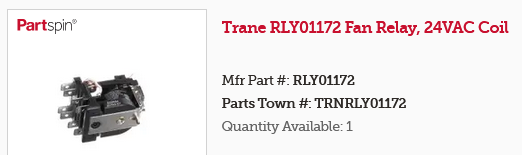
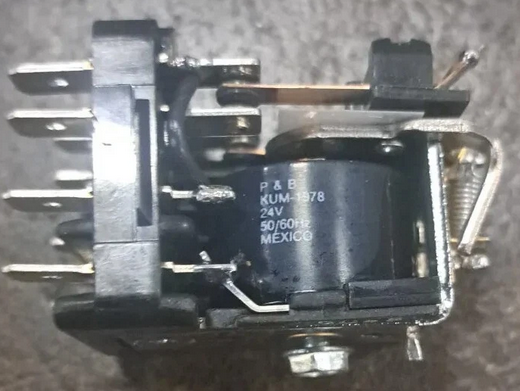
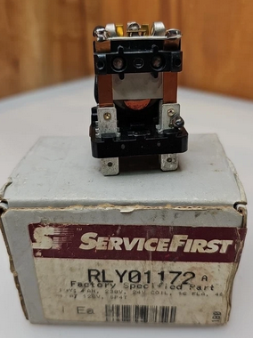
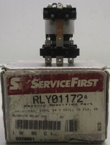
ebay has this listing; Trane Rly01172 Rly1172 Control Relay 21d131200p22 WW24X0231
Supplyhouse.com

https://www.supplyhouse.com/Trane-RLY01172-Fan-Relay-230V-16A-SP4T-24V-Coil
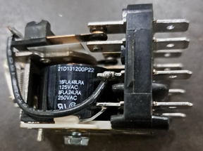
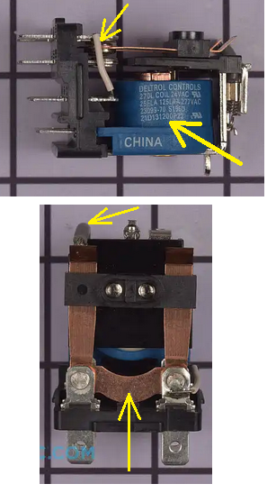
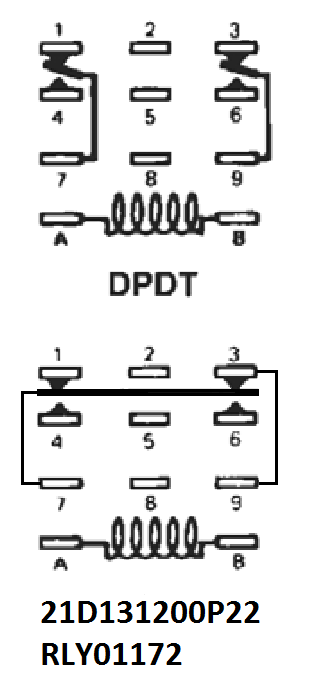
It looks to me like it is a modified DPDT relay not SP4T. More like a Single Pole Double Throw with a second set of contacts and there is also an extra wire jumpered to one of the contacts, Odd.
So one armature or Single Pole, N.C. has 3 wiring connections (via 2 contacts) and N.O. has only 2 wiring connections.
National - U.S. Gas Boiler 45+ Years Old
Steam 300 SQ. FT. - EDR 347
One Pipe System
 2
2 -
Great find by @109A_5
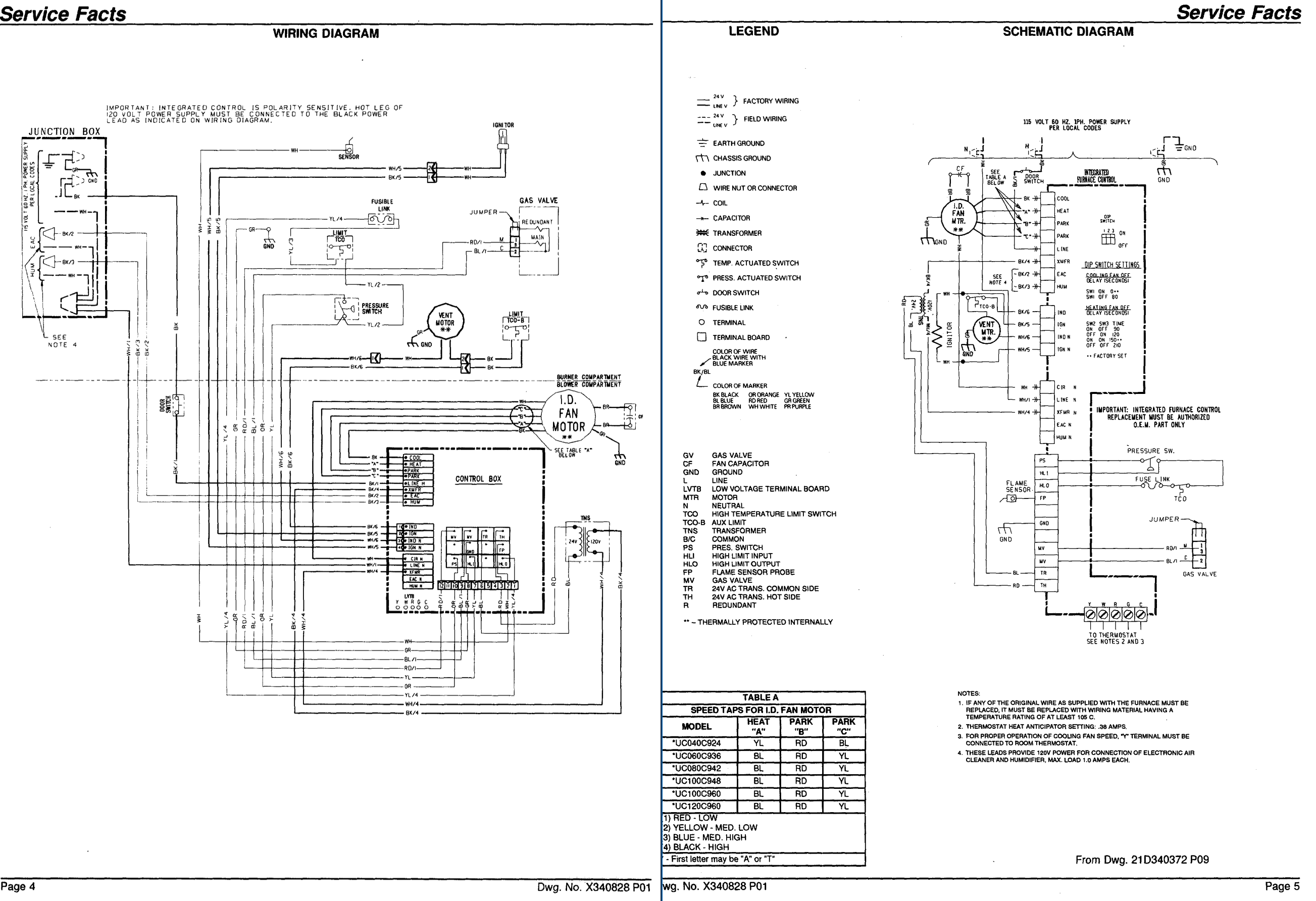
Here is the link to the wiring diagram.
If you cant open it because you must log in, I will copy each of the 4 pages and post them here shortly.
I think this is your wiring diagram.
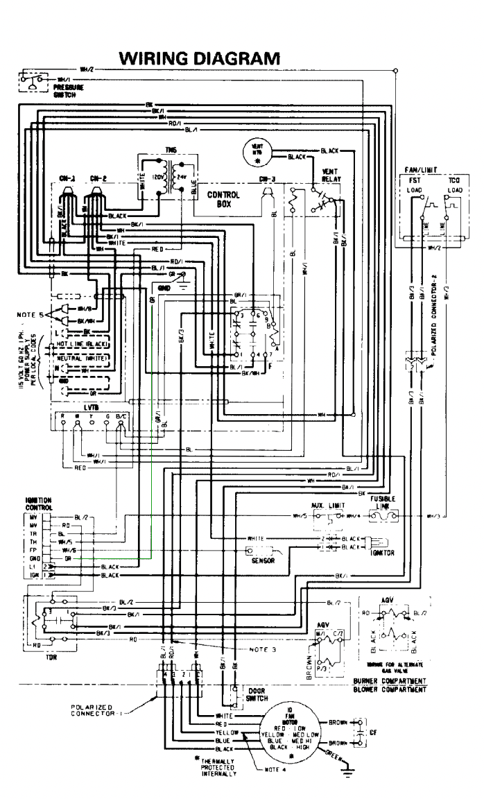
looks like there are a lot of white wires with numbers to determine which one is which. Trane does that on commercial stuff a lot. I didn't realize they did it on residential stuff. I think this is from the 1990's. I didn't work on many Trane or Am Std residential until after 2008.
Hope this helps!
Edward Young Retired
After you make that expensive repair and you still have the same problem, What will you check next?
0 -
The way that relay is drawn in the diagram above that @EdTheHeaterMan posted is kind of wierd.
It is basically a DPST relay with 24 volt coil. 1 pole is NC and 1 pole is NO.
The relay coil gets powered from G on the stat and closes the NO contacts to run the blower on high speed.
The heating contacts on the relay are locked open when G calls which is normal.
During heating the relay is not used except the power is run through the NC contacts. The TD relay get powered when the gas valve is powered to start the fan after a delay or the fan is started from the fan switch in the plenum.
I don't know what the wire to terminal "F" is or what the two wires (the other end of wire "F") and the neutral that says 'See note 5" is for. maybe a humidifier?
0 -
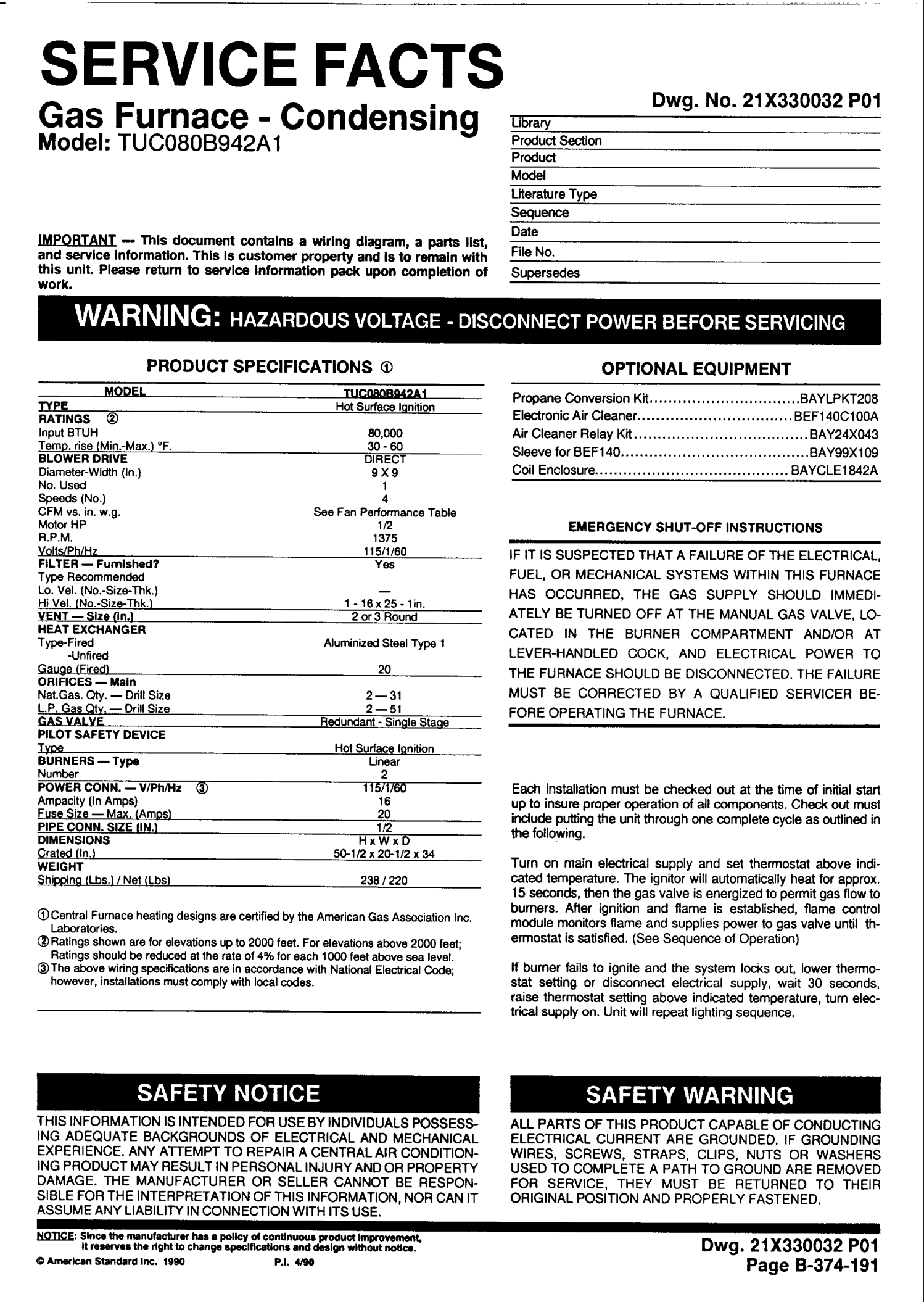
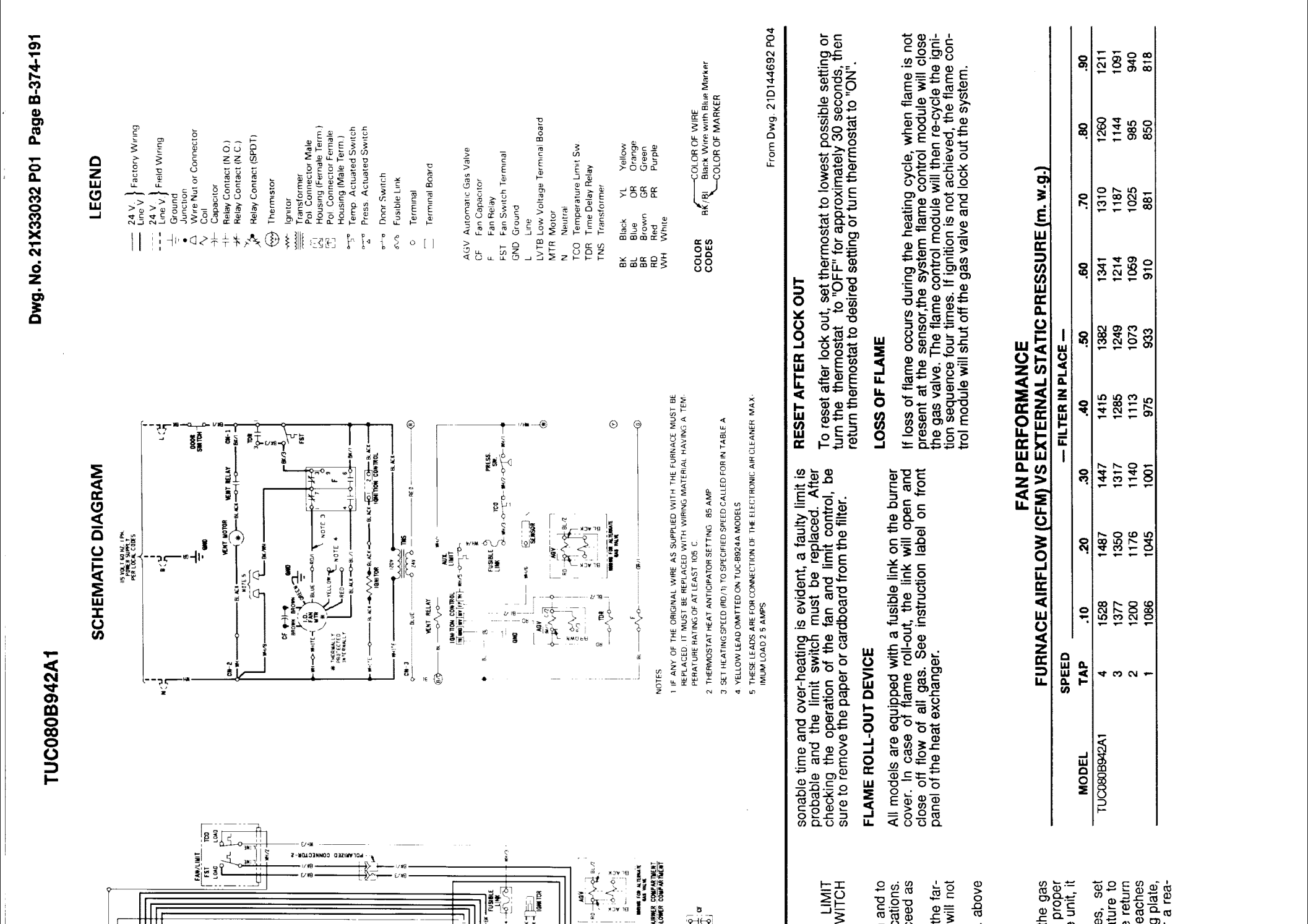
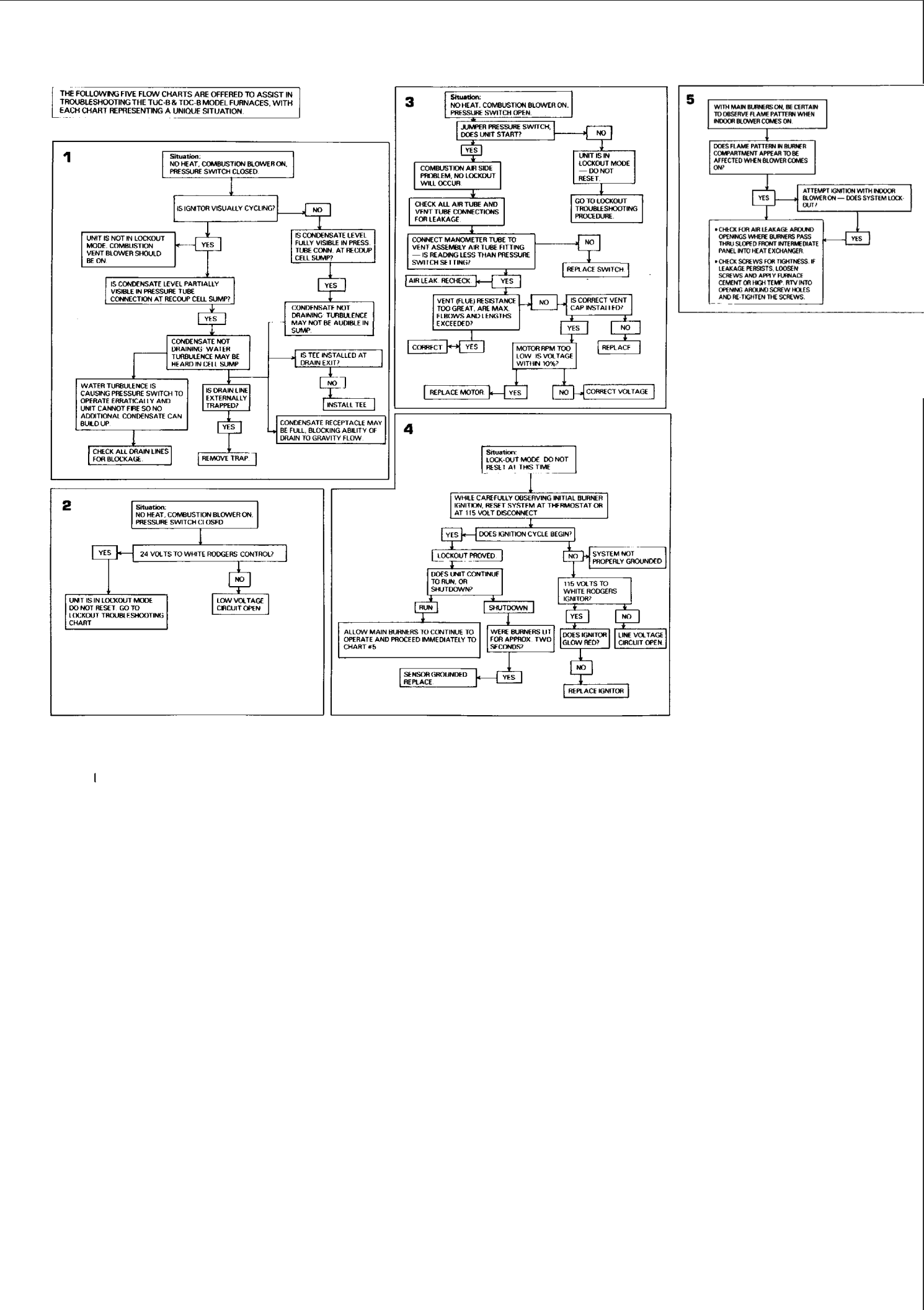
Here is the 4 page service fact sheet from Trane
Edward Young Retired
After you make that expensive repair and you still have the same problem, What will you check next?
0 -
Ok. Note #5 is for an electronic air cleaner. Don't know why they have the double contacts on each pole, one set of contacts would do the same thing.
Any 24 volt relay with contacts large enough to handle the blower motor will work. Double Pole single thrown with 1 set of open and one set of closed contacts or use two relays
0 -
Although the ebay listing also includes the WW24X0231 number, so all 3 are probably the same;
Trane Rly01172 Rly1172 Control Relay 21d131200p22 WW24X0231
the DPST designation in the documentation description seems odd and/or incorrect.

As far as @EBEBRATT-Ed 's description;
" It is basically a DPST relay with 24 volt coil. 1 pole is NC and 1 pole is NO. "
I can see how he came to that conclusion by looking at the drawing.
However when you actually look at the way the relay is built it is a modified DPDT relay. It has two modifications away from the common DPDT relay. Terminal 9 is the second Pole and is disconnected from that purpose and jumpered to terminal 3. The actual poles are bonded together and both are terminal 7.
After the modification there is effectively only 1 pole (two poles bonded together), with redundant NC and NO contacts and the redundant NC contacts 3 & 9 go open in relationship to 1 when not in the NC state. 3 and 9 are always closed (the other jumper). So after the modification there is one Armature or a Single Pole (the two original poles bonded together), N.C. has 3 wiring connections (via 2 contacts) 1, 3, 9 and N.O. has only 2 wiring connections 4, 6. Connection 1 to 3 and 9 go open when the NO contacts are closed.


I'm sure at some point this relay served a specific unique purpose to solve a control issue. Now in this case it just looks like an expensive replacement part. A like DPDT relay could easily be modified if you have those skills and equipment.
National - U.S. Gas Boiler 45+ Years Old
Steam 300 SQ. FT. - EDR 347
One Pipe System0 -
That was my point although I only alluded to it. No need to buy or search for that exact relay especially if it cost prohibitive. Any DPDT with a 24volt coil could be used if it will handle the motor load
0 -
Terminal 9 on this wiring diagram is not used. therefore that jumper is not necessary on this furnace. That seems to allow for a substitute relay. As I see it a simple general purpose relay can be used. The relay connects terminal in the normal position (coil not energized) 1, 3, 7, & 9. Terminal 9 is not used, 1 is connected to the Med Hi or heating speed of the blower motor. 3 is connected to the Fan terminal on the fan limit switch and 7 is connected to the EAC if there is one (Note 5). If there is no EAC on this system then #7 has no need for an external wire connected.
When energized then terminals 4, 6, & 7 are connected while 1 and 3 are not connected inside the relay. That will take the Fan motor High speed (or cooling speed) to connect directly to L1 power that is connected to Terminal 6. again if there is no EAC then the 7 terminal has no external wire connected.
So the question is: Is there anything like a EAC or 120V indoor air quality devise connected to terminal 7? If not, then we can eliminate the need for that exact relay. A much less expensive relay can be used for that same purpose. Since #9 terminal is not used , then the general purpose relay can be substituted for the replacement:

But you really need to know what you are doing to make this happen. Then you need to mark the wiring diagram with your changes something like this:

And here is the closeup of the relay modification.

here is the lowest cost relay that will do this for you: Supco 90-340
Edward Young Retired
After you make that expensive repair and you still have the same problem, What will you check next?
0 -
I just don't agree with this description you provided.
" It is basically a DPST relay with 24 volt coil. 1 pole is NC and 1 pole is NO. "
You could build it with a SPST NO and a SPST NC relay with dual isolated contacts (or probably more commonly called or DPST NO and a DPST NC or 2PST NO and a 2PST NC) but that would get more complicated to wire.
It appears they also leverage (in this case) that whichever Throw is Open at any given time there is also isolation between those contacts. Which you would not have if a (single) DPST type relay is used. And we don't know if Note 5 is being used.
They are actually switching 4 different things, into two different states, two motor speeds and two motor control strategies and Note 5 is also available as long as the motor is energized.
National - U.S. Gas Boiler 45+ Years Old
Steam 300 SQ. FT. - EDR 347
One Pipe System0 -
After a 2d look.
This relay does 2 things if you don't consider an EAC
Running on cooling or if the stat is turned to "fan on" when "G" on the stat pulls in the relay both NC contacts between #3  open breaking the blue wire to the motor which "Locks out" the heating speed. At the same time #6 & #4 close powering the black cooling speed on the motor which then runs on high speed.
Running on heating with "G" deenergized the fan will run on the blue "medium high" speed with the motor being powered by the time delay or the furnace fan switch whichever calls first.
If there is or is supposed to be another pole for the EAC I am not seeing that contact between terminals # 9 and #7 on the relay and it would make 0 sense to me to have that.
Wouldn't you want the EAC to work on heating and cooling? And the #3-#9 jumper does nothing.
What is not shown is something that would make sense is if #7 (the EAC) is connected in the middle of both sets of contacts on the relay then the EAC would work on heating and cooling.
In my first post (before @EdTheHeaterMan posted the Trane info) I mentioned not knowing what the EAC wire was because I didn't have that info. I called it the "F" wire because there is an F next to it. We did not know what "note 5" was at that time.
What i was trying to say is with no EAC any 24 volt relay with 1 NO contact and 1 NC contact would be all the OP would need. Thats what I said in my post of 8/8
1 -
Agree @109A_5. The EAC can operate whenever terminal 7 is powered. This can happen either when G energizes the circuit through terminals 4–7–6, or without a G call when the furnace fan control closes the 1–7–3 circuit during normal heating operation, that may be controlled by a fan-limit control or a fan timer. So a much less expensive relay can be used.
like a Supco 90-340. As long as 9 is not connected to anything then the Supco #1 and the #4 on the general purpose relay can be used by placing a jumper between them and calling it #7 for the purpose of this diagram. And if #9 is used in a different capacity then you just need to connect what is connected to #3 and #9 on the Trane relay to the #5 on the Supco 90-340. It does the same thing that way.
It takes some thinking to follow the circuit on the system and on the diagram, but it is do-able.
Edward Young Retired
After you make that expensive repair and you still have the same problem, What will you check next?
0 -
" Wouldn't you want the EAC to work on heating and cooling? "
Any time the motor is running terminal 7 is Hot or energized (in reference to the neutral, Note 5).
" And the #3-#9 jumper does nothing. "
The connection of #3 to #9 is apparently for another purpose not used with this unit.
" What is not shown is something that would make sense is if #7 (the EAC)
is connected in the middle of both sets of contacts on the relay then
the EAC would work on heating and cooling. "Oh, I thought that was very obvious. Either looking at the wiring diagrams (especially the ladder diagram). Also the pictures of multiple build iterations of the relay shows the two poles (armature) bonded together. Also terminal #7 (in reference to the neutral, Note 5) is effectively across (or parallel to) the motor in either control state.
National - U.S. Gas Boiler 45+ Years Old
Steam 300 SQ. FT. - EDR 347
One Pipe System1 -
@EdTheHeaterMan As much as a Supco 90-340 may be the least expensive replacement option I would only use a DPDT relay with a socket in this situation. Without a socket it may be too easy for the next guy to screw it up.
National - U.S. Gas Boiler 45+ Years Old
Steam 300 SQ. FT. - EDR 347
One Pipe System0 -
Then purchase the socket when you rewire for the new relay. Q633A1003 As far as the age of that furnace is concerned, that relay will outlast the heater in my opinion. so maybe a little money wasted but it is a good exercise in doing it better than the next guy, but also a wasted expense in my opinion. Especially when trying to keep costs to a minimum.
Edward Young Retired
After you make that expensive repair and you still have the same problem, What will you check next?
0 -
In my meager attempt I could not find a socket for the Supco 90-340. With the cost of the Q633A1003 you might as well put in the correct replacement relay.
And yes a new relay may easily outlive the equipment.
National - U.S. Gas Boiler 45+ Years Old
Steam 300 SQ. FT. - EDR 347
One Pipe System1



Categories
- All Categories
- 87.8K THE MAIN WALL
- 3.3K A-C, Heat Pumps & Refrigeration
- 59 Biomass
- 430 Carbon Monoxide Awareness
- 133 Chimneys & Flues
- 2.2K Domestic Hot Water
- 6K Gas Heating
- 124 Geothermal
- 170 Indoor-Air Quality
- 3.8K Oil Heating
- 79 Pipe Deterioration
- 1.1K Plumbing
- 6.7K Radiant Heating
- 396 Solar
- 16.1K Strictly Steam
- 3.5K Thermostats and Controls
- 56 Water Quality
- 51 Industry Classes
- 51 Job Opportunities
- 18 Recall Announcements