7 Zone Hydronic System with Knight Firetube Boiler - System Redesign

Long time lurker, first time poster.
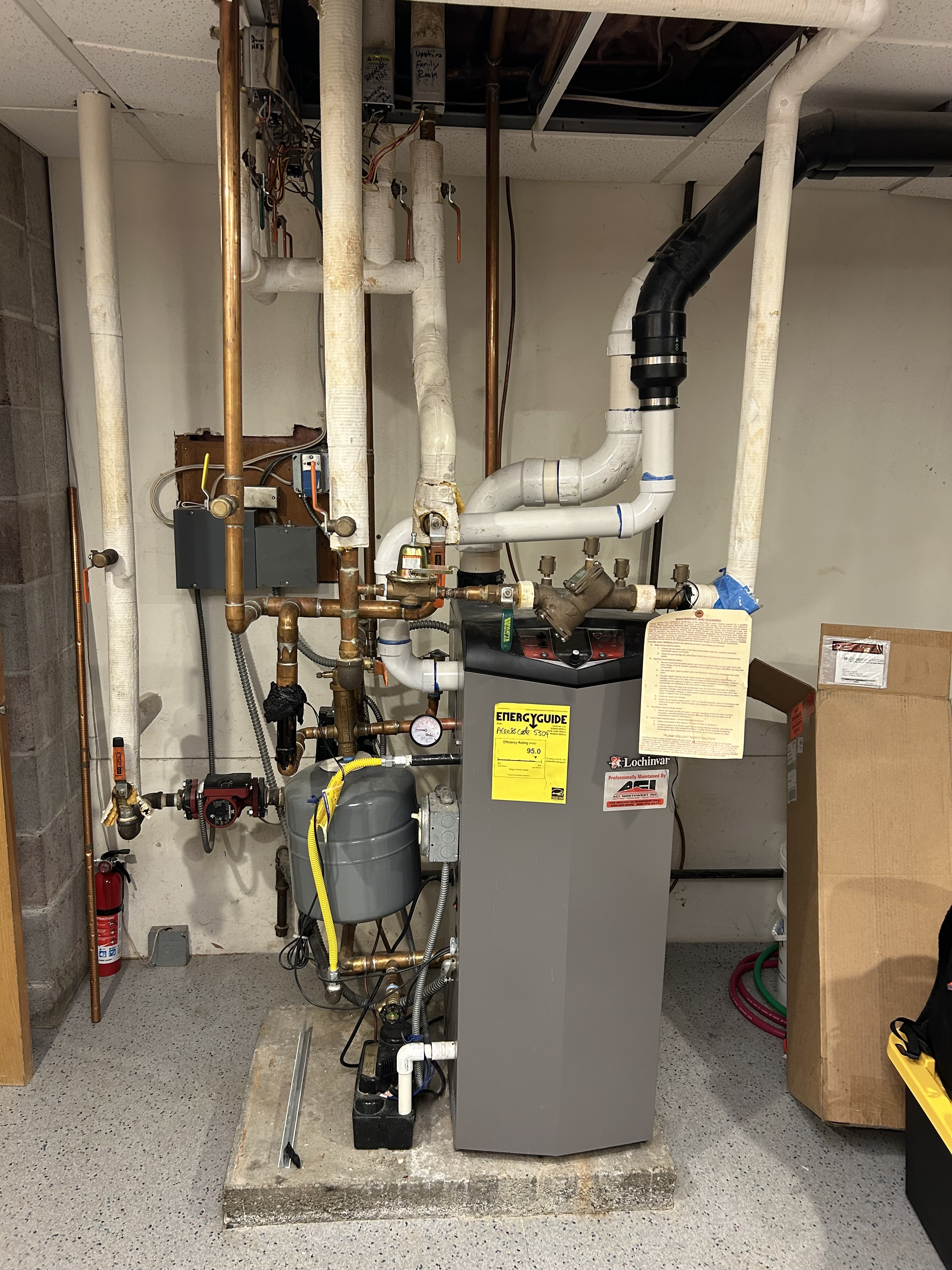
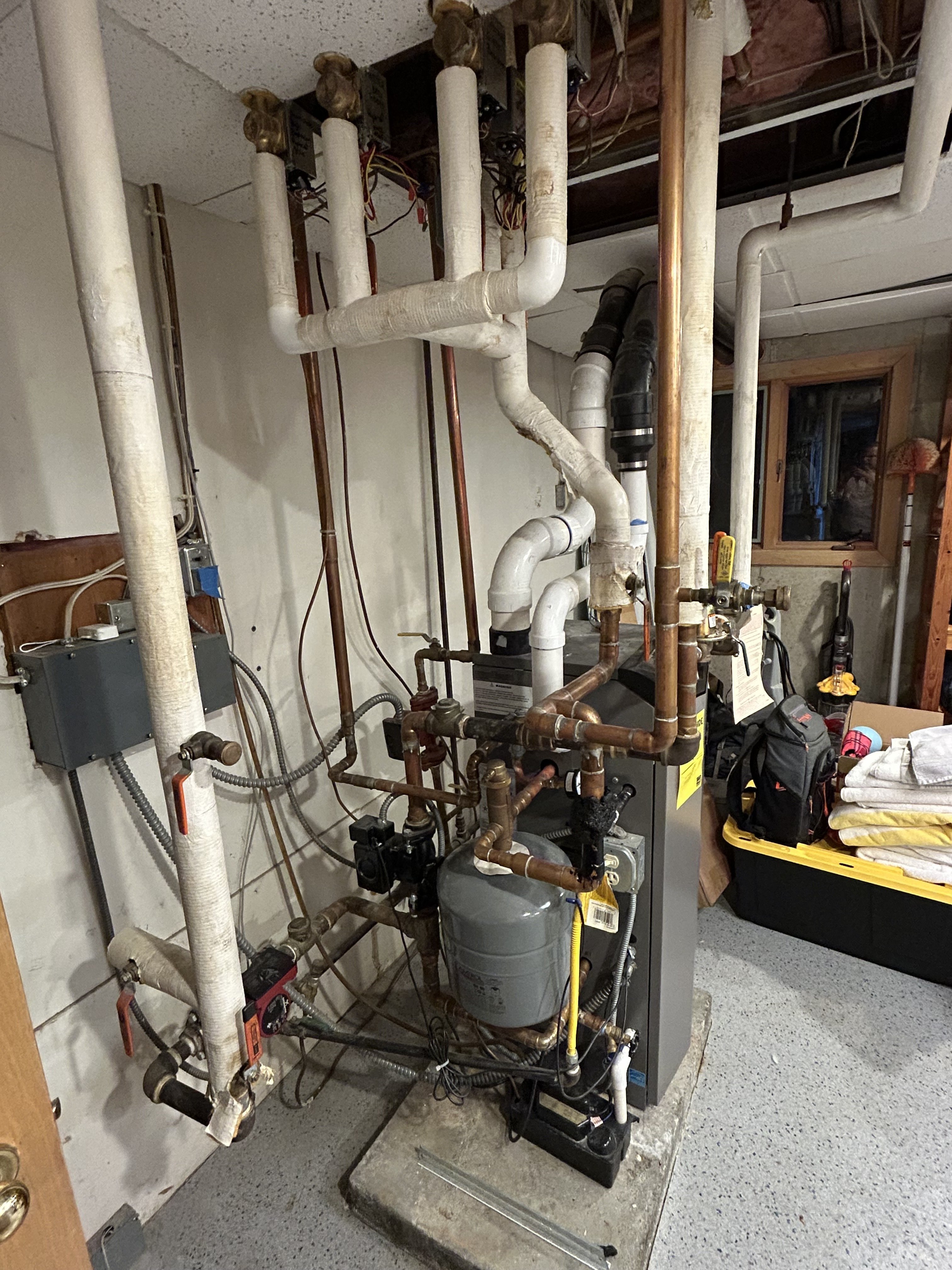
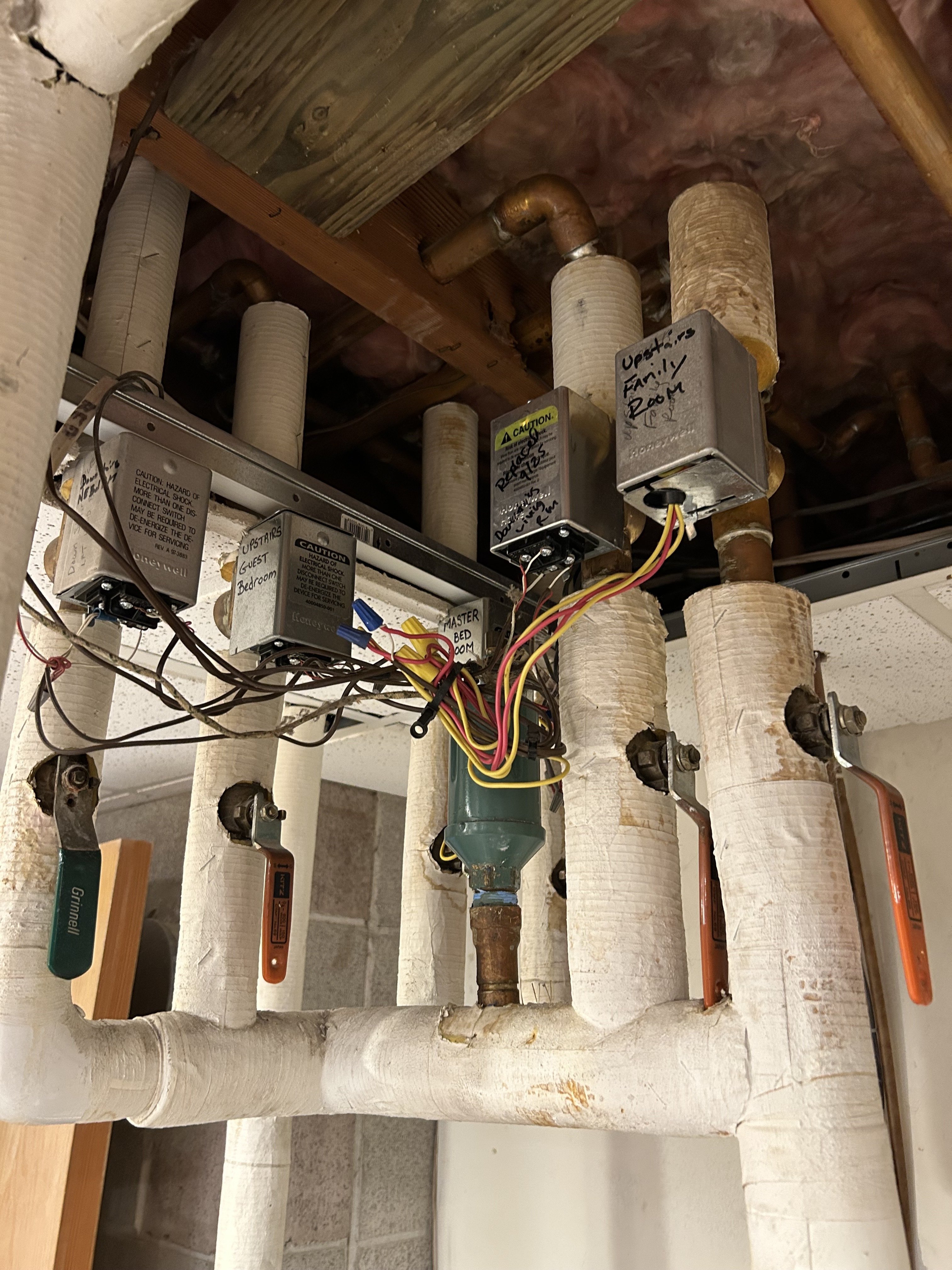
I have a 1966 home in North Idaho, that for some reason has a hydronic heating system for its primary heat source. I think it used to be heated with heating oil, but now has a Knight Firetube boiler (KHB110N). I have 7 total thermostats, and 6 zone controllers in the utility room and 3 return lines, each with their own pumps. I also have an automatic, pressure-valve controlled, fresh water fill line. It was installed professionally, but it looks like something a 3rd grader would do. I think there's been too many cooks in the kitchen, and they've all be operating under a low-cost model. Also, there have been additions on the house, and I think that has contribued to the issue. My goal is to fix all of this, make my house look a little nicer, and get some of my utility room back. I hope that if I every sell the place, someone doesn't look at it an think "What the heck is this?" like I did. It doesn't help that there are very few professionals in the area who can deal with this. Virtually nobody heats their home with hydronic heat in North Idaho, aside from the newest homes with heated floors and garage de-icing.
I've cleaned out and replaced components in the boiler, replaced the old honeywell zone controllers (not the valves themselves), and moved some of the heating units around the house by draining the system and changing things. I've also been messing around a lot with PEX-A and running new plumbing around my house and garage. I'd really like to take this up a notch and organize, reroute, and modernize this mess, but I don't REALLY know what I'm doing. My hope is to get a neat wall-array with manifolds, shutoff valves for the zone controllers, and ideally an actual 7th zone controller for the 7th zone, rather than whatever is rigged up now. I'm a mechanical engineer by trade, and really enjoy tinkering. I don't see any reason why I can't sweat on PEX A fittings to each of my pipes up top, run all of my lines neatly to a wall panel, add some valves for future maintenance, and add a ton of organzation and space to my room. There's a few places my knowledge fails me, and I think this group to weigh in.
- Can I do this? Am I missing something huge?
- What are everyone's favorite zone controllers? I have old honeywell ones now, but I don't really love them, and it doesn't look like many people use them today. Are there any ones I can use with pre-made manifolds for my application? I see the Taco Zone Sentry and the Belimo Zone Tight? What should I use here? I have basic digital Honeywell Home thermostats.
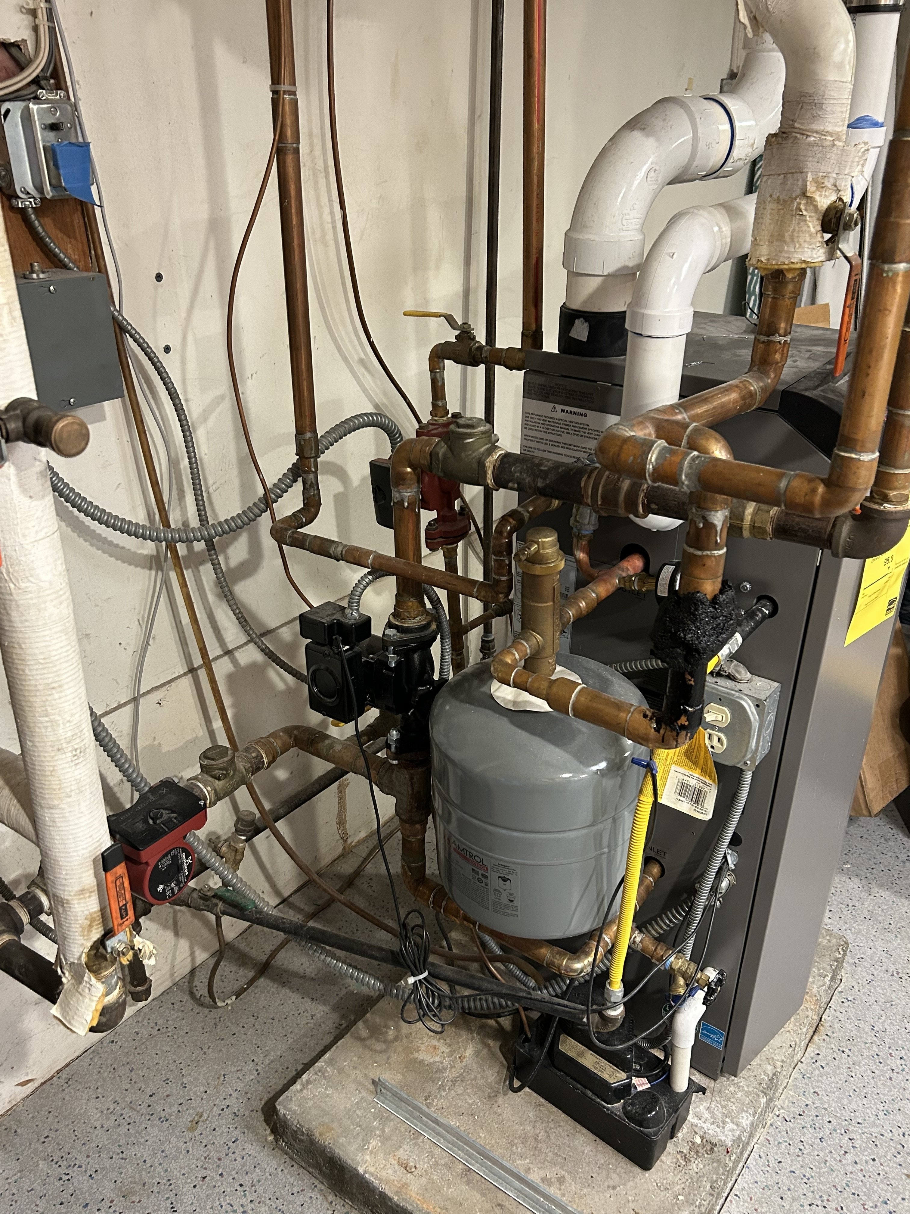
- I don't really understand my return pump strategy. The variable speed pump that looks like a "main pump" really only comes from the loop for the addition. The other two fixed-speed pumps take return water from the upstairs and downstairs, each as a collector. I don't think I would have 3 return pumps for 7 zones if we built this today. I'm not sure I have any reason to change what they have, but this would be the opportunity to do it. Either way, I think I only have access to 3 zone returns.
- I have a WIDE variety of copper sizes. My Knight Firetube has a 3/4" inlet and 3/4" outlet, but my main trunk line out of the boiler is 1" and feeds qty 6 3/4" zones. Is there a good reason everything can't be 3/4 inch?
- Am I smart enough to figure out this wiring and add the 7th zone properly? Right now I think the 7th zone is basically an On-Off switch for the system, with all other zones closed. This doesn't seem like it should be right, and I can't quite figure out why they would've done it this way. Maybe there's an integrated zone controller in the Knight or some other control mechanism that only handles 6 zones?
Can you all help me and give me a little inspiration? All of the photos I see of nice manifolds are not done with independent control valves, but rather proportioning valves. Am I over-simplying this?
Thanks in advance.
Comments
-
it is probably 1” piping connections on that size Knight.. 1” is adequate for 8,9 gpm or so, so the near boiler piping could be 1”
The Knight comes with a variable speed circulator intended for a boiler loop pump.
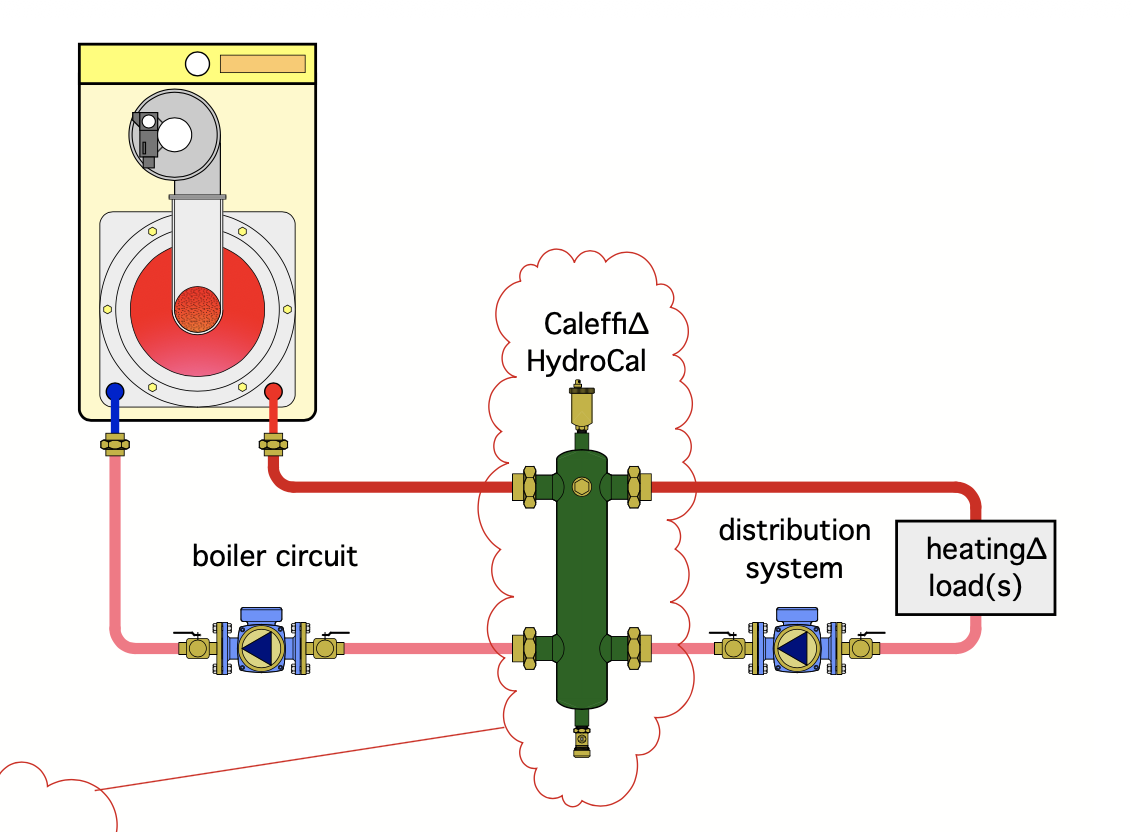
It could be piped with close tees or a hydraulic separator.
Pretty nice pipe insulation job, probably not 3rd grader work😙
The backflow preventer is a few sizes too large.
It comes down to how much repiping and $$ you want to spend.
Does it heat properly? Have you got into the control to see what functions are enabled?
That is a very nice boiler and should run efficiently piped and controlled properly.
As for the wiring, what is the 7th thermostat connected to?
Caleffi is my recommendation for all components, in addition to being some of the best components, they are my employer.
If you are near resort towns and $$, I would imagine there are some knowledgeable hydronic folks around. A nearby hvac plumbing supplier would know some of the hydronic companies.
Bob "hot rod" Rohr
trainer for Caleffi NA
Living the hydronic dream
 3
3 -
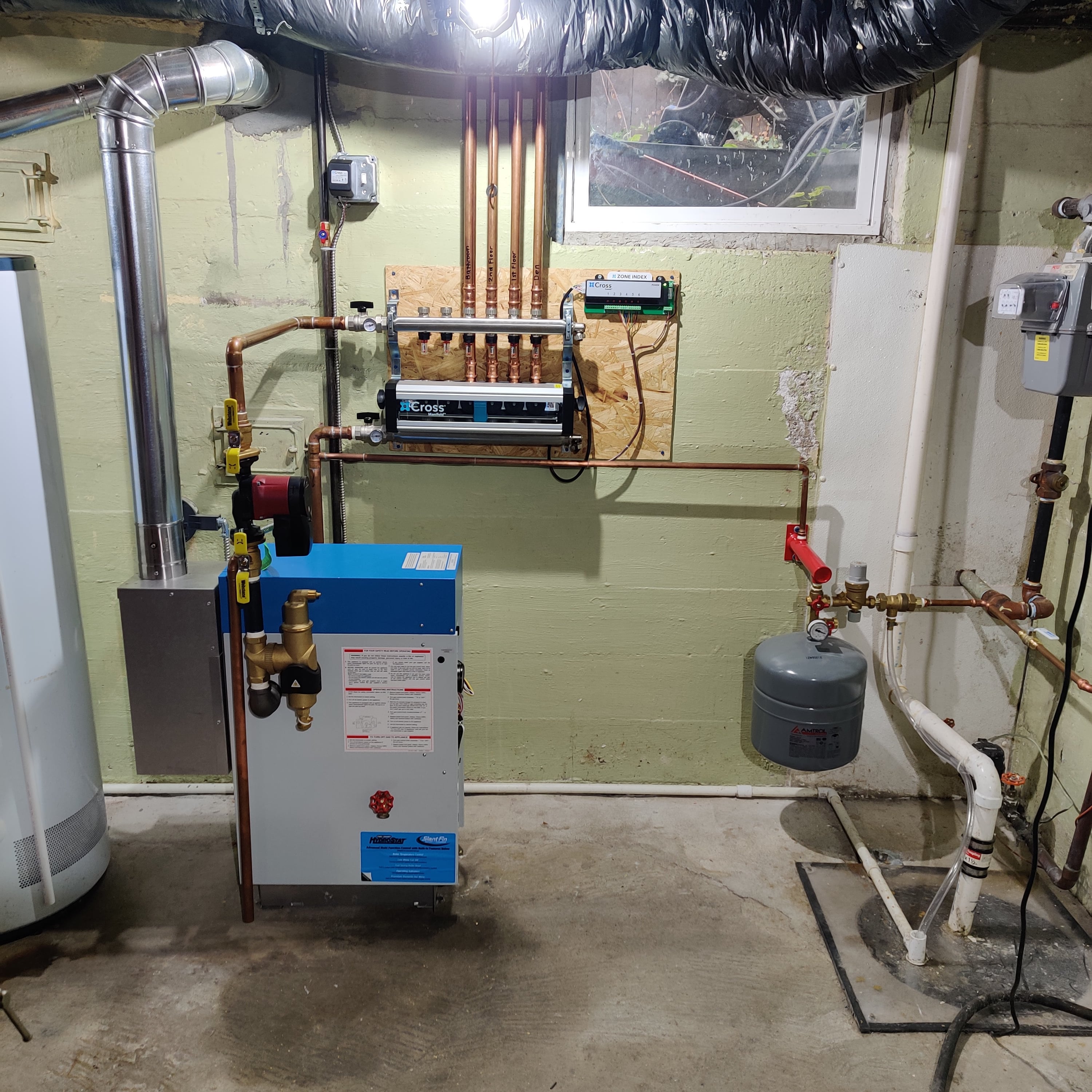
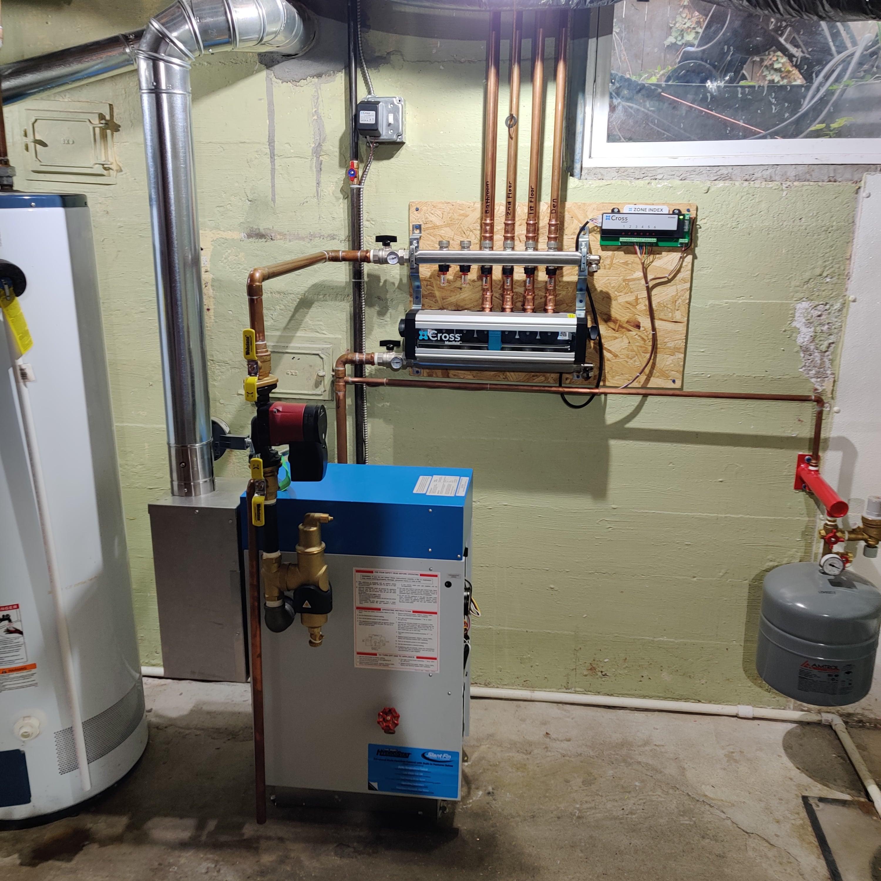
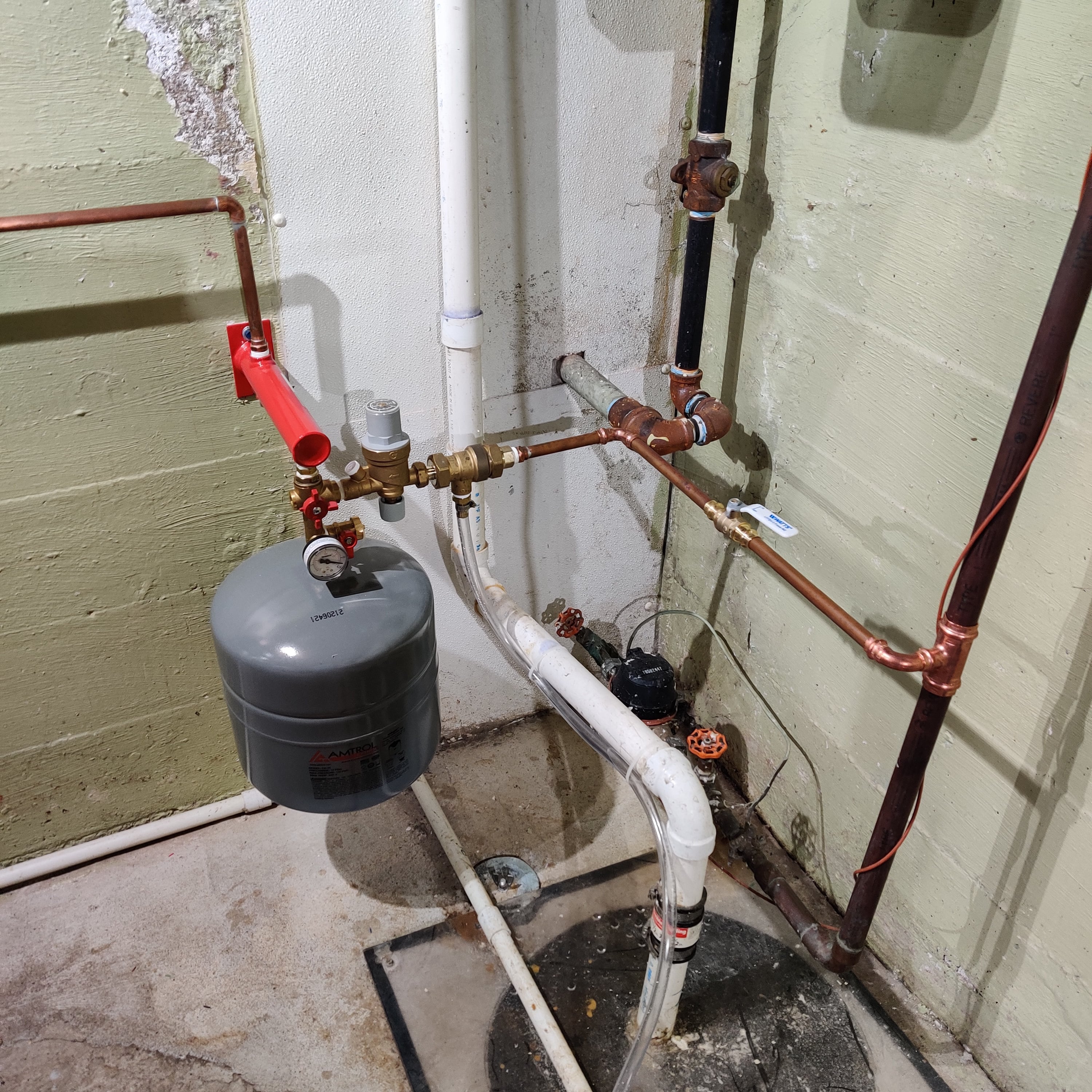
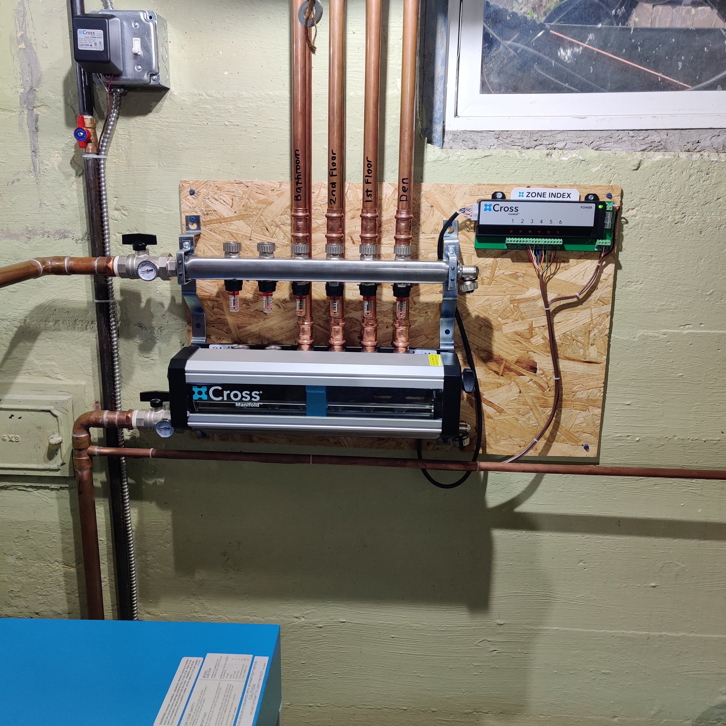
Since you are a Mechanical Engineer and not from the HVAC field like myself, you would probably feel comfortable using stepper motors such as myself. They are somewhat new to the hydronics market, so a lot of HVAC technicians are a little scared of them. You should look at the Cross Manifolds, https://www.supplyhouse.com/Cross-Manifold-CROSS8-8-Loop-Stainless-Steel-Manifold-Package-w-Control-1-2-PEX
Here is a system I did about four years ago and it runs great. They come with adapters for copper and PEX A. It uses a 1" manifold and the branches can handle 3/4 " copper loops got for around 40,000 btu's each. You can use one of the newer delta pressure circulators to make things also simple. I also like the Caleffi and Webstone products coming from an Engineering quality point of view. I have not used their Air separators though. I like to use a dirt/mag separator to protect the magnets in the variable speed circulators. With the Knight boiler though you might look into Caleffi's Hydraulic Separator which might make everything simpler.
Noel
0 -
So the inlet and outlet from the Knight are 3/4" (unless my eyes deceive me). If that were the case, I assume there's no need to have 1" anywhere else in the system, right?
The pipe insulation on the home-made manifold is pretty nice, I think that is from the original system/plumbing job. There is some of the black putty-like insulation around the outflow temp sensor, that USED to actually hold that sensor in place. It would get hot and droop over time and the sensor would fall off and the whole system would shut down. Me, being a super genius (not) hose clamped it on, and have kept my house from freezing every time that fell off, while on vacation.
I've actually turned off the automatic fill function, so the backflow preventer is mostly irrelevant. Prior owners had an incident, where the system shut off while they were out of town, the water in the system froze, and about 7000 gallons of water flooded the house through the automatic refill. I suspect the outbound temp gauge fell off and the system errored out and shut off, allowing the house to cool and freeze. Their solution was antifreeze in the system, which is fine, but didn't fix the underlying issue.
They system does heat effectively, but hard to say if its proper. I have a heck of a time getting air bled out when I drain the system. The 3 return lines for 6 or 7 zones I think provides extra backflow paths within the system, which makes it hard to push air out. The little air bleeder valves are not enough to clear all of my air traps, and I'm looking to drain the system here this week and add more in places where air is more of a challenge. BTW, someone needs to invent coin air bleeders with barbed outlets for little drain hoses, so I don't get water all over my hardwoods.
As far as local experts, I called the installers to come do service on my Knight, and I really wanted them to do and exhaust gas evaluation and make sure it was running smoothly, they said they could service the boiler, but that they "didn't really do that" when it came to flu gas analysis. They also told me my system was set at 145F, which was "a little on the high side". When my house was cold last winter I turned it up to 160F and it stayed plenty warm after reading that most people run systems at 180F. Needless to say, they didn't inspire much confidence, and that was the better of two hydronic "specialists" I have had out. The other one checked the pressure in a reverse osmosis pressure tank, water came out the Schrader valve, and they said that the pressure looked good. They haven't come back and I have a new pressure tank now.
As far as my thermostats, it seems like they all control valves appropriately, but not all of them are capable of turning the system on independently. For example, if only my bedroom calls for heat, it'll kick the system on and open my valve, but the thermostat in the downstairs living room will turn the valve on, but if it calls for heat the system does not turn on until another room also needs it. This is mostly not an issue when its 20F outside, but obviously isn't an ideal mode of operation. Additionally, the "addition" room doesn't even have a valve at all, it just turns the system on when that thermostat calls for heat. Again, I'm no wiring expert (but I have dabbled there too, rewiring outlets, adding 3-ways, and lights) but that doesn't seem like appropriate operation. The only variable speed pump is attached to the return for that loop. Interestingly, that room doesn't seem to overheat.
So, part of my reason to want to mess with it is to get it working properly, even though it does heat my house now. I think investing something like $5k into this would be worth it to have it be more easily serviceable, understood, and to take up less space in the house. Right now its kind of a visual and operational mess. I did save some money by doing the full 5-year service on the boiler myself last year (new main seals, igniters, cleaning, sensors) and got the cool Lochinvar bag with my $700 kit (they're making some money over there).
0 -
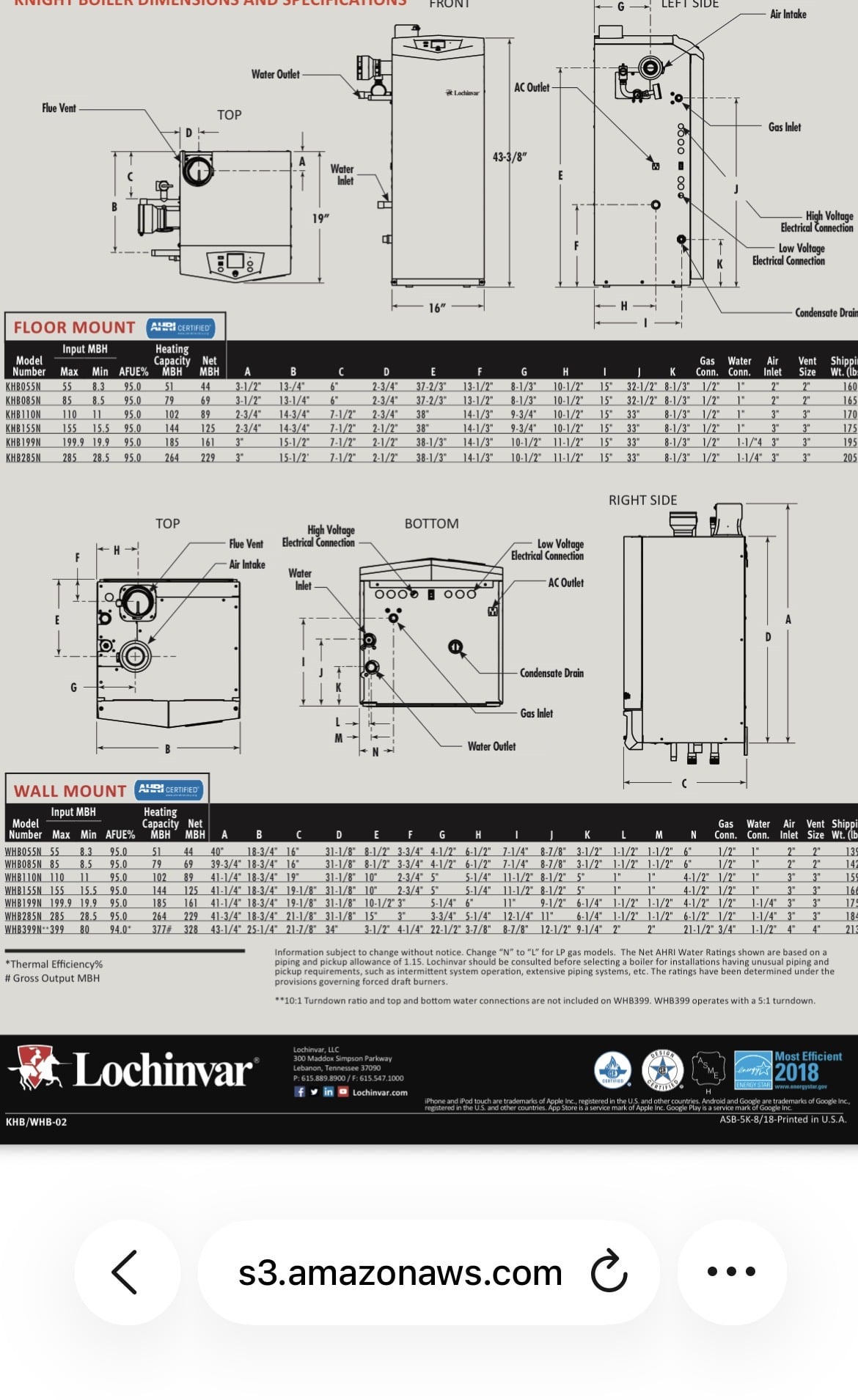
The Knight Firetube boiler (KHB110N) has 1" NPT. ports.
Take a look at
pages 35 through 38, figure 6-14
The Knight boiler will plumb directly into the separator and after your initial purge you should not have to worry about air in the system. With the Cross manifold, you can run your thermostat wires directly to its controller and it will control your boiler along with the system pump for your seven zones. You can also hang them on your wall and run either PEX or copper to the seven zones. You can also use a tank bracket like these
https://www.supplyhouse.com/Expansion-Tank-Brackets-20311000
and mount your tank and fill system to the wall also cleaning up the room as you want.
0 -
Even the smallest Knight 55 has 1” connections, larger sizes have 1-1/4
usually the control logic is, is thermostat opens a zone valve or turns on a zone pump, and also calls the boiler on
If the boiler is up to the setpoint temperature it will not need to turn on with the zone valve or pump until the temperature drops
So it depends on where it is in the sequence when you are checking
It is good to run that boiler on its ODR outdoor reset function. This allows the boiler to adjust its operating temperature based on outdoor temperature. A sensor is placed on a north wall outside, connected to the boiler. This sensor comes eith the boiler
Purging is a multi step project. First purge with a pump and hose into a bucket, to keep the glycol
Purge one zone at a time until it runs clear glycol. If it is cloudy it still has entrained air
Once all zones are purged fill to at least 12 psi
The automatic air purger will handle small bubbles the comes out as the fluid heats
Go to the Lochinvar website to find a factory trained service person , or the factory rep for your area.
You need a qualified person to adjust and confirm combustion settings
Usually a person with that skill will know how to adjust the boiler control setting.
Lochinvar has great phone support from my experience and plenty of videos to help you through control settings. It would be wise for you to know how to adjust snd troubleshoot we the the control readout and data logging
A lot of things in you pic tell me someone knowledgeable piped it. Long sweep ells on the venting, pipe insulation, straight piping, a good air purger. Im not fond of those check valves at the pumps The wrong type and way oversized for the gpm
You do not want an autofill and connection to water if it will stay a glycol system. Use a glycol feeder That boiler has a low pressure cutoff if it would ever drain completely down
Bob "hot rod" Rohr
trainer for Caleffi NA
Living the hydronic dream0 -
For some fast answers, this booklet might help you understand what you have. It is really dumbed down for the boiler technician who has no engineering background. So it was not written for you, but there are some concepts that are explained in easy-to-understand language. You may not like the writing style, but I kinda' like it. Zoning Made Easy
It explains that you need at least 1" pipe to move 80,000 BTU of heat from the boiler to the radiators when all the zones are open and operating. A 3/4" pipe can only move about 40,000 BTU.
So, based on how much heat is required by any particular zone, you may be able to pipe a radiator loop or zone with 3/8" PEX that connects to a 1/2" pipe at the first tee fitting. Then the manifold can increase to 3/4" at some point after several radiators or zones are sharing a common pipe. That could be handled by one circulator as long as the total connected radiation is less than 40,000 BTU to the return pipe.
Do that two or three times, and when you connect the return pipes from each circulator to the boiler, you will need to increase from 3/4" to 1" on the manifold before entering the boiler return.
As you leave the boiler in the supply piping, you can do the same thing in reverse, starting at 1" pipe and reducing the pipe size as you pass each tee branch into a radiator or zone. Look at the NET rating on the boiler that is what you need to pump out to the radiators. The Input is what the gas pipe must be able to handle since that is how big the flame is going to be. The difference is the efficiency loss from the flame to the vent pipe and again from the water in the boiler to the heat in the pipes and radiators. So your 110,000 BTU input boiler will only do about 89,000 BTU of heating in your home. the rest is efficiency loss of one kind or another
Edward Young Retired
After you make that expensive repair and you still have the same problem, What will you check next?
0 -
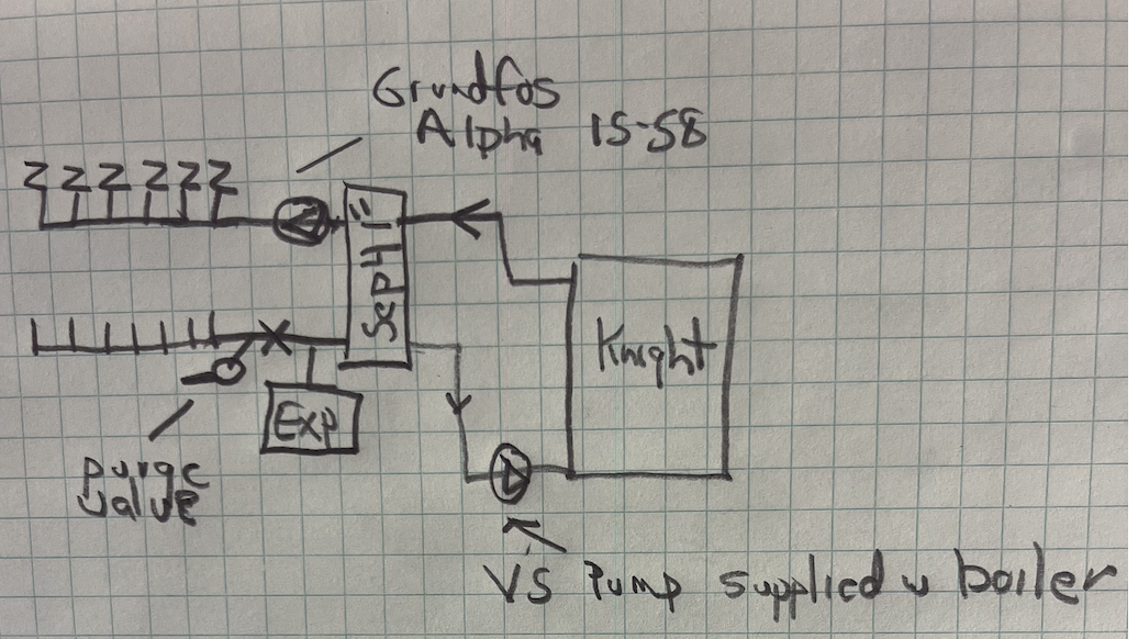
My suggestion if you want to repipe near boiler.
A 1" Sep 4 hydraulic separator, 11 gpm rated. Boiler pipes with 1" copper. This hydraulically disconnects boiler from 7 zones.
Use the boiler supplied Grundfos as the boiler pump.
On the distribution side a pumplike a Grundfos Alpha 15-58. This pump will adjust it's speed automatically as zone valves open and close. So you pump the required gpm at any time .
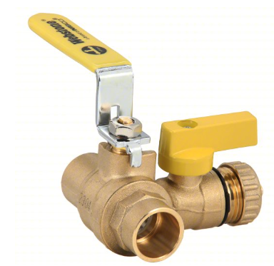
One purge and ball valve, Webstone, shown below.
at the return piping allows you to purge zone by zone.
Simple, clean, user friendly, you get air separation, dirt removal, magnetic particle removal and hydraulic separation form a Sep 4
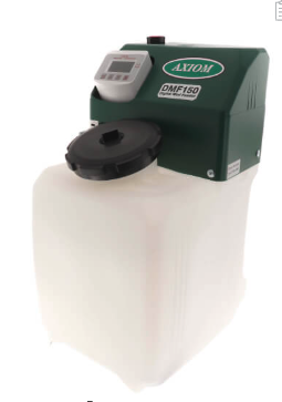
If you are staying with glycol, an Axion fill tank connects at the expansion tank.
Caleffi Idronics are a good source of hydronic knowledge. Written by an engineer for non engineers :) #15 & 19 are a good read for this project.
 Bob "hot rod" Rohr
trainer for Caleffi NA
Living the hydronic dream0 -
normally you would purge it to get it flowing then the air elimination would do the rest.
It could be a little neater but looks to be pretty well installed to someone that knows what they are looking at.
without digging in to the controls my guess would be it is set up primary secondary with a boiler pump that runs whenever the boiler is on, the old part of the system is zoned by zone valves and the add on it zoned with a circulator that only runs when that zone is calling for heat and is controlled off of one of the built in zones built in to that boiler. The zone that is zoned by circulator needs to have a flow check valve which may be part of the circulator.
that boiler should have outdoor reset set up to modulate the swt based on outdoor temp, you will have to tweak the settings to match the actual output of your emitters and heat loss of the house, i think it can be set up with one curve for the zone valve zone and another for the circulator zone.
that boiler really needs a combustion analysis when it is installed at very least.
the end switches on the zone valves should fire the boiler on the zones zoned by zone valve, either buy being paralleled together and connected to the zone valve zone's t-t or x-x on the boiler or by landing on a zone valve controller and that connecting to t-t or x-x on the boiler. It is common for the end switches in zone valves to fail after a few decades so some of the end switches may be bad. The control head is replaceable on those zone valves, newer ones it is a direct replacement, older ones need a kit to convert the valve to have the control head serviceable without opening the system.
0 -
The things that you really are missing are labeling and some system diagrams, I think what you have there is basically a good install, possibly with a few broken parts or a few things that were changed by someone that didn't know what they are doing. I don't think it needs a complete rebuild, just a few tweaks.
0 -
Im almost certain 1” copper comes out of the boiler
Looks to me like it was reduced to a 3/4 air purger, then increased to 1/1/4” on the outlet side of the purger. Not exactly best piping practice if that is the case. Decreasing pipe size increases velocity which lowers the purgers performance a bit, but obviously it has worked😲
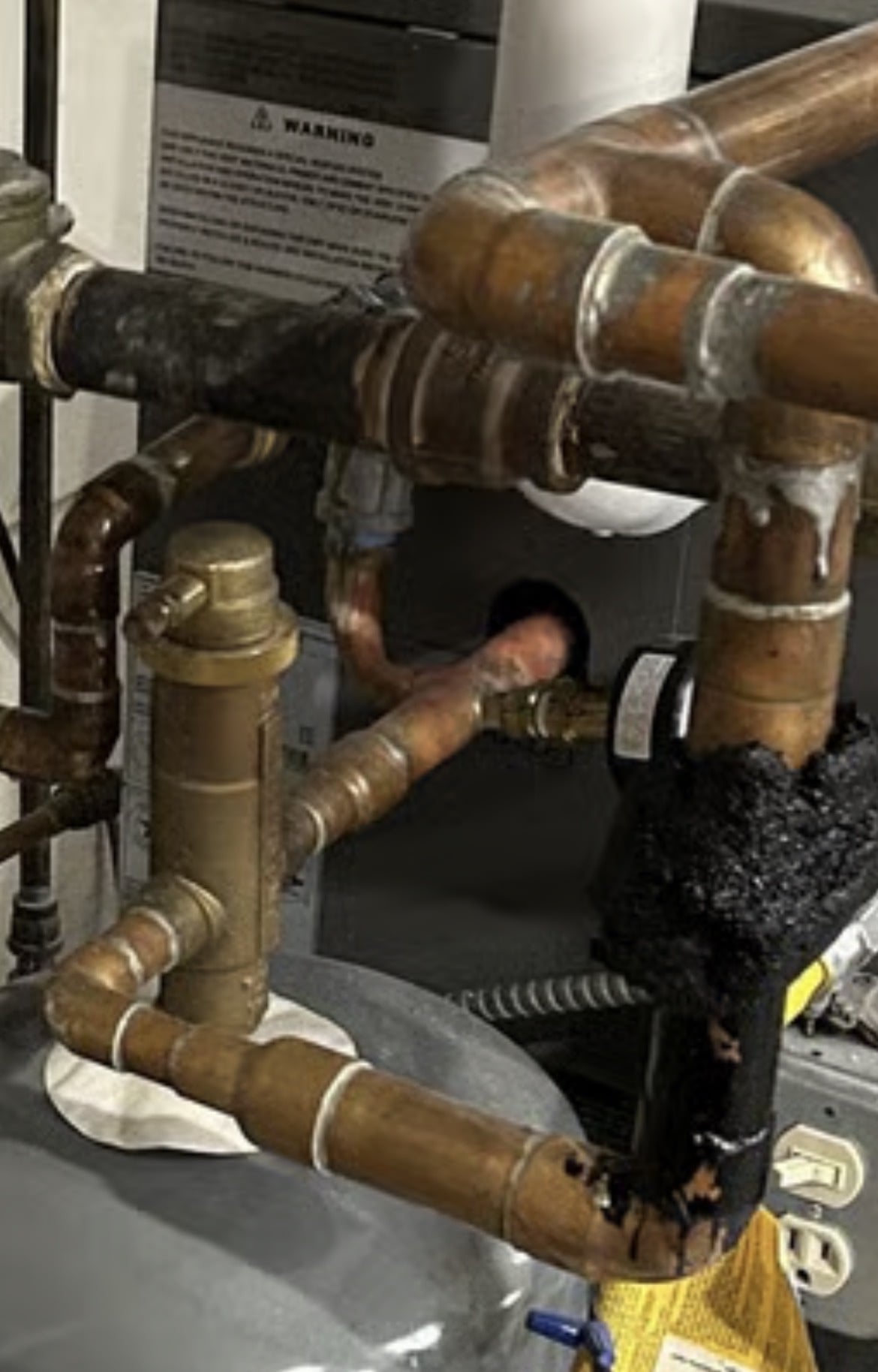
I can’t quite follow a primary secondary piping path, but it may exist?
How do you generate domestic hot water?
What type of heat emitters ?
A one temperature system I assume?
It is not unusual in a post like yours for info to dribble in
The best steps would be a heat load calculation , room by room first.
Select the type of heat emitters
Size them to the heat load based on the temperature you want to run. The lower the better for efficiencies. But fin tube needs hotter supply than radiant floors for example
The select a boiler, number of zones and piping method.
Final steps include cleaning the system by running a hydronic detergent, fill, purge, adjust boiler combustion after and hour or so of running up to design temperature.
Glycol is a last resort in my book, it brings some baggage.
Bob "hot rod" Rohr
trainer for Caleffi NA
Living the hydronic dream0 -
I don't think it is primary-secondary as i look at it more, i'm not 100%sure what is with the 3 circulators. maybe the returns from one group of zone valves is on one circulator and another group on another circulator and they are tied in to 2 different zones on the boiler so one group of zone valves calls one circulator using the pump relays in the boiler and another group of returns calls the other circulator. Kind of a weird way to do it but I guess it is ok if it is wired and configured right in the boiler.
0 -
It looks like it may be using more than one outlet tapping on the boiler but I can't tell from the pictures and intersecting piping. You may have 2x3/4 connections which can move most of the output of your boiler. The boiler also may be much bigger than the connected radiation so maybe it can only put say 60,000 btu/hr in to the house because of the size of the emitters.
I kind of have a feeling that whoever replaced the boiler knew something but less than whoever installed the original system.
0




Categories
- All Categories
- 87.8K THE MAIN WALL
- 3.3K A-C, Heat Pumps & Refrigeration
- 59 Biomass
- 430 Carbon Monoxide Awareness
- 133 Chimneys & Flues
- 2.2K Domestic Hot Water
- 6K Gas Heating
- 124 Geothermal
- 170 Indoor-Air Quality
- 3.8K Oil Heating
- 79 Pipe Deterioration
- 1.1K Plumbing
- 6.7K Radiant Heating
- 396 Solar
- 16.1K Strictly Steam
- 3.5K Thermostats and Controls
- 56 Water Quality
- 51 Industry Classes
- 51 Job Opportunities
- 18 Recall Announcements