Help locating a manual


I'mI'm seriously getting my butt kicked on this one. Searching for any of those part numbers the other one in the upper right hand corner or the ones on the left hand side of the table I cannot come up with anything that actually takes me to a manual.
Comments
-
What type of equipment? What make and model?
All Steamed Up, Inc.
Towson, MD, USA
Steam, Vapor & Hot-Water Heating Specialists
Oil & Gas Burner Service
Consulting0 -
sorry, the pic ddint upload
0 -
 0
0 -
Sadly, the Psychic network is down.
National - U.S. Gas Boiler 45+ Years Old
Steam 300 SQ. FT. - EDR 347
One Pipe System1 -
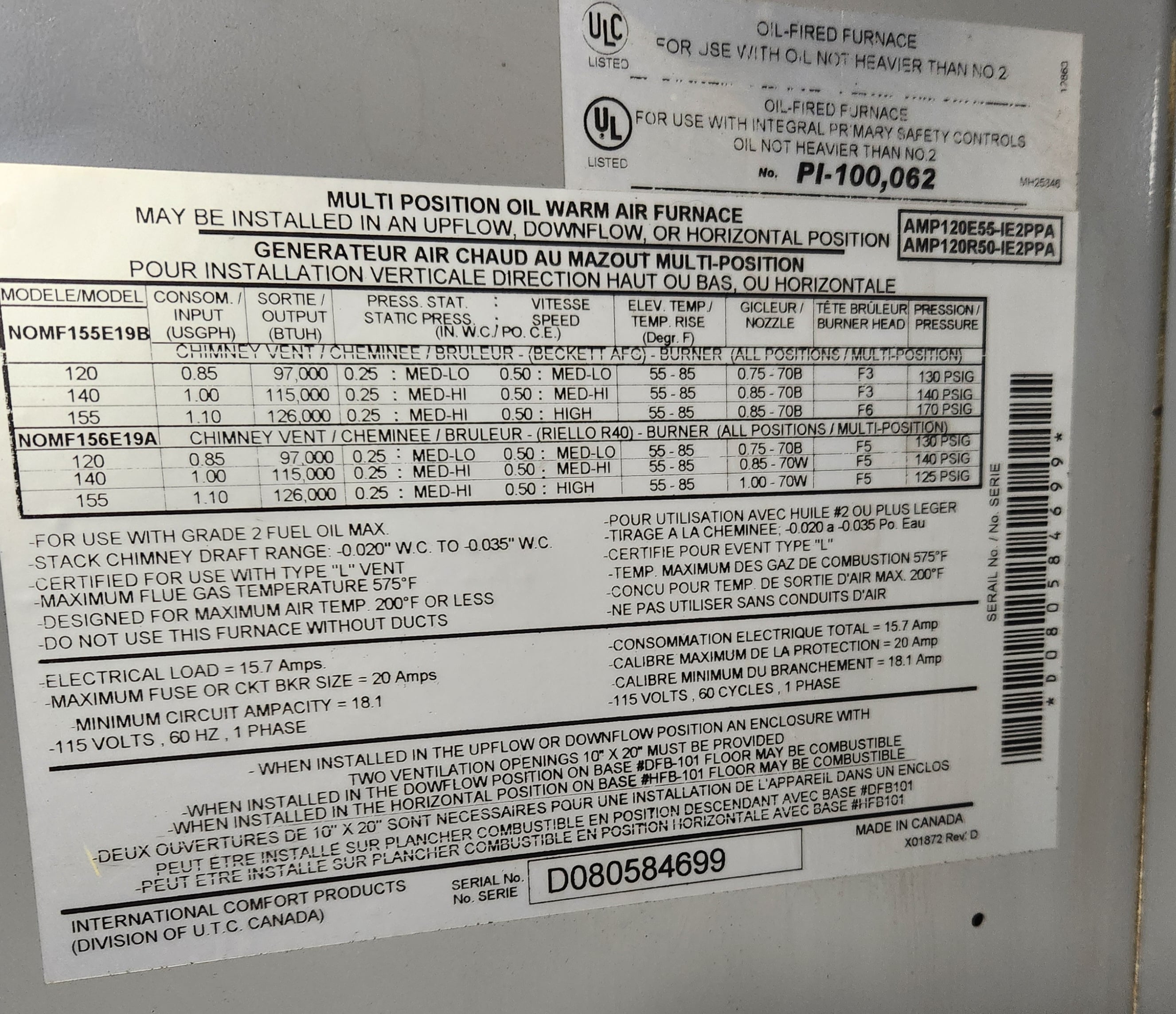
looks like it is heil which looks like it got acquired by carrier
that instruction sheet looks like it is throwing everything out there and letting you guess what applies to your installation
i think there should be a ratings plate somewhere, those look like generic labels for the series
0 -
I looked everywhere for better information. It sees that with furnaces the manufactures are not so proud of their product. No brand label on the product
0 -
Seems there is a few possibly similar manuals. What are you trying to figure out?
 National - U.S. Gas Boiler 45+ Years Old
Steam 300 SQ. FT. - EDR 347
One Pipe System0 -
wiring mostly, it has a power vent and the startup sequence doesn't seem to be right:
Call for Heat
Valve on delay starts
Power vent starts
burner motor starts (after vent is proven)
the customer is experiencing random "No Ignition" Errors (Honeywell R7284U primary)
While I was there, I did see one time that the the TFI ended before the draft was proven/burner motor start. resulting in "No Ignition"
This seems out of sequence to me, the TFI should should start when the burner motor starts + prepurge time, In my mind.
The The "motor" lead from the primary feeds goes up to the power vent as expected. however the returning wire from the power vent comes into the primary junction box and connects a wire that runs out to the air handler. then another wire from the air handler come bac into the box and connects to the wire to the motor.
L1 and Limit are powered all the time, jumpered together Burner is started by TT
I hope this makes sense
0 -
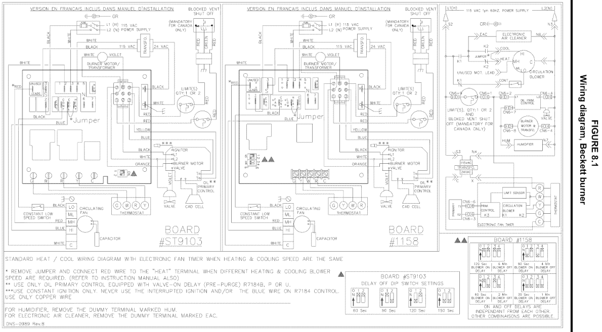
There are different diagrams depending on the burner, I don't think they include the wiring for the power vent, you would have to look at the power vent manual. If it is wired to be a race between the power vent proving and the TFI ending and the power vent proving is slower than when new I could see it being intermittent.
 National - U.S. Gas Boiler 45+ Years Old
Steam 300 SQ. FT. - EDR 347
One Pipe System1 -
1-800-458-6650 ICP customer service
Give them a call why struggle.
1 -
The Furnace wiring diagram was not on the back side of one of the covers ?
National - U.S. Gas Boiler 45+ Years Old
Steam 300 SQ. FT. - EDR 347
One Pipe System0 -
I ran into something similar some years ago. The fix was to not let power get to the burner primary unless/until the draft proving switch on the power venter had closed. In this case, it might be best to have whatever now operates TT on the R7284 operate a relay instead which would start the PV. Question- is the air proving switch on the PV a "dry contact" a.k.a. a switch that gets its power from somewhere else, or does it just send 120V back to the burner to start the motor?
All Steamed Up, Inc.
Towson, MD, USA
Steam, Vapor & Hot-Water Heating Specialists
Oil & Gas Burner Service
Consulting

 4
4 -
Looking at the manual (Tjerlund SS-2) it can be configured for dry contact, low or high voltage thermostats
Could I bring TT from the thermostat over to the dry contact. Jumper TT on the primary and then use the output from the power vent to turn on the to power the limit on the burner.
I'm sitting the dentist office right now. But I know this would require a bit more reading and some configuration change in the power vent control
0 -
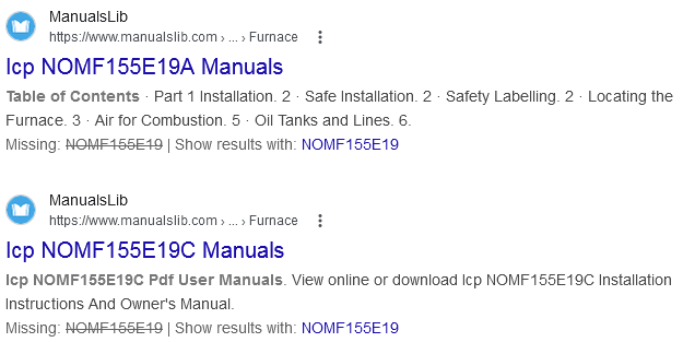
This is your manual: manualslib.com ICP oil furnace You may need to log on to manualslib.com to download it.
When using any oil furnace with a sidewall vent system such as a Field Controls or Tjernlund power venter, the safe way to connect the power venter is to make sure the vent motor is operating with a pressure switch that operates a set of dry contacts. Those contacts interrupt the orange wire from the oil burner primary control to the oil burner motor. This will cause the oil burner primary control to shut down on safety reset if something is not operating properly.
This can cause confusion when trying to diagnose a flame failure problem in an oil burner with a power venter connected to the system properly.
You need to look at the wiring logic to be sure it is installed properly, and then look at the startup sequence to see what is not operating correctly. It could be a blocked vent, a failed vent motor, a bad pressure switch, or a blocked pressure sensor tube.
Those things have nothing to do with the oil burner or furnace wiring. They are symptoms of a vent system failure, and the oil burner is simply functioning as it should as a result of that vent failure.
Edward Young Retired
After you make that expensive repair and you still have the same problem, What will you check next?
1 -
Unfortunately not
0 -
@EdTheHeaterMan , that's one hookup I've seen. I think what you're saying is that if the burner is energized but the power venter doesn't prove air movement, the burner motor doesn't start and the burner primary locks out, right?
The other way is for the power venter to energize first, and wire the proving switch as a dry contact that closes the thermostat terminals on the burner, boiler or furnace. With this setup, if the power venter doesn't prove air movement, the burner/boiler/furnace would simply not start. IMHO this is easier to troubleshoot.
All Steamed Up, Inc.
Towson, MD, USA
Steam, Vapor & Hot-Water Heating Specialists
Oil & Gas Burner Service
Consulting 1
1 -
I agree to a point @Steamhead the trouble with that wiring logic is that any Tom, Rick or Harry with a jumper wire can get the heat to run my doing what the vent safety switch is not doing. That is why the manufacturer requires the orange motor wire to be interrupted. This makes the simple fix that bypasses the side wall vent more difficult. You got to know what you are doing to bypass the vent safety design. If you can figure that out then you can also figure out why the vent safety switch is the reason for the failure and fix that problem also.
Where this gets more complicated with the ICP furnace is the oil burner motor is already interupted when using the fan timer like the ST9103. The primary control for the burner (like the Carlin 70200 or Honeywell R7184U) has the Orange wire from the primary goes to the #7 pin on the ST9103 to signal the control logic that the burner is running. The ST9103 then powers the burner motor and ignition thru pin #8.
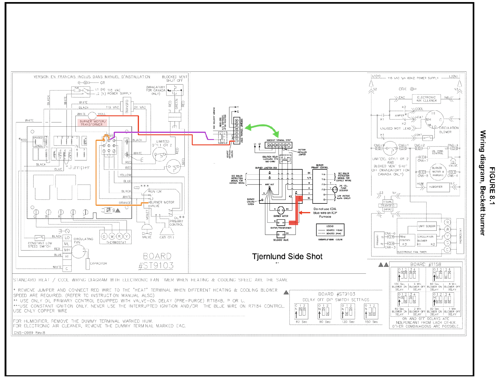
So if you use the #8 pin to break the motor thru the side wall vent control like shown in this diagram, or if you use the Orange from the primary control > to the side wall vent > then the the #7 pin, either way you are adding another stem into the sequence of operation that can take up some extra time of the primary control's trial for ignition timing. So it is important to make sure the pressure switch tubing is clear and that the fan blades are clean, because both of those getting debris build up from normal operation, may cause the problem that @Robert_H has discovered on this project. It may be something else but That is where I would start whenever I have an issue with a Flame Failure or No Ignition fault when there is any side wall vent system involved.
To explain the diagram parts that are at play here:
- Call for heat
- ST9103 Molex pins #3 and 6 call for heat at the primary control
- Orange wire gets 120 V. and powers up the #7 Pin of the ST9103 Molex, and that provides 120 v. to the #8 pin.
- #8 Pin on the ST9103 powers the Side Wall vent
- Side wall vent then sends 120 v. to the burner motor and ignition.
- Burner motor and ignition start
- Hopefully this all happens before the valve opens and the primary control then powers the valve and the flame is ignited and the flame sensor allows the burner to operate for the full heating cycle.
- Burner goes off by high limit or by a satisfied thermostat and is ready to start again on the next call.
What can go wrong here is
- The ST9103 can be a problem as they often do even without side wall vents
- The power vent can take more time that normal to send poser top the motor
- which allows the valve to open before the burner motor starts causing dirty ignition
- which keeps the burner from operating during the trial for ignition
- Primary control can fail as sometimes happens on systems even without side wall vents
Edward Young Retired
After you make that expensive repair and you still have the same problem, What will you check next?
1 -
@Robert_H asked "Looking at the manual (Tjerlund SS-2) it can be configured for dry contact, low or high voltage thermostats
Could I bring TT from the thermostat over to the dry contact. Jumper TT on the primary and then use the output from the power vent to turn on the to power the limit on the burner.
I'm sitting the dentist office right now. But I know this would require a bit more reading and some configuration change in the power vent control"
Unfortunatily if you have the ST9103 fan timer for oil burners then that would be ill advised. there is some basic electronic logic in that ST9103 Fan Timer that would be interrupted if you did that. It might work but it may not. and it might work for some short time but fail over time reauiring a new ST91o3 fan timer control board. I'm sure you don't want that on your hands.
And the dentist office is not the best place for thinking about heating problems, It can leave with a hole to fill, and the filling ain't vanilla or chocolate, besides it was not ever tooth-hurty (02:30) when you were there, it looks close to 9 o'clock.

Edward Young Retired
After you make that expensive repair and you still have the same problem, What will you check next?
0 -
They could do the same thing by moving the orange motor wire to the orange lead going to the ST9103. Both are stupid moves, and we all know you can't fix stupid.
All Steamed Up, Inc.
Towson, MD, USA
Steam, Vapor & Hot-Water Heating Specialists
Oil & Gas Burner Service
Consulting0 -
But Duct Tape can make it quiter

Edward Young Retired
After you make that expensive repair and you still have the same problem, What will you check next?
1 -
I went to sleep thinking about it, woke up thinking about it, and got reprimanded for not paying attention to my wife thinking about it :D
and thank you for pointing out the issue with the ST9103 fan timer (another rabit hole to run down.)
0 -
Seems like the mfg. wants a lockout if the power vent fails or does not prove. That is the safe way but can be a nuisance.
On the other hand, starting the burner through the power vent proving switch (air flow) can give you a situation where the burner is starting and stopping on a chattering air flow switch if not wired to lock out.
But then power venters are a nuisance anyhow.
1 -
0
-
Ok, I did crayola time in the van today between stops and came up with this. I like yours better and really appreciate the time you took to explain this, especially the clarification of the sequence an the problems RE the fan control and the PV. I am studying!!!
 0
0 -
One other common fault in the side wall vent control that break the motor connection between the primary and the motor is that in some cases the pressure of the flame ignition causes the sidewall vent pressure switch to open which stops the oil burner motor. Once the flame is extinguished the pressure in the vent system drops and the pressure switch proves and the contacts close. That causes the ignition of the flame to pressurize the vent system and opens the pressure switch again. This goes on for 30 seconds or longer on a primary control with a 15 second safety timing. Eventually the safety trips on the R7184 or even the analogue R8184 primary controls.
If you ever come across a short cycle that has the flame ON then OFF then ON then OFF…. in a 2 to 4 second cycle, then your vent proving pressure switch is the place to start looking.
Edward Young Retired
After you make that expensive repair and you still have the same problem, What will you check next?
0


Categories
- All Categories
- 87.6K THE MAIN WALL
- 3.3K A-C, Heat Pumps & Refrigeration
- 59 Biomass
- 430 Carbon Monoxide Awareness
- 124 Chimneys & Flues
- 2.2K Domestic Hot Water
- 5.9K Gas Heating
- 120 Geothermal
- 168 Indoor-Air Quality
- 3.8K Oil Heating
- 78 Pipe Deterioration
- 1K Plumbing
- 6.6K Radiant Heating
- 394 Solar
- 16K Strictly Steam
- 3.5K Thermostats and Controls
- 56 Water Quality
- 51 Industry Classes
- 50 Job Opportunities
- 18 Recall Announcements