Radiant header theory

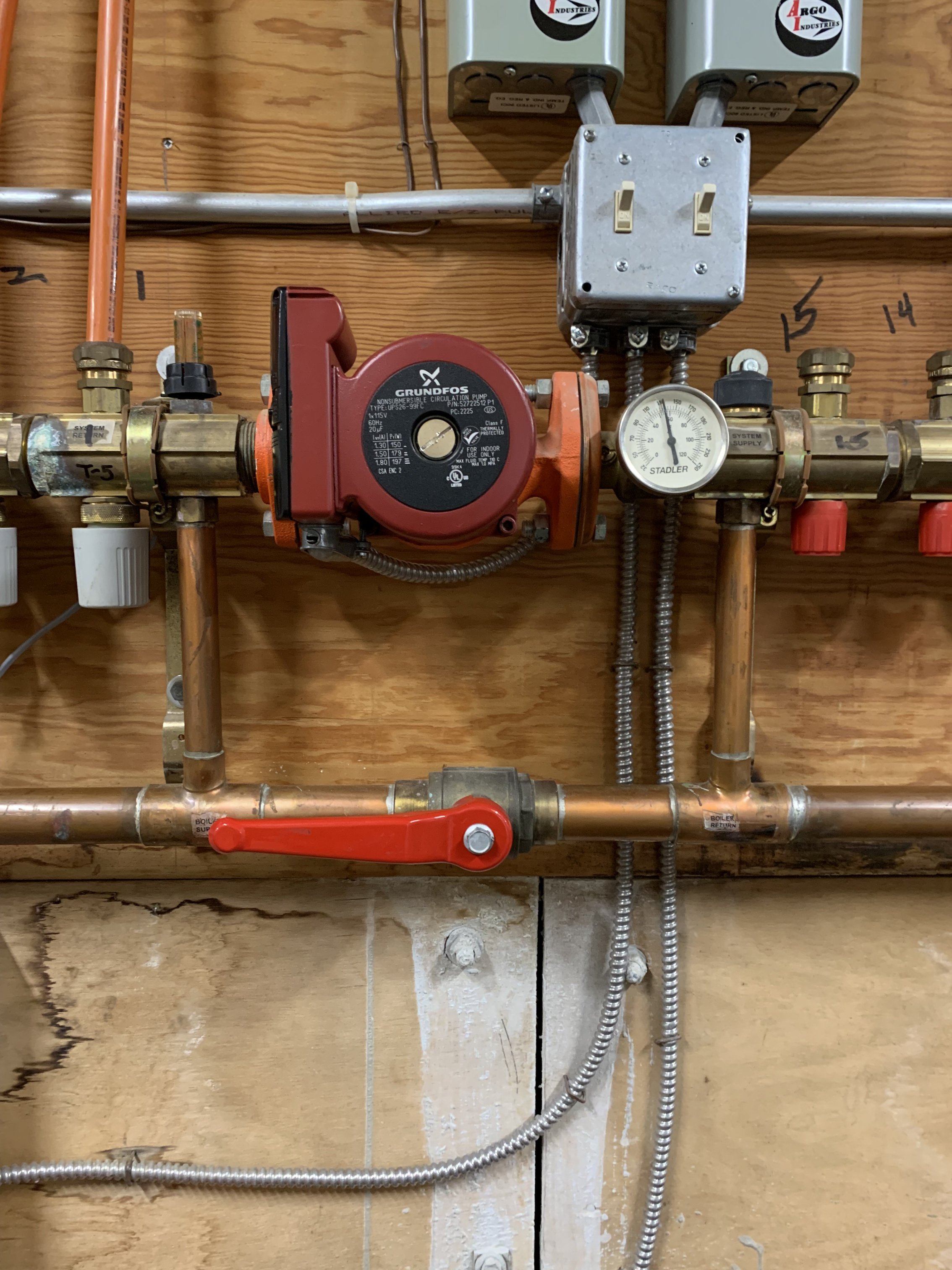
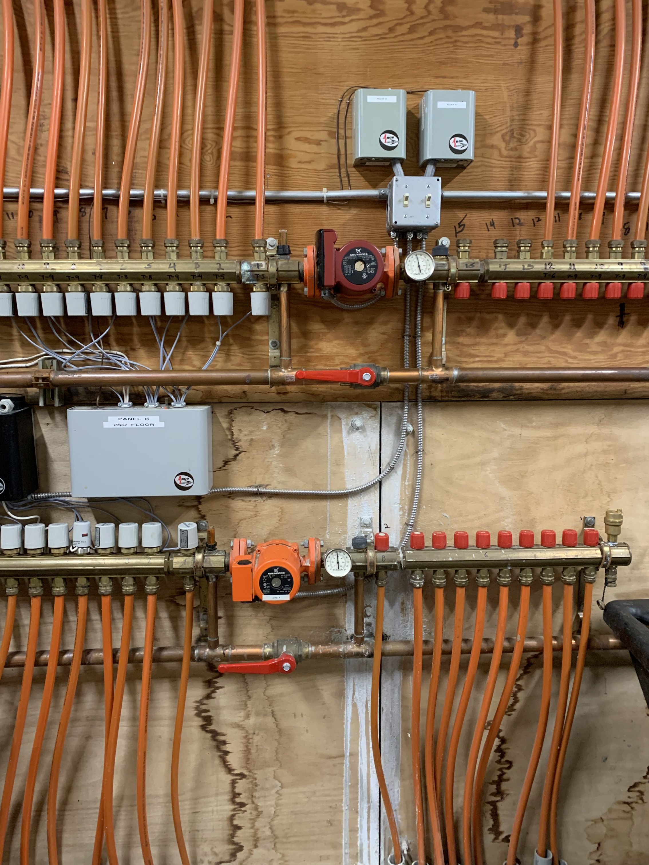
What is the operational theory behind this configuration? The horizontal pipe below the circulator is a secondary loop flowing left to right with mixed water via Viessmann supply mixer. The left hand vertical branch into the manifold is marked boiler supply and the right side boiler return. Supply side has a Stadler flow control wide open and the return has the grey cap mixer you see on the old ST headers. There’s an identical header below this one set exactly the same. The system was installed around 2004, I think. I don’t know this configuration so I can’t adjust to a higher water temp for the upper manifold during sub zero temperatures. Works great at 15 degrees F and above. Any radiant gurus seen this? I’m a private school maintenance guy now with 30 years of past residential experience but haven’t seen this style. Mostly the old ST headers type.
Comments
-
 0
0 -
The original design probably had a flow rate requirement that you set on that flow meter above the left vertical pipe. That clear plastic indicator probably rotates with the black knurled nut to adjust flow.
So a % of hot supply from the lower left horizontal blended with return from the upper left manifold. The temperature gauge would allow you to see the mixed or blended temperature.
So the design may have indicted gpm to set that flow meter, temperature requirement and probably gpm per loop.
The black kob on the right vertical allow you to shut off that port. With the cap off or loosened, it is open. Acrew the cap down closes that port. Sometimes the flow balance is done with that cap, if the clear plastic meter doesn't adjust?
Looks like you are sending about 150° to the system. Is this a infloor concrete system? , that would be fairly hot supply for a slab. The type of tube installation, load, floor coverings determine what SWT is required.
It does seem odd to have a mix system at the boiler and this mix setup at the manifolds. Maybe a pic of the entire boiler piping might explain better what the intent was.
This is my best guess, anyway.
Is the system working properly? If anything that supply may be a bit high.
Bob "hot rod" Rohr
trainer for Caleffi NA
Living the hydronic dream0 -
That floor temp is high because I played with a flow rate for the supply loop and it hadn’t calmed down yet. It usually sits at 120. The mix actuator is located in a boiler room some 40 feet and a crawl space away. I’m hoping that I can tweak one header station to 130-140 in zero outdoor conditions and keep the other at 120 because it has less infiltration and can maintain. Not ideal but it’s not often that it would need to happen. I think maybe this setup isn’t very flexible but I hope to understand the design better so I can make good decisions on what to do next.
0 -
got a pic of the Viessmann mixer? Those are usually set on an outdoor reset curve, so the temperature to the manifolds should be vary depending on outdoor temperature. If that was dialed in the temperature should never get to hot at the manifolds.
Bob "hot rod" Rohr
trainer for Caleffi NA
Living the hydronic dream 1
1 -
Well it turns out that the Viessmann mixer is controlled by a Trimatic MC with all its Viessmann nuances and the really big problem is that the mixed loop (secondary) pump doesn’t stay running during a call for heat so it may be on a timed program and I’m going to have to learn about the Trimatic control. Thanks for the input.
0 -
here are some documents about that control. There may be a couple of different ways the mixing valve was set up
1


Categories
- All Categories
- 87.6K THE MAIN WALL
- 3.3K A-C, Heat Pumps & Refrigeration
- 59 Biomass
- 429 Carbon Monoxide Awareness
- 124 Chimneys & Flues
- 2.2K Domestic Hot Water
- 5.9K Gas Heating
- 119 Geothermal
- 168 Indoor-Air Quality
- 3.8K Oil Heating
- 78 Pipe Deterioration
- 1K Plumbing
- 6.6K Radiant Heating
- 394 Solar
- 16K Strictly Steam
- 3.5K Thermostats and Controls
- 56 Water Quality
- 51 Industry Classes
- 50 Job Opportunities
- 18 Recall Announcements