HOWTO: Fully restoring an Illinois Vapor Heat Retainor (Heat Retainer) (Air Eliminator) System

Intro
We'll be going through full restoration of a 1929 vacuum/vapor heating system, including a detailed photographic teardown of an Illinois Heat Retainor - Browne Patent - No. 1450-245
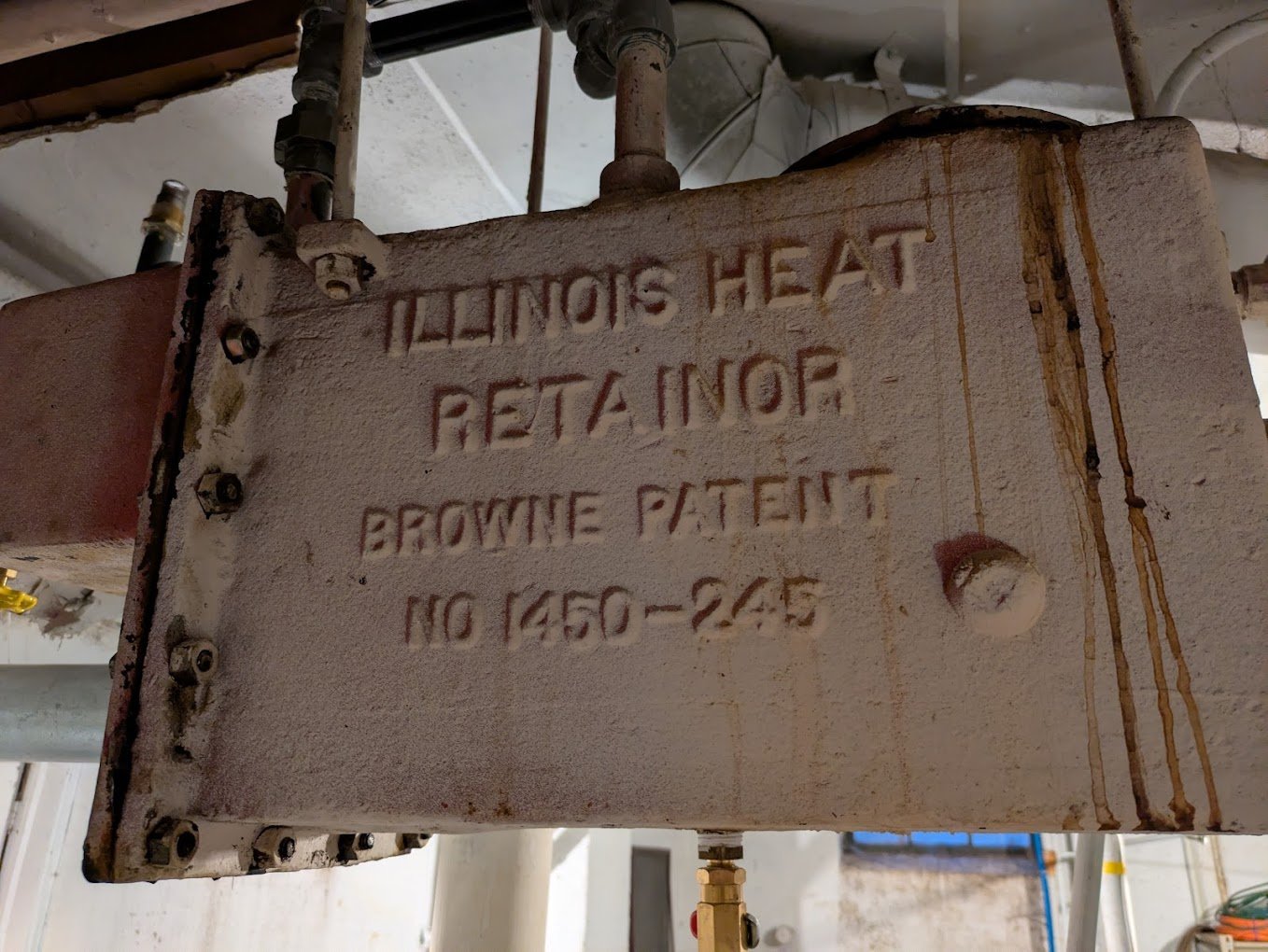
Yup. They decided to spell it "Retainor." So that's the spelling I'll be using throughout.
Along the way, we'll talk though some of the various systems problems I encountered over the past few years, along with how I fixed them.
I'll also present two interesting mysteries that I hope will test your mettle, if you so choose.
You might want to find a comfortable chair and crack open a beer for this one. It's gonna ramble quite a bit, but it does tell a nice story.
Or at least. I'd like to think so.

Comments
-
As found at time of purchase (2021)
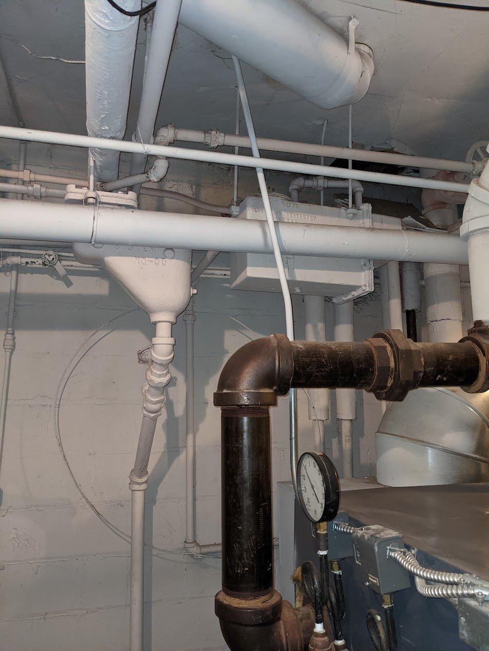
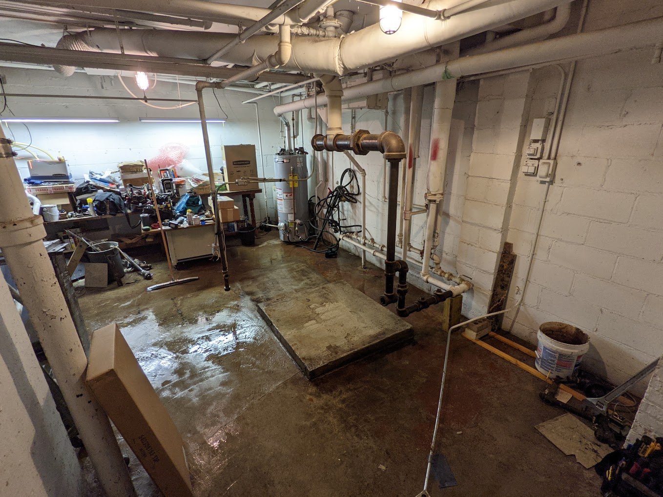
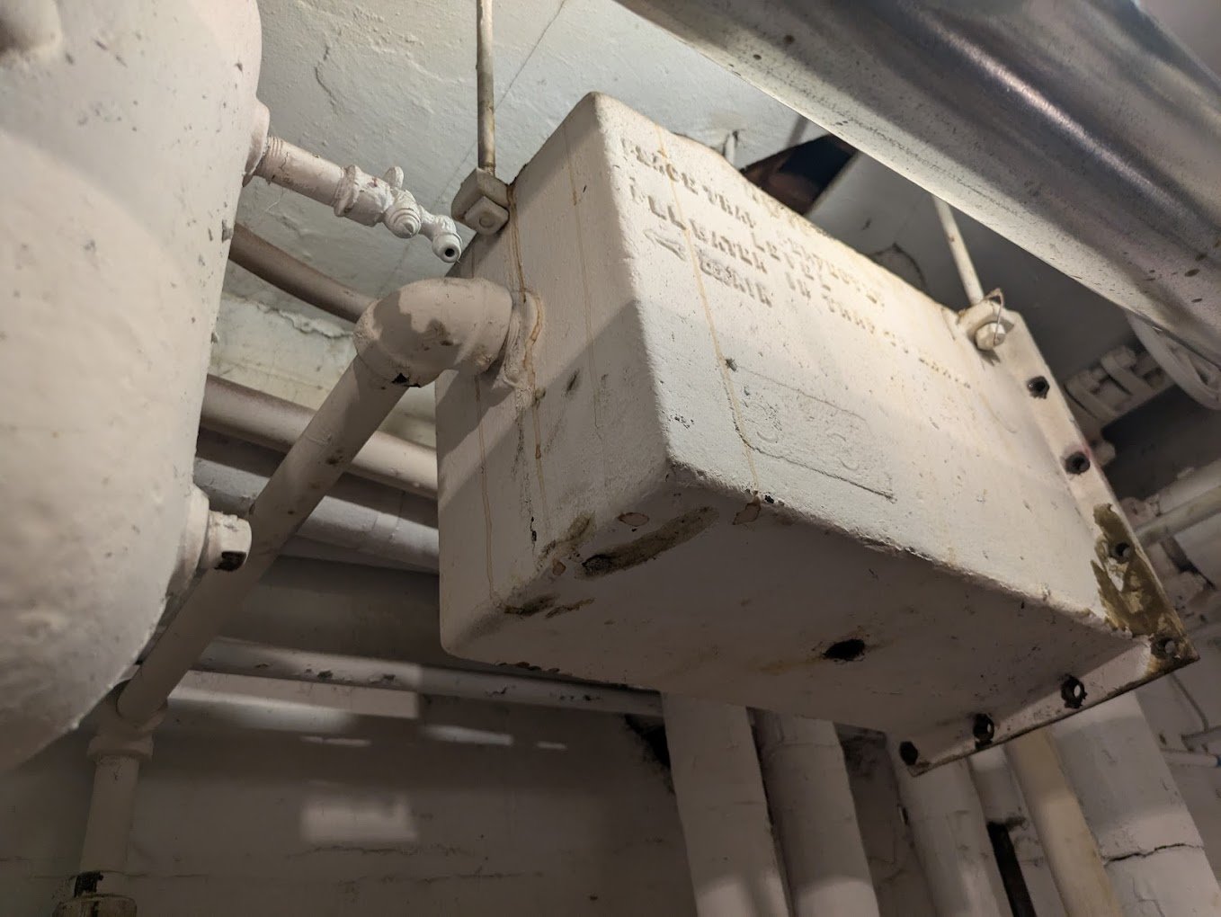
Two pipe vapor/vacuum system. Upper left ham-shaped thing is the return trap which, as found, didn't operate. Upper right box is the main vent which also does not vent at all. When built in 1929 this device was called the "Heat Retainor" — they called it that because it "retained" the system's ability to deliver steam (and therefore "heat") to the radiators, once the coal burned down and the water fell below 212 degrees.
The partially hidden casting text on this side says: "NOTE: PLACE TRAP PERFECTLY LEVEL. FILL WATER IN TRAP TO DRAIN" It was not "perfectly" level but that never ended up mattering. It doesn't actually seem to be all that sensitive to leveling.
But really, it's just a main vent that will seal up and allow the system to pull vacuum. In later years they started calling it an "Air Eliminator" which made a lot more sense. The problem is, it's not doing that. It doesn't vent, at all, and therefore the whole system now has has no venting of any kind. There is, inexplicably, a standard one-pipe radiator vent attached to a single radiator on the second floor. This one radiator vent is not effective, not even for the radiator it's attached to.
Previous homeowner is operating one 1500W oil-filled-electric-radiator in every single room of the house. This is a 5000 sq ft, 5 bed, 5 bath house. I idly wonder whether this explains the surprisingly modern 200 Amp main panel.
Perhaps it's the other way around. Perhaps the new panel and modern romex explains how the house is still standing, instead of being a messy pile of former-house that sits inside a still-smoldering basement foundation.
Anyhow.
Despite the fact that all heating for the house is currently being done electrically, the previous homeowner also chose to run the steam heat too. Perhaps they thought a more naïve buyer might not notice it wasn't doing anything.
So steam is on, and is being run at 15 FREAKING PSI. (As one does.) Boiler steams to max possible pressure, then cycles on pressure. Given no venting, the system is airlocked and delivers no heat to any radiators in any way. A steam main cutoff valve that is 8 feet from the boiler can be comfortably touched on the valve case with bare hands.
The whole system is air-locked and this includes the single oddly vented radiator upstairs. The vent blows air hard enough to whistle, but even so the radiator doesn't get hot.
Obscene levels of excess pressure have blown out the section to section seals of a boiler that appears to be less than 10 years old, and from all the leaks, the bottom of the cast iron heat exchangers and all the burners are all rusted badly.
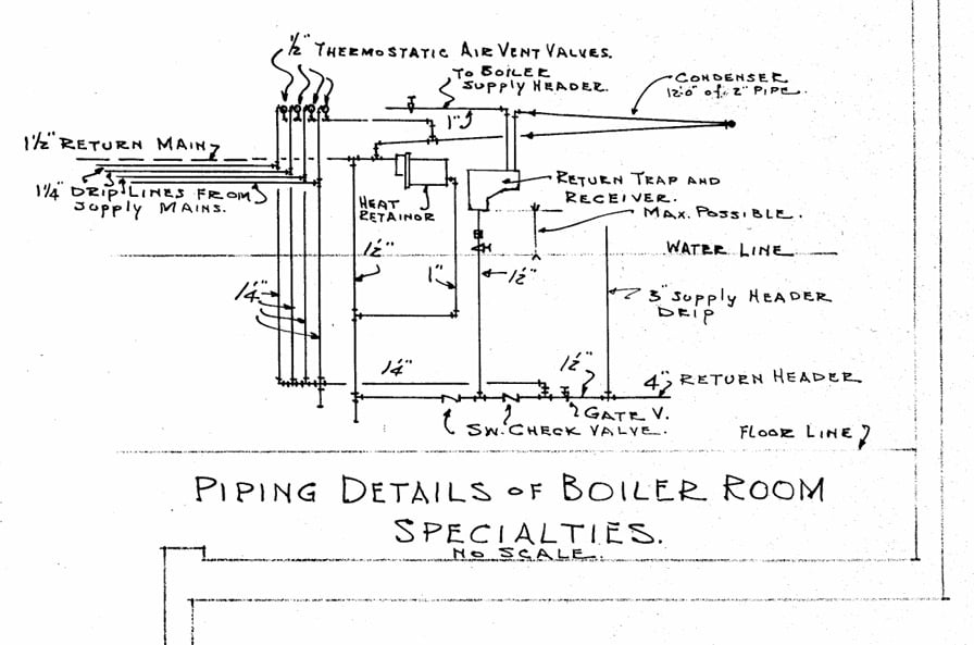
The house comes with original blueprints. Not blue-line prints. Beautiful original cyanotypes. I scanned them and converted to black and white to make them a little easier to read and reference. They Include a full as-built heating schematic in a beautful 2.5D format that shows basement piping, and risers, and first and second floor radiators, all on one page, and includes EDR for each individual radiator unit, and a detail of the boiler room piping.
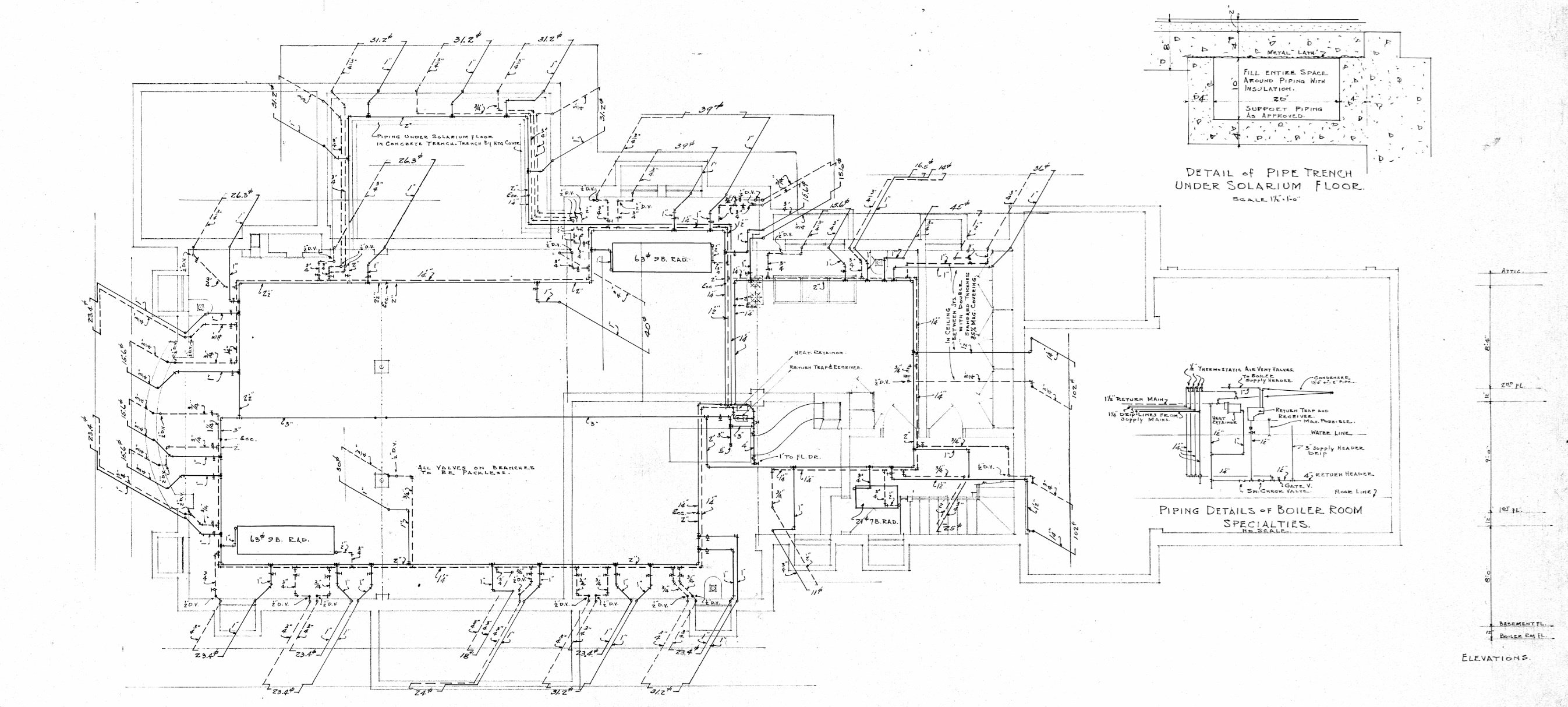

With the original blueprints plus some corrections for changes that occurred in the house through the years, it brings the tally to 932 EDR, demanding 223,680 BTUH.
Side note: The currently installed Weil-McLain LGB-8 boiler provides 910,000 BTUH.
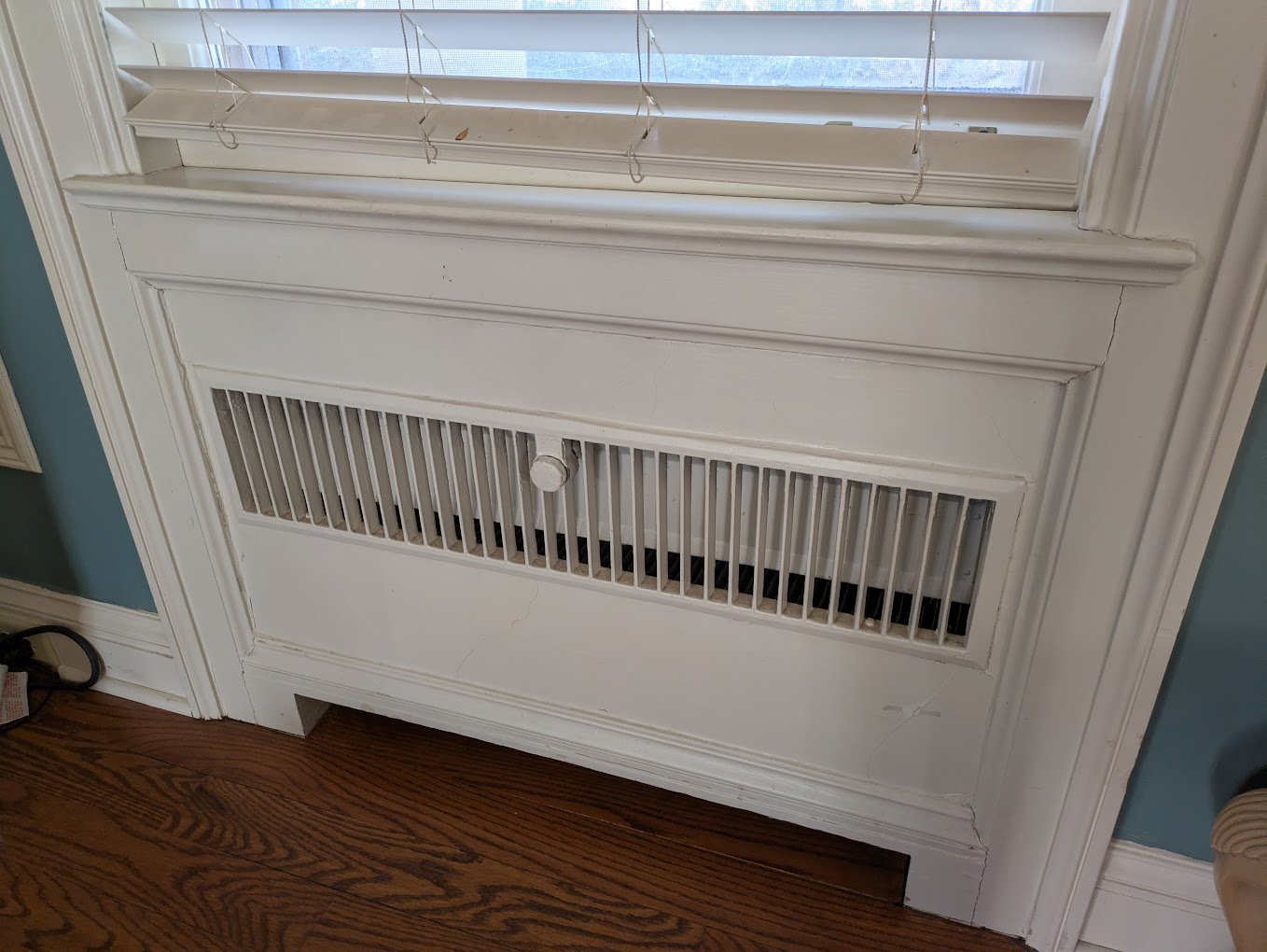
All house radiators are in-wall fin units with an air damper. By turning the knob, you open or close the damper. The radiator will condense only as much steam as there is air to carry the heat away. The whole system sits flush inside the wall. Beautiful.
Outliers: A few of the bathrooms have fin units radiators wrapped in a metal box housing under their sinks, mounted behind the sink column in front of the bathroom tile. There is a single standard cast iron radiator in the front entryway. An upstairs bathroom renovation happened in the '60s and it has a more traditional modern radiator unit with a metal shroud like you see in elementary schools from the '60s. The basement was built as a year-round laundry complete with (indoor!) clotheslines and has three very large (63 EDR each!) horizontally mounted overhead cast iron radiators.
0 -
Step one - Replace boiler, get basic venting.
Bought Dan's book and read it cover to cover several times.
Found some outstanding docs about the Illinois Engineering Heat Retainor and return trap and in-wall radiators on the Internet Archive:
Illinois thermo modulating system of vapor heating, Illinois Engineering Co., Chicago, New York, for apartments, hospitals, hotels, schools, residences : Vapor system details, Bulletin Number 22. : Illinois Engineering Company. : Free Download, Borrow, and Streaming : Internet ArchiveComputed the EDR and decided the boiler was WAY too big.
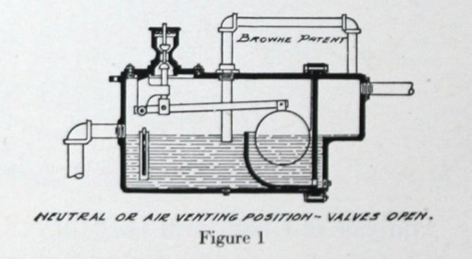
Negotiated for half the price of the new boiler to be paid by the seller. Got a decent local company, talked through the challenges of getting it vented. Gave them the docs on the heat retainor. I won't go through the details, the PDF does an outstanding job explaining. Big thing is, here's what it looks like inside. After passing the crossover traps, condensate and air (but no steam) enters in the pipe at the right, air goes throught the horizontal pipe at the top, and bubbles down through the water into the left chamber, then goes out the top, while condensate goes out the left and down to the boiler. Along the way there's a really neat design involving the float and the water levels in the two compartments that makes it so the trap should close tight, if there's vacuum.
Except my air vent doesn't vent.

So the heating contractor came up with a plan to entirely bypass the retainor as an air vent — They would pull the (not shown in the illustration but obviously necessary) union in that horizontal pipe outside the box on the top, re-pipe to add a tee, and add a horizontal pipe with a swing check valve. And at the end of the pipe, add a Hoffman #75 for an air vent. Air goes in, up, though the tee, through the vent, and out.
Talked about opening and bringing the heat retiainor back to its correct function as a main vent. "We've opened those things before, all you'll find inside is a pile of rusted fragments, and it might not go back together. We won't risk that, We're just going to bypass it."
They also refused to budge on reducing the size of the boiler, not believing that a homeowner knew how to compute EDR. "That boiler that's there is enough to heat the house, we're not going to go smaller and install something that might not work. We're already absorbing a lot of risk on this job given the unknown state of your air vent."
Should have pushed harder, but also I saw their point about being afraid to change too much at once. Even though I knew I was right. Live and learn.
Replaced the boiler. Here's a picture mid-install, with with one or two parts still missing.
First problem: Surging.
They did absolutely nothing to skim the boiler (not that anyone seems to these days) so I had crazy surging. Spent a week of an hour or two at a time doing the skimming myself. There is no floor drain in this room, only a "sump pit" directly into the dirt below the foundation, that will absorb only as much water as well packed earth is willing to accept.
I concluded that I did not find this process to be particularly enjoyable.
Second problem: Working heat, but no vacuum.
Hmmmm. Turns out, a swing check valve for water, when installed in a pipe full of air, does not seal. Replaced the #75 with a #76. Still no vacuum.
Along the way, something in the air eliminator had also changed. It now vents full time and won't seal. (See Bonus round questions below.) I wrapped the holes in the vent cap at the top with layers of electrical tape and plastic sheeting. Got vacuum. My hack mostly sealed the problem. It would pull vacuum to negative 11 PSI when the system shut down and the steam condensed, but that would bleed back up to ambient pressure over about 3 hours or so. It would still had decent amount of vacuum left by the time the next cycle would start.
Third problem: Venting through a single #75 was painfully slow.
Added another tee to the venting tree and added a Kadont Johnson Vacuum Breaker 24A77600 in parallel to the #76 (https://fluidhandling.kadant.com/files/58/Vacuum-Breakers/588/Vacuum-Breakers-Brochure.pdf)
A 1" model is outside tapped at 1" and inside tapped at 3/4". This means you can install it inside out, and then it becomes a vacuum holder instead of a vacuum breaker. It will vent 20 CFM at 2.5 InHg and 40CFM at 12 InHg.
Great product, love it. It's a stainless steel ball in a cage, sitting on a rubber gasket. Vented a lot better.
If you're trying to get vacuum working, for less than $100 off eBay, go buy one of these.
Since the vent is downstream of the crossover steam vents at the end of the main, it should never actually see steam, and I found that that largely held true. It vented a small amount of vapor style steam from what flashed back to steam after passing the traps, not enough for it to be any problem.
So with this, the overall system was was better but it was still somewhat slow. With the main vent capacity from the Kadont Jonhson unit, I now had the feeling that the four Illinois 1G crossover traps were the limiting factor. Given their placement (impossible to access without removing the boiler flue and a lot of overhead stuff), I suspected the bellows elements in them had never been serviced since the day they were installed.
That's a problem for Future Homer. Boy, I don't envy that guy.
Fourth problem: WAY too much heat from the 3:1 oversized boiler. Short cycling.
LGB-8 has a 2-stage valve. Added a Honeywell microswitch vaporstat. Worked like ****. cut-in and cut-out was all over the place, off by as much as 6 oz, even from one run to the next, with no other changes. What a piece of crap. Replaced it with an eBay-sourced Honeywell mercury vaporstat that worked flawlessly. Ran the system at 16 oz cut-out, with the dual-stage set to 2 oz.
Adjusted the dual stage down criminally low. Clocked it at 360kBTU.
Label on the boiler says not to go below 720k. I'm… hoping? that really means, "the high rate shouldn't be less than 720". Running at 360 is probably pretty fuel inefficient, underfired that much, but short cycling is supposed also to be inefficient too. What's better? I dunno. Some day I'll experiment and time how much more or less gas I use, if I turn up the burner higher and make it so it has to short cycle instead.
I also had problems with water hammer at high rates (more notes below), but at 360k BTU, I sit on the edge of vapor steam, and the lower steam production rate helps save me from the hammer.
I also thought about updraft. Maybe 360 might not be enough heat to overcome a very cold downdraft? But I always get a good 5 minute run of high rate heat, before it cuts down to 360kBTU, and once it's already going, 360 is definitely enough to maintain a proper updraft once it's already been started by the high-rate intro period.
I also tried running it at 360 full time, and never letting high rate happen at all. No good. I have a couple radiators upstairs with horizontal runs of supply and return pipes. Somewhere there must be a low spot. If the system doesn't see at least 4 oz of pressure every now and then, there's a sag that fills up with water and air-locks. 4 oz is enough to push the water out gently, without inducing hammer.
System works, more or less.
I left the system that way for a few years.
0 -
Bonus round #1: Why does the heat retainor now vent full time?
I said that "something changed" in the air vent. What is it? If you'd like to participate in this week's game of "think like The Dead Men", then go read the PDF linked above that explains all the details about how it works, and then think about what we've done, and go see if you can figure out why it is now stuck in the always-vented condition. It's a nice puzzle. Two hints below if you get stuck, then the answer.
Hint 1: The float is now always in the neutral position. Why?
Hint 2: What causes the water level to move up and down? Why isn't it doing that now?
Answer:
The pipe at the top outside the box is a one-way air valve because of the water seal inside the box. The right side compartment is supposed to be sealed. By adding the air vent to the pipe outside the box, we have now broken the seal and vented the right side compartment. Therefore the water level in the two halves of the box will equalize, the float is always neutral, and the box is permanently stuck thinking it should be in its "venting" operating position.
0 -
Step 2. Summer 2025 - Fix the heat retainor for good
Started looking at accessing the retainor from the top. There's a circular plate that contains the actual vent itself, and this round plate also doubles as the mount for the float valve assembly, inside the unit.
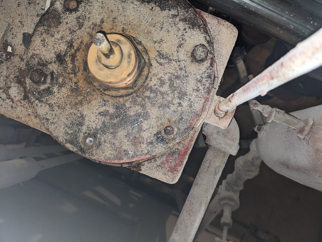
Six bolts, all rusted in place. 2 came out, 2 sheared, and 2 had already sheared by someone long before me, and were left in place broken, so that no one would notice.
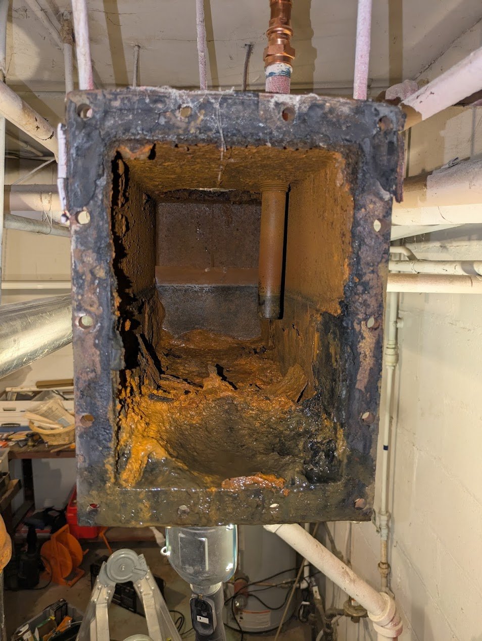
Can't remove the overall box with the way the mounting bolts are — they hang from long rods which go up into the rafters and with square bolts, the bolts won't turn. So it was installed with the rods in place, and attached up above the ceiling. I'm not pulling the ceiling down to get to them. Also it probably weighs approximately 20,000 lbs. Approximately. Pulled the unions around the compartment on the right, and pulled the through-bolts and with the help of some machinists wedges and a hammer and a crowbar, separated the rubber seal on the housing, in order to remove the smaller right side section (now absent in this photo). In hindsight, separating it like this, while leaving the larger part in place, was clearly how it was intended to be serviced.
But even with the bolts removed and the gasket pried open, the compartment won't come out. It snags on something inside that interferes. It's the ball of the float. So… time to pull the float out. Oops. With the right side of the housing in place, you can't remove the float. It interferes on the bowl part of the housing you're trying to remove, so you cant' remove it either. So how does it come apart?
First, you undo all the bolts on the top too. Then you lift the plate that holds the float, which raises the float. You wedge a 2x4 under part of the lip, leaving it raised and angled, so the arm and ball of the float are pinned up against the roof of the box. Only now can the bowl part of the right side of the housing clear the bottom of the float, and it can be removed.
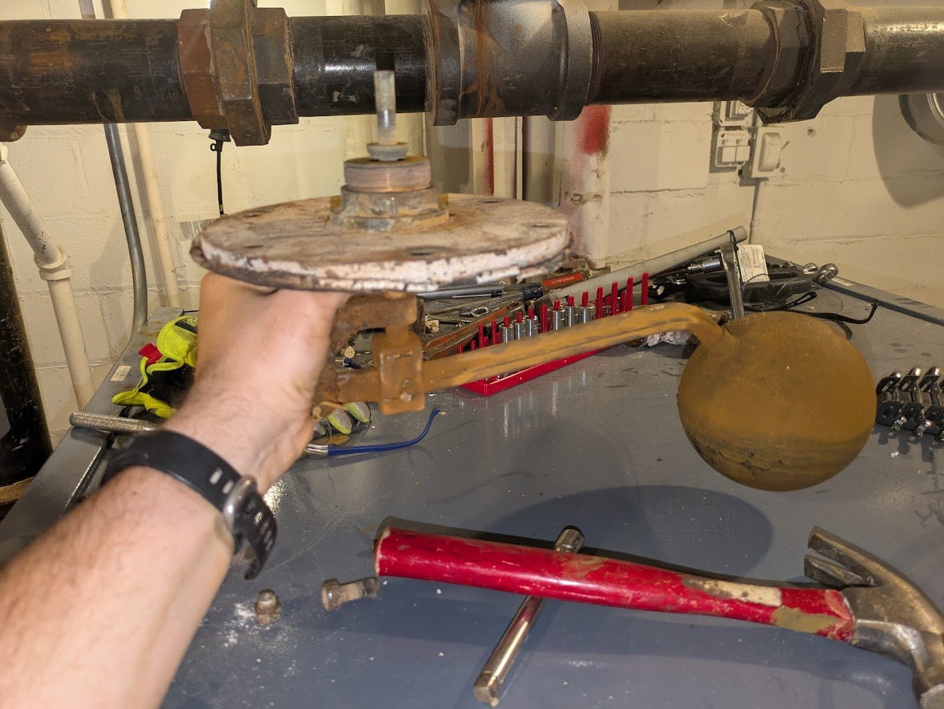
Here's the section that comes out.
It's obscenely heavy. So heavy it's difficult to walk while carrying it around.
It also nearly killed my father in law, who was pulling it out from above head height, and underestimated it. Sorry pops.
And yes. That crimped copper trash up there is what the heating contractor used to attach the cobbled-together venting tee. I mean. It worked. But it's not right.
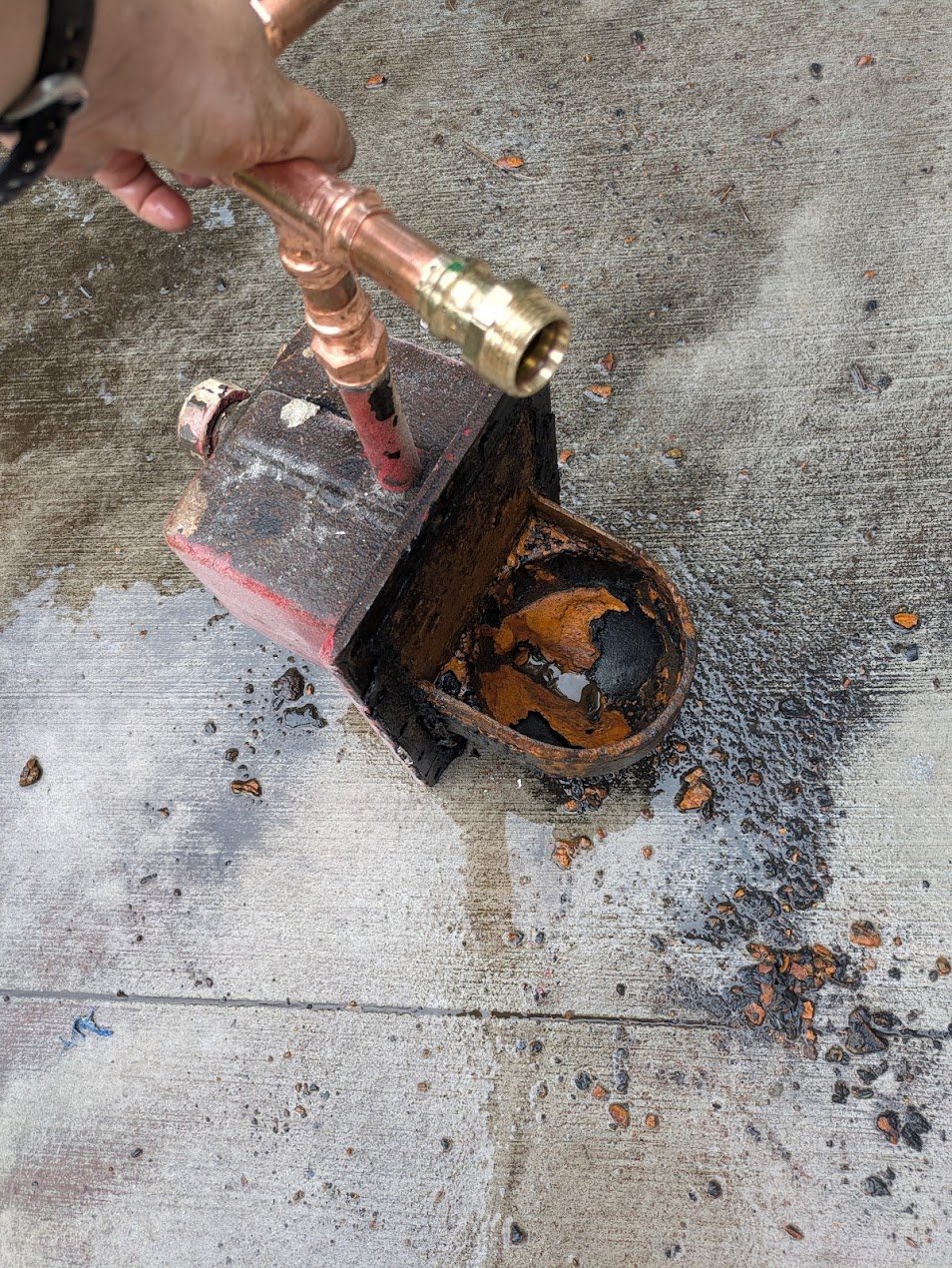
This part of the housing is a beautiful casting that is both one piece and hollow. It has a couple 1" holes inside wall, that allowed the foundry to have a place to blow the sand out of the inside of the casting once it cooled, and then the holes were tapped and plugs were installed to seal the holes. 90 years of rust has made those permanent residents of the casting now. I got access to the inside of the compartment through all the piping connections and cleanout plugs and blasted the **** out of this thing from the inside with a pressure washer. The various holes thoughtfully provide access to all the places inside that you need to reach. Most of the stuff came loose, and I got the passage from the bottom of the "toilet bowl" that leads into the inside of the box cleaned out. There's a cleanout plug in line with that channel on the outside, and I started by clearing the passage mechanically with a long screwdriver. The crud in the bowl was scraped out the same way.
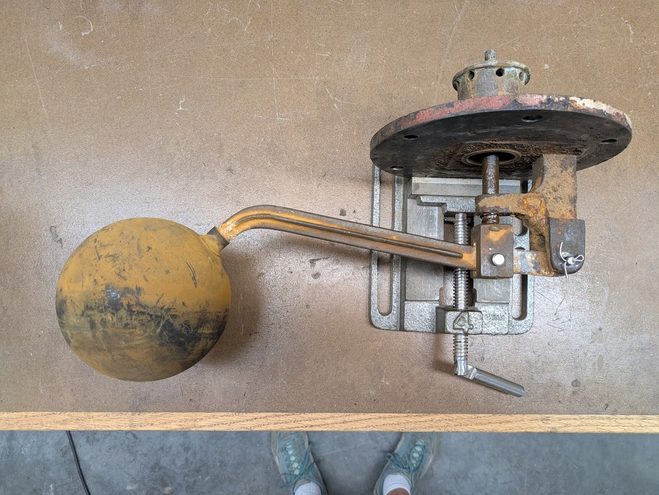
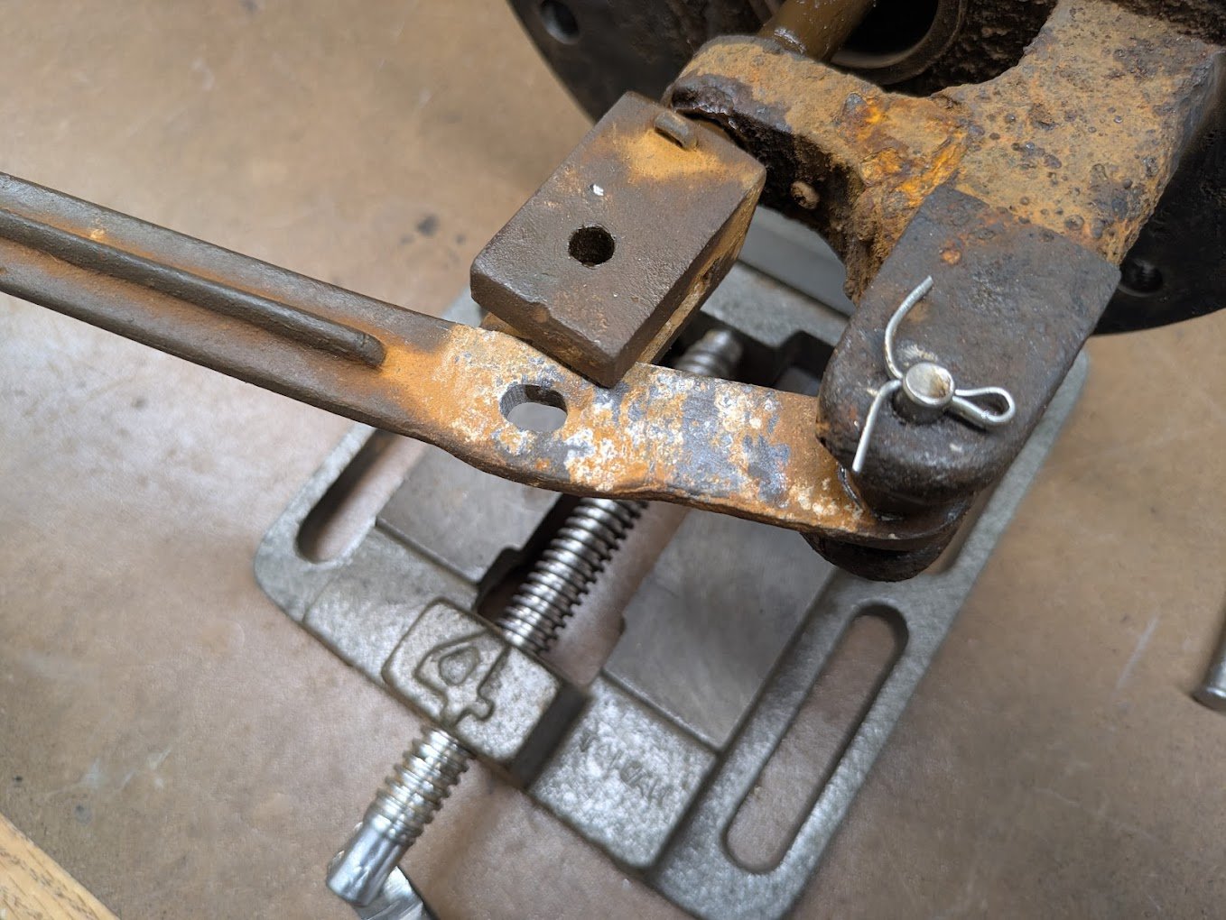
Next up. The float.
The cap and hinges and arm are cast iron. They spent the last 96 years of service in an angry water and steam sauna, and this is exactly how it looked when it came out. Beautiful. The ball is metal and rings like a bell when you tap it. Its fairly thin, but solid as hell, no risk at all of any of it falling apart. Ready for another 96 years of service.
Almost.
The hinge pivots themselves are all gunked up and it's almost frozen solid. Difficult to move by hand, no way float pressure enough could do it.
One hinge pin was brass with cotter pins and I drove it out, the other was iron and and I had to drill it out. I replaced both with stainless steel pins secured by cotter pins.
Real men fix century-old steam heat components in their shop, while wearing blue suede shoes.
My drilling out of the end pin was a little off-center. I had to grind and file the hole in the arm into an oval, to get it back to operating without binding. Note the bent over pin at the top of the movable part of the yoke. The shaft there is threaded, and I think that adjusting how deep it was threaded is how they set the calibrated the height of the float, when it was first assembled.
Reassembled with some lithium grease.
Is lithium grease a good idea inside a steam system? I do not know.
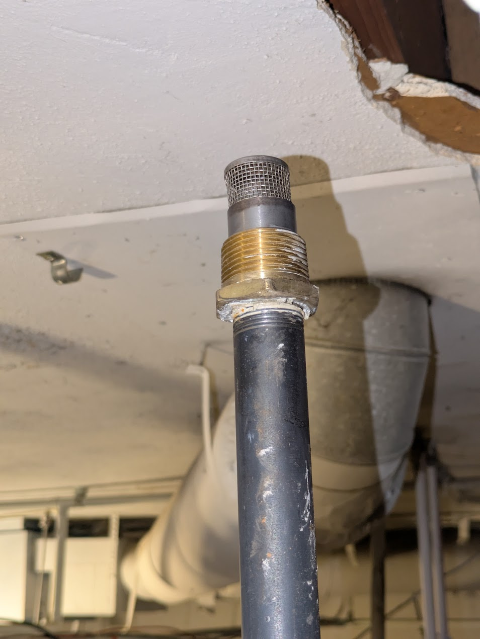
For the curious, here's the valve itself on the outside:
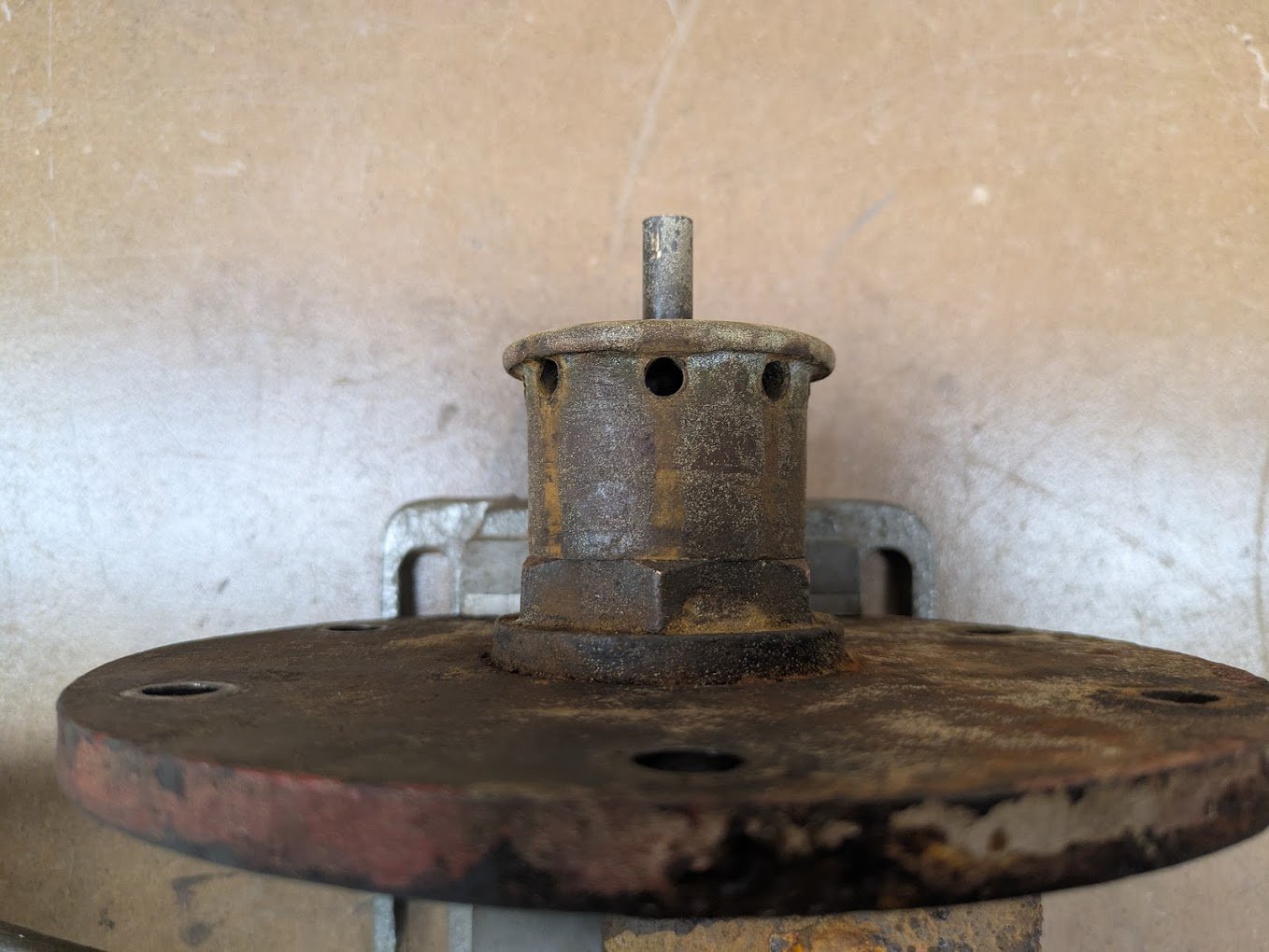
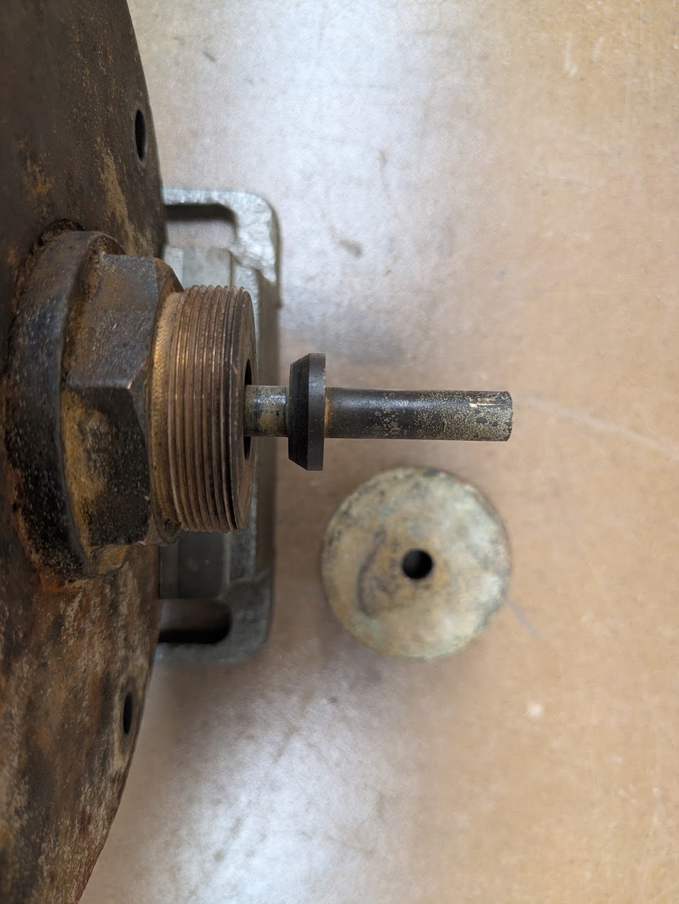
And another picture below with the cap removed. There's a second valve seat on the inside. It seals tight when the float is low, or when the float is high. It seals when the water is low, when it starts to pull vacuum, allowing it to seal and hold the vacuum. It seals when water is high because pressure is high and the water won't return to the boiler. Sealing keeps it from letting the condensate flood your basement while the boiler return trap is trying to do its job. So how did they assemble this? The rod is threaded between the two seats, and so it comes apart in the middle, allowing for assembly. I did that out of curiosity, but I decided not to take it apart any further — the next step would have been to separate the hinge fork from the lower rod (see other photos). I think also that the big threaded brass part maybe comes out? In any case.
There really wasn't a need to disassemble it, and I observed that was secured with a pin, and that it was how the manufacturer had adjusted the float for correct operating height, and that it was caked in 96 years of rust and gunk, so I decided that today was a good day to NOT mess with this part part of the system.
Meddle not in the affairs of wizards.
Now for the housing that's up in the ceiling.
There's an extra cleanout plug — intended as the water fill port — there. That would NOT move, no matter what I tried. After install, the retainor needs to start full of water, with the float… well, floating… or it won't work. We'll need to find another way to fill it.
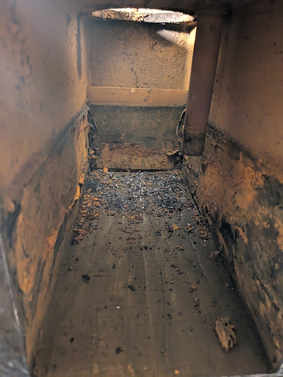
Yup. Paint scraper time. There's a cleanout plug on the bottom, I also removed it and added a size reducing bushing and a 1/4" valve so I can drain/blowdown. It's a little difficult to see but there's a thin sheet-metal dam at the far end, which is intended to prevent gunk in the box from spilling over to the drain fitting at the far end (the pipe opening is behind the dam)
The two halves of the casting were sealed with the same type of squeeze-tube gasket-maker stuff you can buy in the store today. Paint scraper and chisel and and angle grinder with a sanding disk cleaned it all down to bare metal. The parts from deep inside the join, parts that had never been exposed to air since it had been assembled still smelled — 96 years old, but it smelled just like a brand new tire.
Next up, the bolts for the float valve flange at the top. I just drilled them out, retapped them. I had to go up a size in the bolts. There was plenty of meat left in the casting. My drilling wasn't spot on center, so after I sized up the holes in the lid, I also had to adjust them a bit egg-shaped with a file, to get the holes lined up enough to go back on.
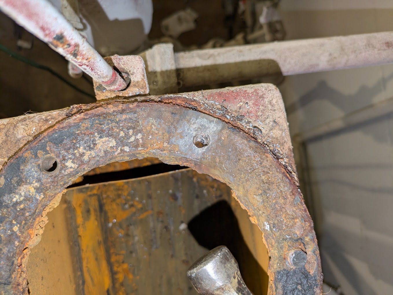
Oh, yeah. Metal shavings. Cleaning round two. Better view of the dam.
 0
0 -
Putting it all together
Reassembly went the same way. Insert the ball into the hole, slide the whole assembly in on the angle, prop some wood under it to hold it angled so the ball is as high as it can go in the case (more than the hinge alone has freedom to move). Put the cast iron compartment and bowl in place, bolt it all together. Hmm. How should I hold it in place so I don't get a flattened spot on the top of my head when it falls out from above me as I mess with it?
I'll use the union in the crossover pipe above it to support it once I get it roughly in place. Also that copper crimp trash needs to die. So let's go back to black pipe. The original piping was beautiful custom-cut-to-length exact pieces. The heating contractor threw those away. So I'll repipe with a bit of a swing arm to take up the slop from the store-bought 1/2 increments. Oh! This would also be a great way place to add a boiler drain valve as a replacement way to be able to fill it with water!
I mean, It's not super elegant. OK fine, it's an ugly hack. But it works. Leave me alone.
So now we assemble the housing in place, and the union is enough to keep it from falling out and giving me a concussion and/or permanent cranial indentation while I'm working on it.
Somewhere along the way in this whole reassembly process, a squeeze tube of gasket maker gets opened, and I apply a thick, but even bead of gasket sealer. First, I apply gasket sealer to both pairs of mating surfaces. Second, it gets applied to my hands and forearms, and then later still, to my clothing, parts of my hair, the bathroom hand towel, the family dog, etc. Once this is done, I hand-tighten the bolts, wait the recommended amount of time time for the gasket sealer to set up per the instructions, and then re-tighten the bolts to final torque.
Side note: Hiding in the back of that picture, you can see the (four) crossover air vents, one at the end of each branch of the main. While the Heat Reatainor housing was disassembled, and the right side compartment was removed, I now had meaningful access to those, for the first time ever, so I opened them all up and replaced the Illinois 1G internals (which amazingly still worked after all these years!) with B&J cage units that have about 5x the venting capacity. Each of them individually, now has about 75% of the venting capacity of a Big Mouth, and better still, I I didn't have to pull them out and screw with unions. Also since the housing didn't change size, I was able to avoid repiping too. Call it a win. I did all those changes a long time earlier, just didn't take any photos of that at the time.
So. Time to fire it up and see how it works.
Problem 1. No vacuum.
Damn it.
OK. But it will pull vacuum, assuming that I lean a stack of 4x4's on the top of the vent shaft, to put some weight on it. So the seat and seal is fine. So what's wrong?
0 -
Bonus round #2: Why does the heat retainor still vent full time?
It's time for round two of this week's episode of "think like The Dead Men". If you didn't participate in round one, I really think you should stop and puzzle on this one for a while. It's a very very satisfying discovery.
Six increasingly powerful hints below, if you get stuck, then the answer.
Barely a Hint 1: This picture, along with the description of how it works from the PDF up near the top.

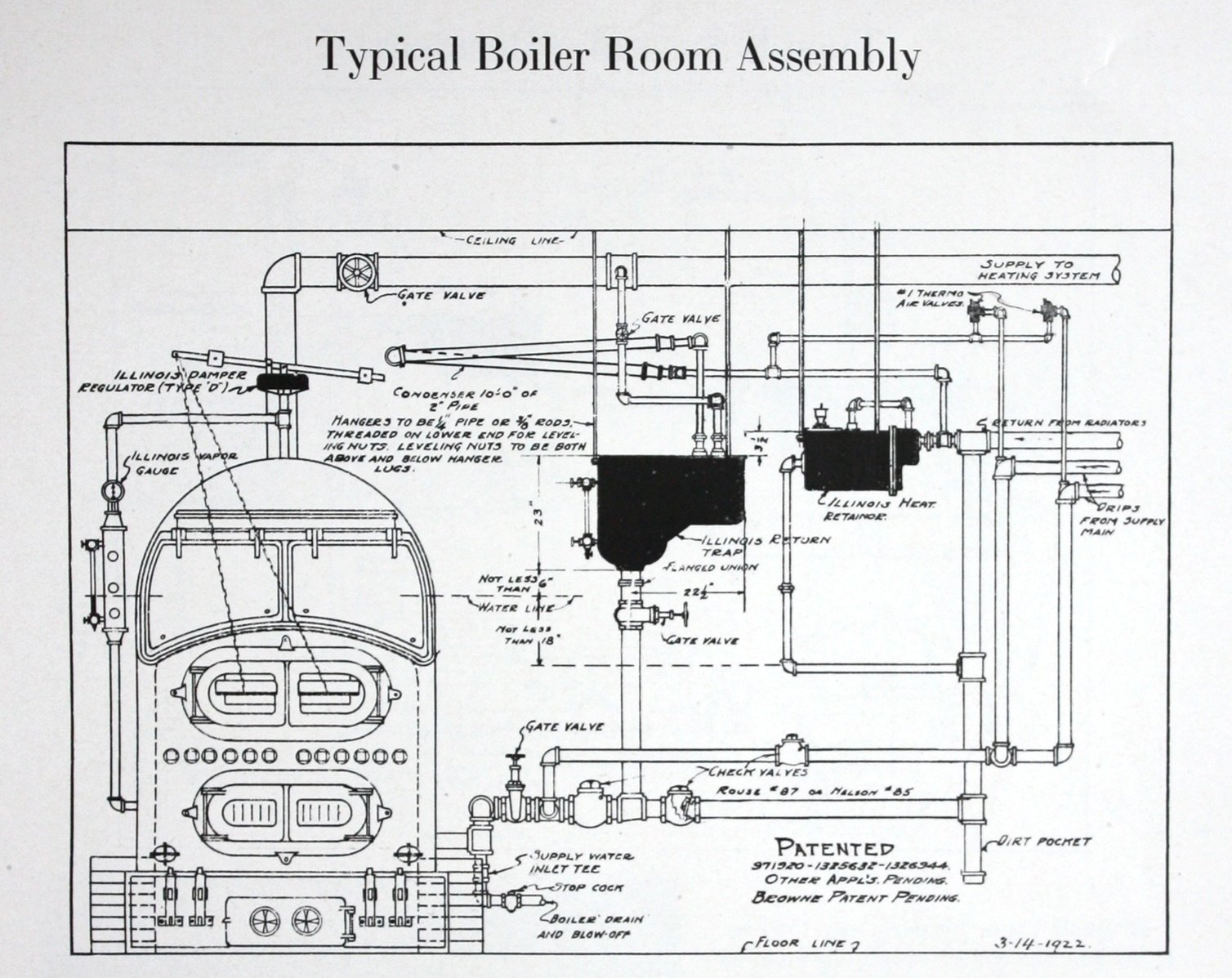
A little Hint 2: Note that the retainor in this schematic diagram below is drawn flipped left for right. So the little box on the left below is what I keep calling, "the right compartment" all through the rest of the discussion so far.
Bigger Hint 3: Both hints 2 and 3 literally contain the exact words that say what the problem is.
Big Hint 4:
Huge Hint 5:
This is not the original boiler for the house, and it is not the same size or shape as the original.
Monstrous wallop-you-over-the-head Hint 6:
The new boiler is a lot shorter than the original.
Solution:
It's the exact same problem as the first time. Just a new path.
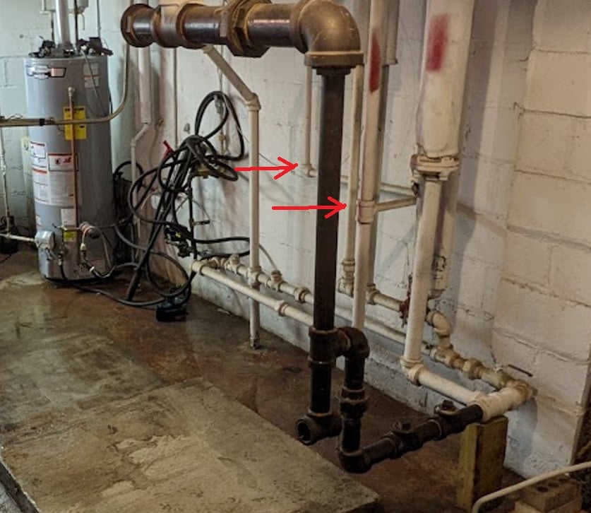
The horizontal pipe with the red arrows is the bottom leg of a water trap that separates the left and right compartments of the Air Retainor. My LGB-8 is not very tall. Certainly not like that cast iron monstrosity from before. The LGB-8's standard operating water line is 4" lower than the bottom of that pipe. Meaning it's now a dry pipe that serves no purpose except to equalize the pressure in the two compartments.
When the two compartments are the same water level, they still think that means zero system pressure.
The vacuum that develops when steam condenses just sucks air in the air vent, down the pipe, across, up the other pipe, and relieves the vacuum. So the water level never moves, and the vent never seals, so there's never vacuum.
In fact, this says that this system has not once been able to draw a vacuum and operate the way it was designed to do, ever since they converted it from coal to HHO and later to gas, probably sometime in the '40s or '50s.
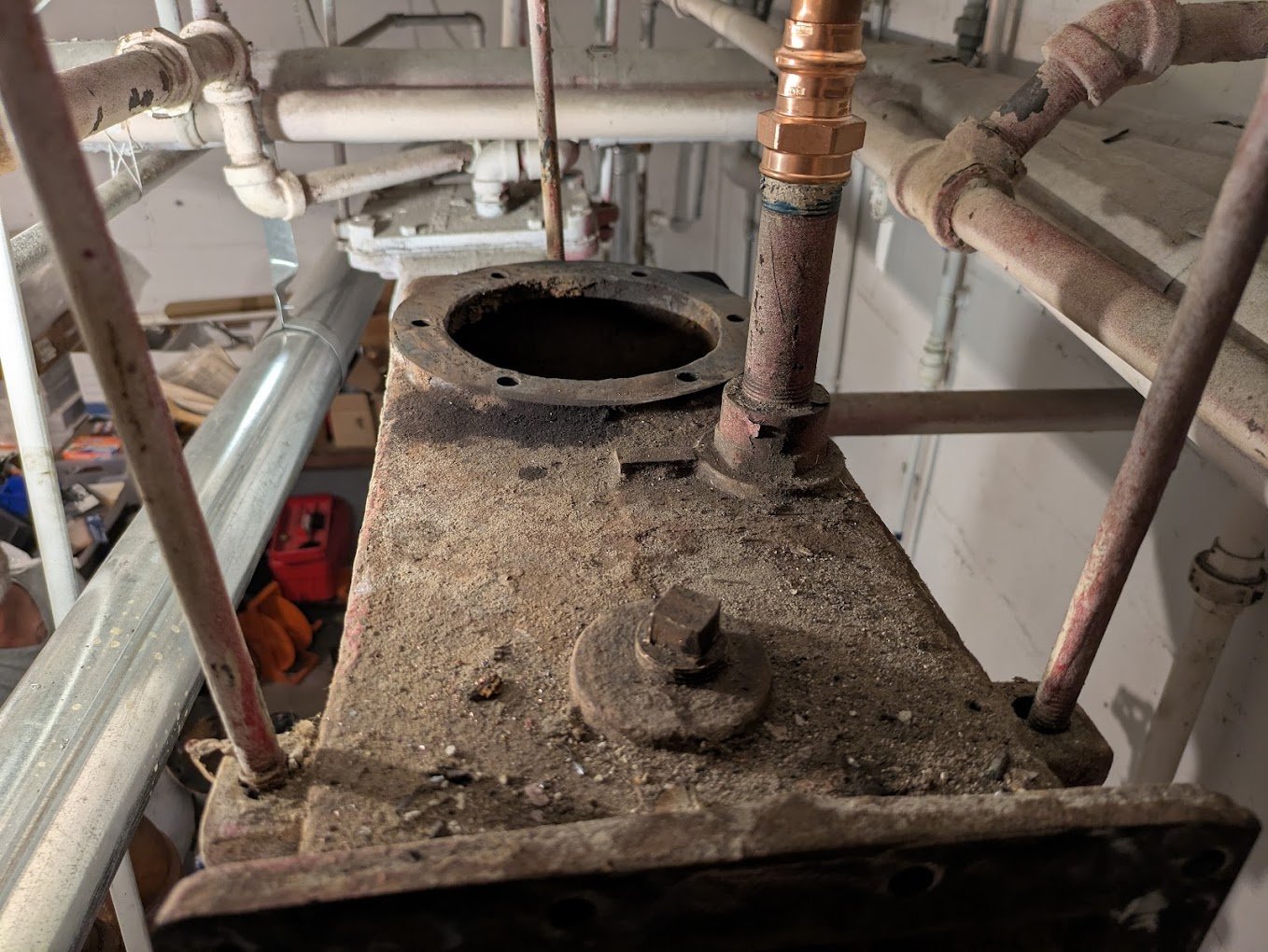
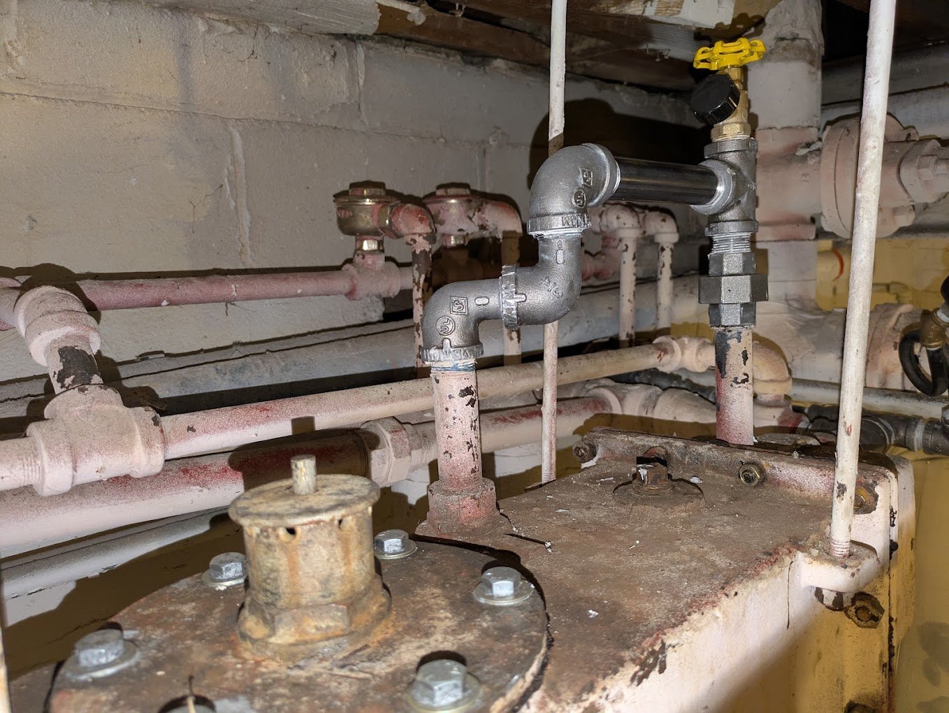
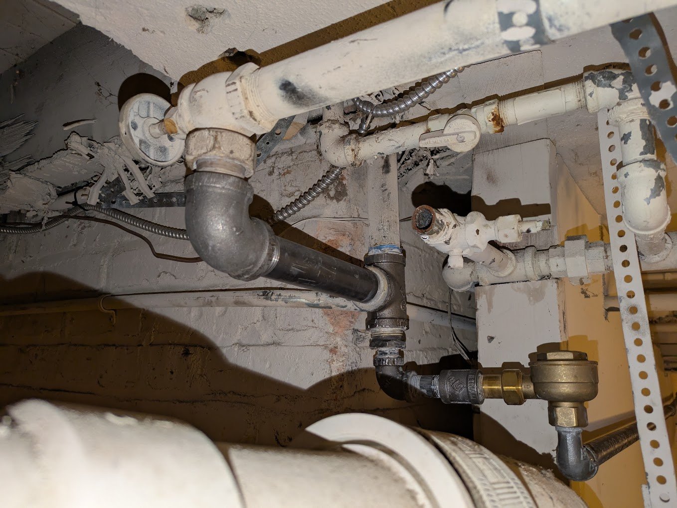
So. To fix it, it's time to repipe. The old reducing tee on the rightmost vertical pipe in the picture below is where this horizontal leg used to to return to, and from my wall markings, you can see it to be above water line.
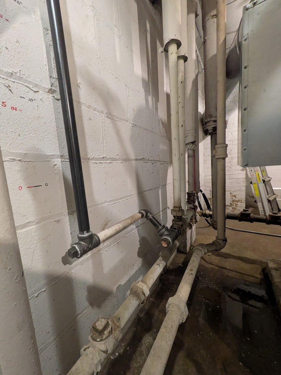
I altered piping, and ended up changing slightly. Now the condensate from the retainor returns a little further downstream. This is technically now on the wrong side of the two swing valves associated with the return trap per the install instructions, but it does work. It's returning condensate the same place my end of main drips are, so that's fine. I'm not sure if it would work or if it would overflow, if I actually ran enough pressure to cause the return trap to be needed. But… why would I ever want to allow this thing to hit 30" of operating pressure? No way.
And with gas, preventing that is easy. I've installed an operating limit vaporstat that is impossible to set any higher than 16 oz.
0 -
Further work that was needed along the way:
Two parts of the system were repiped in the 60s, and both introduced water hammer.
In one case I had a low spot in horizontal piping on both first and second floor that would both collect water. I was able to repipe and lower the riser by 2" which provided helpful backslope upstairs, and helpful forward slope in the basement, making a single low spot where the water would reliably collect. I then added a tee and thermostatic trap, making a mid-main drip, and returned the condensate to the same place as the end-of-main returns go. This run of pipe still needs to see 4 oz of pressure, only for a few seconds each cycle, to blow out some residual condensate upstairs. Honestly not sure if the low spot is in the main or the return, but it doesn't really matter. As long as I see a little pressure each cycle, it clears, but that happens gently enough that it never hammers. I have a system that works. Better is the enemy of Good.
Here's how the mid-main drip looks. the main is horizontal at top, transitioning up to vertical to get to second floor. The shutoff valve used to be turned 90 degrees, making a side exit that went horizontal into a 90 at the bottom of the riser. The valve and horizontal pipe were the low spot, so it would flood and air-lock. Probably it used to just barely be pitched ok, maybe only by a quarter inch even, but then part of the house settled, and things changed.
In the other case, there was a part of the house that was an addition, that later got a gas forced air furnace and air conditioner unit added — I presume because the pipes weren't sloped right there either, and it hammered like hell. They apparently removed the radiators and plugged the connection tees, but they obviously didn't rip up the house to remove the mains and returns out of the floors, they just turned the valves to shut down that part of the house. — However, when the heating contractors replaced the boiler, some very smart man on their crew thought it would be a good idea to go all over the house, and he opened every steam valve he could find without bothering to ask where any of them went. This put steam back into the sagging pipes in the guest room addition, and so it hammered like hell again.
But how would I know that was new? It didn't hammer when I moved in. (Because the steam didn't work.) Eventually I figured out that I had one more valve than I had rooms, and realized that shutting it off isolated the bad section that had been replaced by forced air heat, and now it's quiet again.
Interestingly, the only gate valve to isolate that part of the house was at the very end of the return, where it joined the main returns in the basement. There's no cutoff on the steam main. Either way, with the valve closed, no air moves, so the pipes don't hammer.
0 -
Final Results:
16 oz operating limit.
0 oz low-rate cutoff with 4 oz differential. It trips to low-rate as soon as there's any pressure at all, but pressure overshoots to 6 oz because of response time and time for the two stage valve to close. Over the next minute it drops back down to 0 oz as steam keeps hitting the radiators and needs to be replaced.
With system shutoff, it goes into vacuum as the steam starts condensing, and the low-rate cutoff resets. While cooling over the span of an hour, it pulls 12 inHg of vacuum, on a schedule tied to falling boiler water temperature — It stays either just at the edge of still making vapor, or perhaps still is, if only negligible amounts, the whole time. Once it reaches 12 inHg of vacuum, it will hold that pressure for 8 hours.
When the system starts its next cycle, it's starting at high rate burner, under to a boiler at at 11 or 12 inHg of vacuum and 180 deg F. With that much vacuum, the boiler starts producing and delivering vapor steam by the time it's up to 185 deg F. Not a lot of steam, but enough to begin preheating pipes and radiators. It's so slow and gentle, all the ticks and pops and bumps from heat expansion are now whisper quiet, compared to what they were before. By the time I get to 212 and 0 oz of pressure, my radiators are already warm, and the dual rate kicks in. It overshoots to 6 oz, then falls back to 0, and I run dual rate indefinitely, with hot radiators, operating at literally 0 oz of system pressure.
Here's to the future.

 1
1 -
Also thanks to all the contributors in the thread linked below. The info that was already available in that thread was a huge part of figuring all this out.

 3
3 -
I love threads like this - it's like watching some restore a classic car or computer or something. Nice work!
1

Categories
- All Categories
- 87.5K THE MAIN WALL
- 3.3K A-C, Heat Pumps & Refrigeration
- 59 Biomass
- 429 Carbon Monoxide Awareness
- 124 Chimneys & Flues
- 2.2K Domestic Hot Water
- 5.9K Gas Heating
- 119 Geothermal
- 168 Indoor-Air Quality
- 3.8K Oil Heating
- 78 Pipe Deterioration
- 1K Plumbing
- 6.6K Radiant Heating
- 394 Solar
- 15.9K Strictly Steam
- 3.5K Thermostats and Controls
- 56 Water Quality
- 50 Industry Classes
- 50 Job Opportunities
- 18 Recall Announcements