Radiators heating even though their zone pump is off.

Hello, I am hoping to get some advice from the hydronic heating experts here. I have a Navien Combi boiler system that was installed about 3 years ago. Our house is radiator heat with radiant floor in the kitchen addition area. Our system has three zones each with it's own pump and there is a fourth pump to boost the flow to the kitchen radiant. Pump control is handled by the Navien.
The functional problem that we are having is that the 1st floor (includes kitchen radiant) and 2nd Floor zones are overshooting their thermostats by between 3-5 degrees F. This has probably been going on since the initial install but I picked up on it last winter and thought that the issue was too much radiator and too high of a set point temp. Lowering the set temp seemed to help.
I have now come to the realization that the real problem is that when our Porch Zone is operating, at least some parts of the 2nd floor and 1st floor zones are also circulating and heating.
The porch zone is the smallest with 2 med/large radiators and a 6ft run of baseboard in the garage below the porch. The porch was converted to 4 seasons in the 80s and it is poorly insulated and as such calls for heat the most often. As a result of the other zones circulating (partially at least) whenever the porch zone is active, the first floor and second floor overshoots and become too warm.
I double checked that none of the 1st and 2nd floor radiator pipes were accidently attached to the porch zone. Nothing appears to be misrouted.
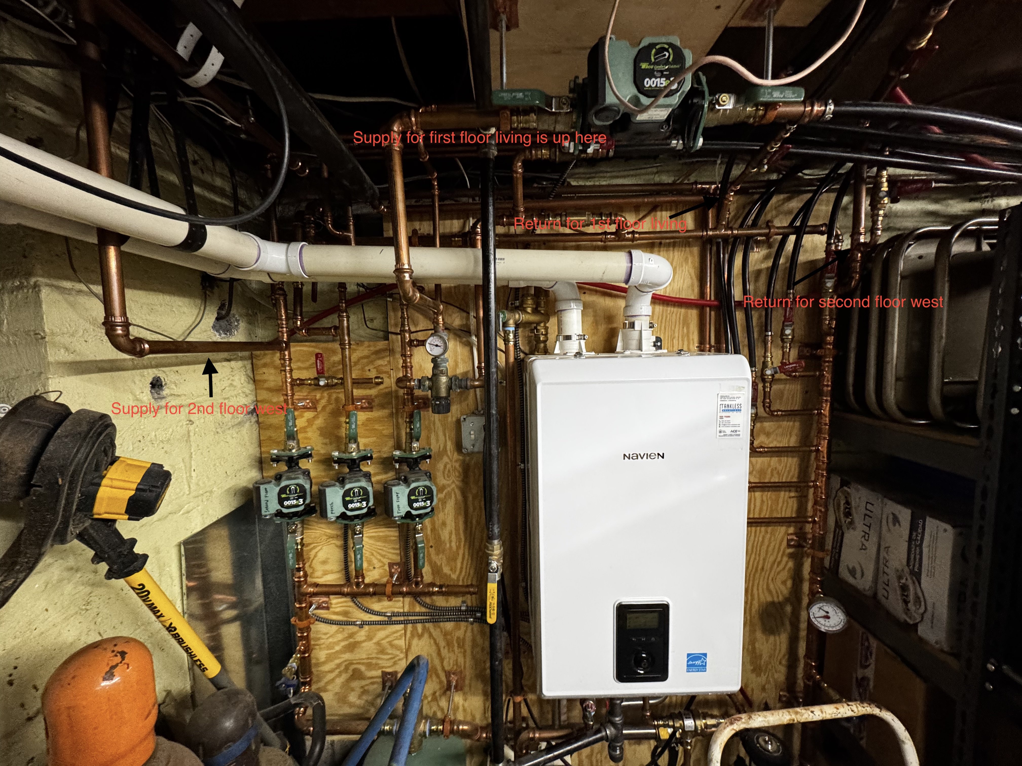
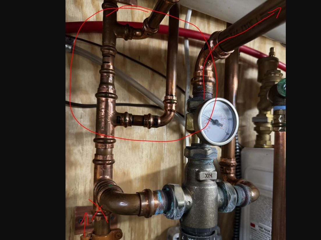
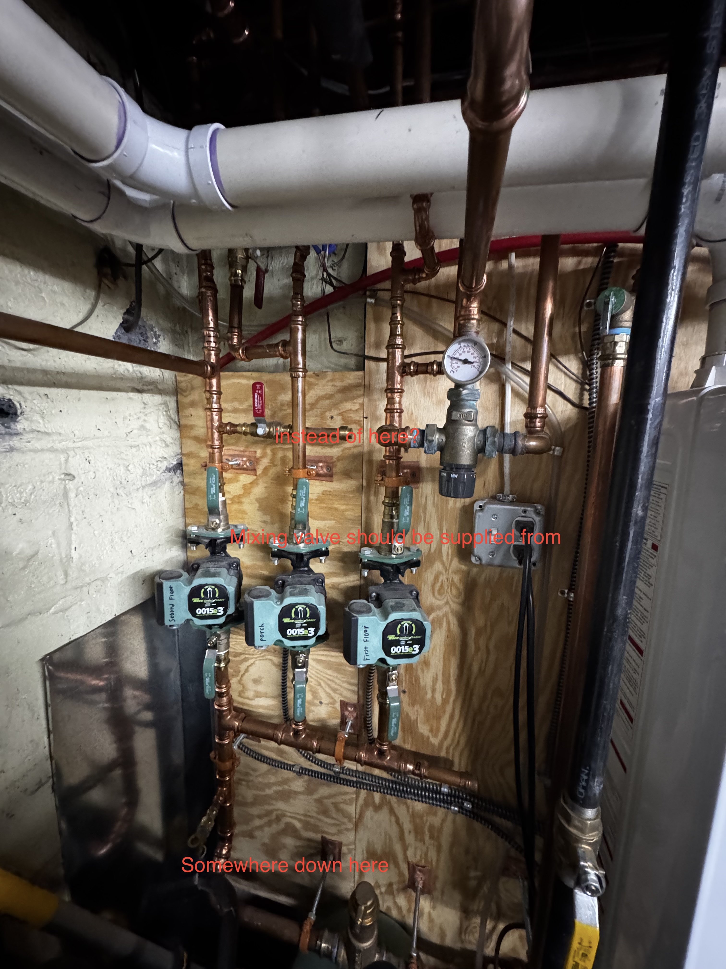
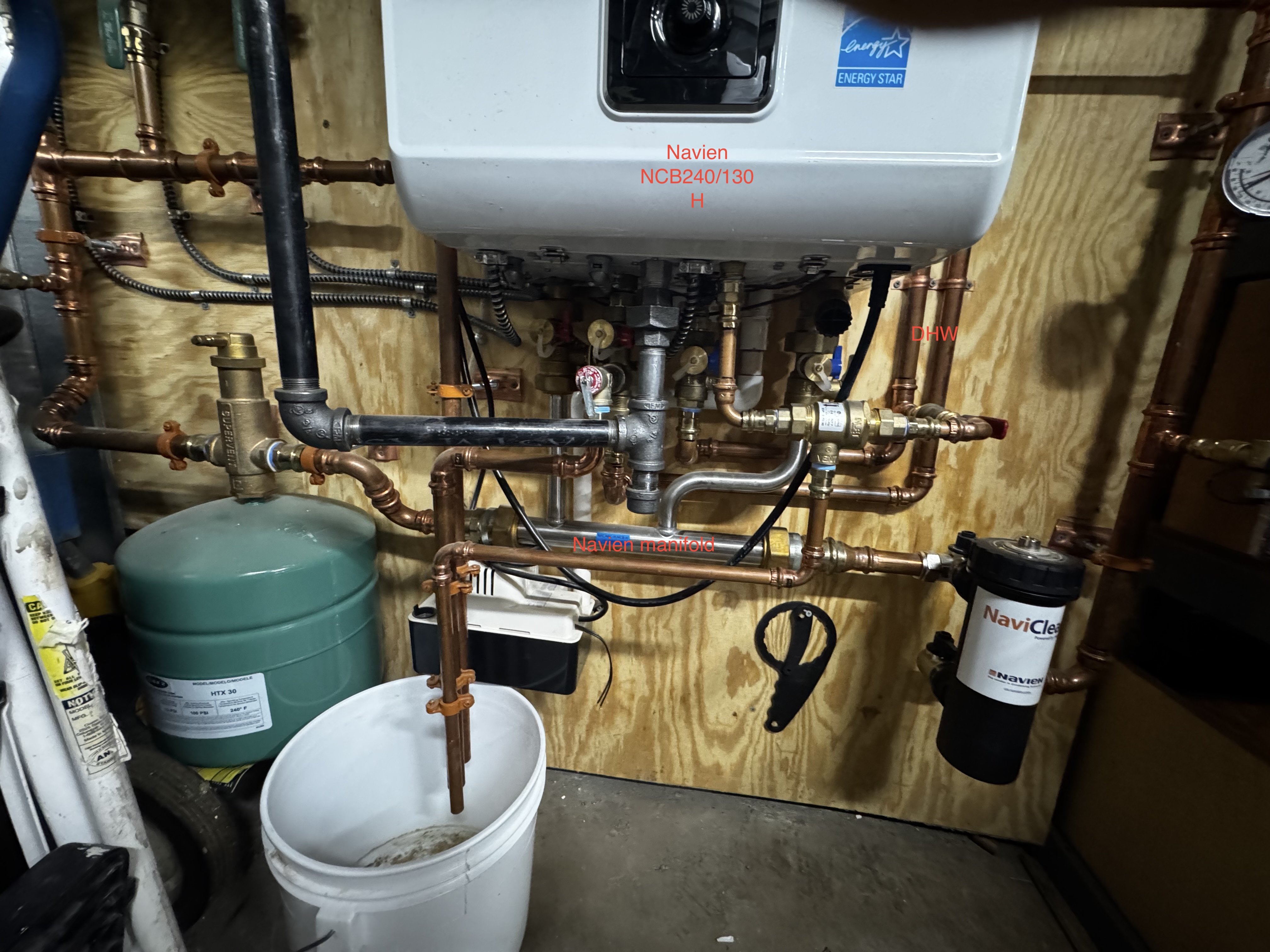
I have attached some pictures of my boiler setup and in the first picture I (poorly) marked the the supply (arrow on the left) and the return (arrow on the right) that seem to be the biggest cross zone offenders. These pipes go to the west part of the 2nd floor zone.The piping for these is 3/4 and when the porch zone is running they get up to full temp to the point that they are uncomfortable to touch. As you can see the supply is part of the 2nd floor zone yet when the porch pump is running (middle pump) hot water loops through 2nd floor west.
Can anyone tell me what is causing this? Do I need zone valves in addition to the pumps? Is it a piping mistake?
I am happy to provide more specific pics if needed. Thanks!
PS: I will bring this up with my installer but wanted to get my head wrapped around it first.
Thanks!
Comments
-
The right arrow is hard to see. It is in the upper right hand part of the picture pointing to the 3/4 return pipe that ties into the return "stack."
0 -
it is hard to piece Al. The pics together. Is there a primary loop that the boiler ties into, the boiler having its own circ?
Are there checks in all the circs?
Maybe a drawing would better show the big picture
Bob "hot rod" Rohr
trainer for Caleffi NA
Living the hydronic dream1 -
I believe the Navien boiler has it's own internal circulation pump but I am not certain. How can I tell if the the external circulation pumps have their own check valves? Does the check valve shut off the flow off water through the pump or does it just keep it from going the wrong way? First pic shows the whole system more or less. The second pic is the supply side and the third is the return. Here's a pic of the return pipe for 2nd floor west that get really warm when the porch zone is running.
0 -
a check prevents what is called ghost flow. Ghost flow is when a small amount of flow is moving, induced by temperature difference. Basically a thermosiphon, hot water rising, colder water coming down. It can happen in a single pipe hot rises up the center, colder water coming falls along the sides. So a check in or after the circs prevents that. Also reverse flow is possible if the circulators are served from a single manifold.
Ocassionally a check is needed on supply and return.
The piping an hydraulic separation, or lack of will determine the need for checks.
Some circs have a sticker indicating a check has been installed in the body.
 Bob "hot rod" Rohr
trainer for Caleffi NA
Living the hydronic dream0 -
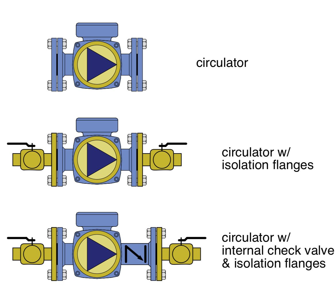
on the CAD schematics I’ve attached, the black slash mark in the circulator indicates the ICF internal check valve
 Bob "hot rod" Rohr
trainer for Caleffi NA
Living the hydronic dream0 -
that boiler needs to be piped primary secondary. I think Navian offers a header kit option. It may be that silver pipe just below the boiler. If it has a pump in the boiler and is piped without that header or another device you could be getting that unwanted flow
 Bob "hot rod" Rohr
trainer for Caleffi NA
Living the hydronic dream1 -
Thanks for all the info. The boiler does have a Navien manifold mounted to it. I have included a picture of the underparts of the boiler and also the circulator pumps. The pumps do have isolation valves but I don't think they have check valves built into them. I have done a bit more checking and I am pretty sure I am getting significant reverse flow in the system. When I let the piping cool off and then restart the porch zone, the RETURN pipe for second floor west (right hand arrow in my first picture in my first post) gets very hot almost immediately while the supply pipe (left hand arrow) gets warmer gradually.
So if the other zones are reverse flowing when the porch is running then it sounds like the porch is then not getting proper temp water due to the mixing. Seems like this then becomes a self feeding problem because the porch zone runs almost constantly trying to heat up with less than full temp water while at the same time the other two zones get heat even though they aren't calling for it.
What's the solution? Would installing a check valve on each circulator solve it? Is that simply a part that would replace one of the isolation valves above or below each circulator. Things are tight but it looks like there is just a bit of room for a longer isolation valve above each pump.
Thoughts? and thanks!!!!!!
Eric
0 -
0
-
I just checked the info for the Taco 0015e3 circulator pumps that I have and they are supposed to have integrated check valves. Is it somehow bypassing the check valves or are they bad or maybe never installed? We have had the system for at least 3 winters and I don't remember this being an issue the first winter so maybe the valves have gone bad or are now stuck. Seems strange after just 3-4 years.
0 -
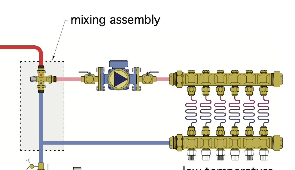
Where is that 4th pump "to boost flow" located that you mentioned? From the pics I was able to see the mix circuit pump (the one in line with the other 2 pumps) is in the wrong location pumping towards the mixing valve where it should be on the mix outlet of the mixing valve. I'm thinking that may have something to do with your problem.
0 -
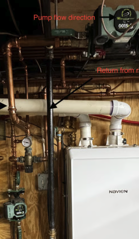
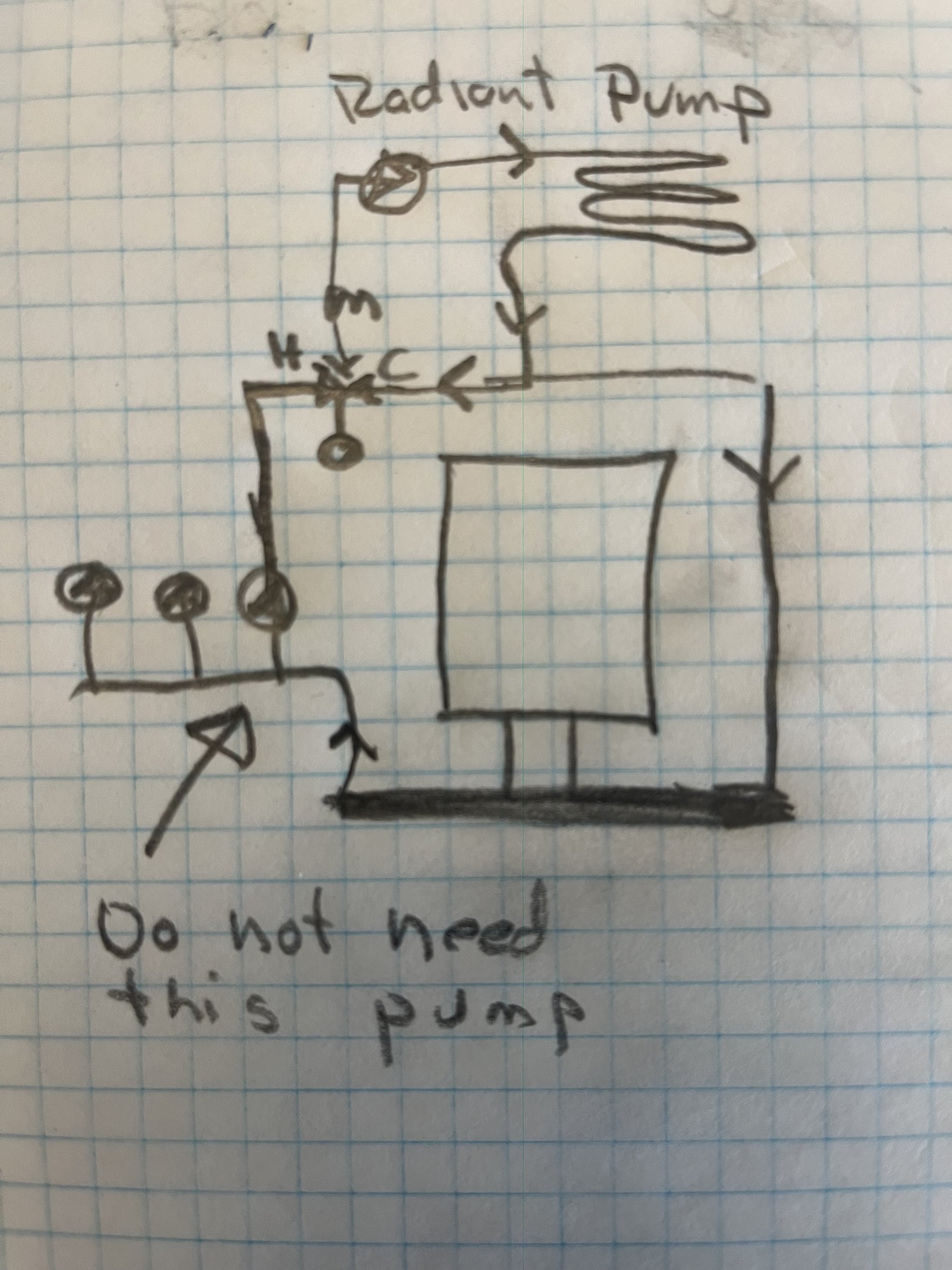
Here are two pictures that I have marked up. The first shows the pump locations. There are three pumps for each zone located in sequence in the lower left and then there is the radiant floor circulator in the upper middle of the picture. As far as I can tell it is pumping in the correct direction. Also this problem exists when the 1st floor zone (which the radiant circulator is tied to) is off so I don't see how that pump could be part of the problem.
The second picture shows the two loops that are reverse flowing; 2nd floor west and 1st floor living. Please look carefully for the black arrows (my stupid program won't let me change the color:( ) These are on two different zones. If other loops are reverse flowing it is minimal. I have also discovered that even if I completely shut off the isolator valves for the 1st and 2nd floor zone circulators that the problem still continues so it is not an issue with the integral check valves. The reverse flowing loops are not using the circulator supply piping to create their loops.
It seems like if a check valve is installed in the 2nd floor west return and in the 1st floor living return that it will solve the problem. What do you guys think?

 0
0 -
Something doesn't look correct here. The mix valve just needs the one circulator on the H port, the upper most circ.
Hard to tell but it looks like the lower pump is also tied to the H port of the mix valve? If so, that will push some flow into that mixed low temperature circuit even when the upper pump is off.
 Bob "hot rod" Rohr
trainer for Caleffi NA
Living the hydronic dream1 -
More complications. If I use the existing in line shutoffs to stop flow for the 1st floor living and 2nd floor west returns then the problem moves down the line to other loops. It seems crazy to have to put check valves on the all the returns but maybe that is what is needed?
0 -
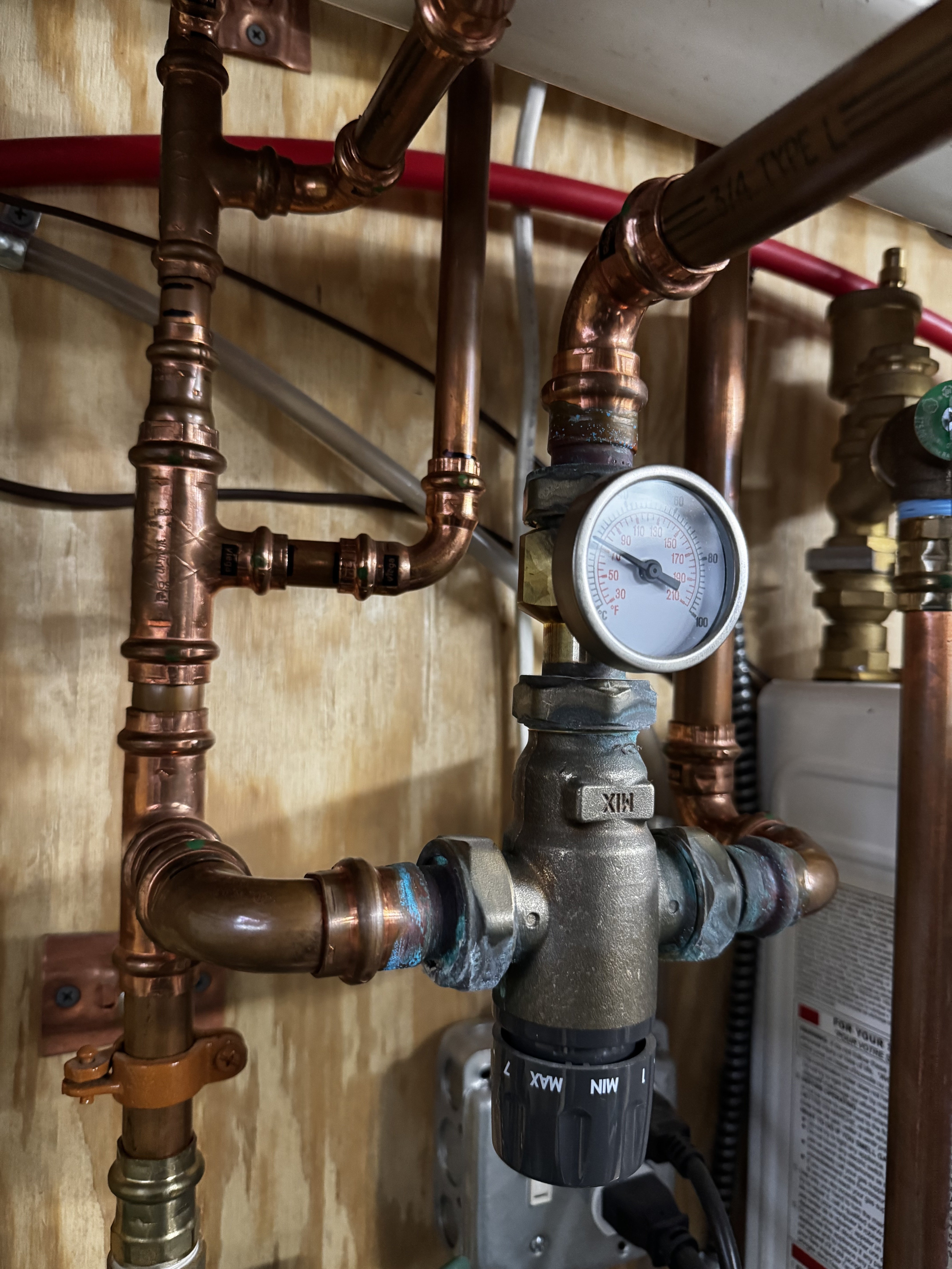
No the mixing valve "h" port only has the pipe running straight to the radiant circulator. Here's a close up.
 0
0 -
what is the purpose of the rest of the piping on that mix loop? there are two tees and the supply continues out as well, is there more than one zone on that line? if so that lower pump is probably setup to energize when the mix circuit calls, that lower pump doesn't need to run at all when the mix loop is calling
 1
1 -
Only the first floor zone is on that line. On the mixing valve, the left side is the supply (its just above the circulator pump for the first floor zone) and right side of the valve is the return. As you follow the supply pipes up they feed various 1st floor loops.
Presumably the mixing valve doesn't allow flow from left to right, or right to left (in the picture) but only allows exit flow out of the top "H" port.
Problem is in two zones so even if the mixing valve is messed up that doesn't really explain issues with the 2nd floor zone.
All the returns are interspersed so that seems to make it impossible to just put one check valve for each zone. What is happening I think is that some parts of the return stack become supplies.
0 -
doesn't make sense to me. I am talking about the two tees in your most recent photo
circled here. you have a pump pumping direct at the mixing valve there which is incorrect, and you have a pump on the mix out which is correct. I am wondering what the purpose is for the extra supply, and the 2 tees on that line, it looks mispiped to my eye
 0
0 -
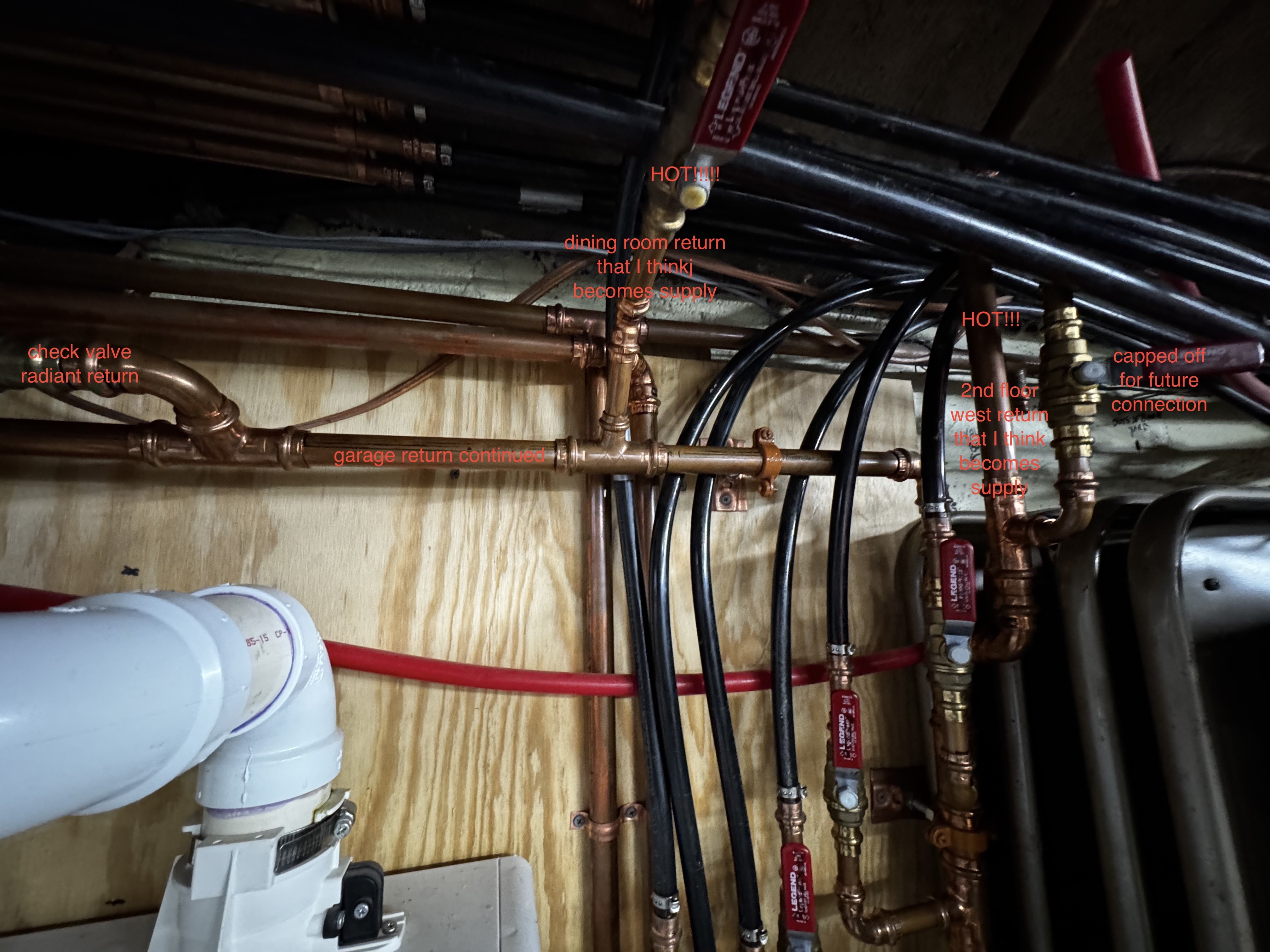
Here as some more pictures of the area that might be problematic. I did shut off the garage (part of ther porch zone) loop but the two reversing loops still heated but perhaps not quite as strongly. Edit it should say living room instead of dining room return in the third picture.

 0
0 -
Can you explain why the circulator pump for the 1st floor zone shouldn't be connected to the supply side of the mixing valve? Doesn't the mixing valve need to mix the hot supply water with the return water from the radiant? The "h" port then supplies the mixed water to the radiant circulator. Are you saying that they should have taken the supply water from before the main 1st floor circulator pump?
What you have circled are supplies for the RADIATOR loops of the the first floor zone. The first floor is a combination of higher temp radiator (circulated by the main 1st floor pump) and lower temp (reduced by the mixing valve) in floor radiant circulated by the upper pump. How is that misspiped? I don't get what you are saying about these particular pipes.
0 -
the radiant loop only needs the pump near the ceiling, the one pulling from the mix port
If there us a second pump, down lower connected to the H side ut will push head even when the radiant pump is off
 Bob "hot rod" Rohr
trainer for Caleffi NA
Living the hydronic dream0 -
The mix
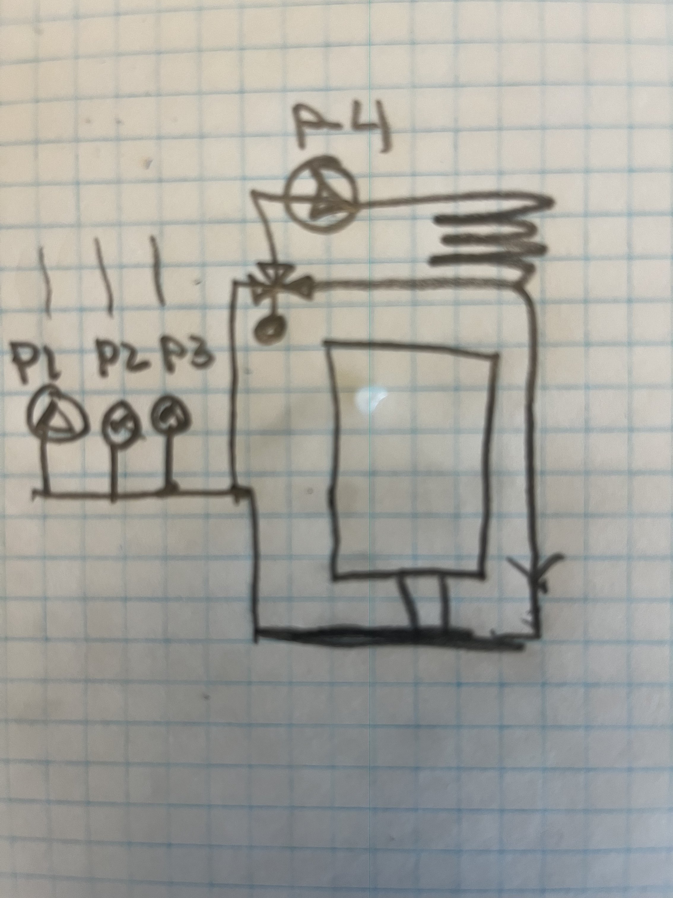
valve connects to the main loop, only 1 pump, P4 after the mix valve
Bob "hot rod" Rohr
trainer for Caleffi NA
Living the hydronic dream1 -
Ok. So the mixing valve should get its hot water from between the boiler and the first circulatory pump? I can discuss this with my installer. The thing is that both the radiant floor circulator AND the main first floor circulator turn on at the same time the first floor thermostat calls for heat. So there will never be a time when the main circulator is pushing water into the radiant floor loop when and the radiant circulator is not operating. So the question is, is this even really an issue? Will it make the mixing valve work incorrectly? Will it burn out the motors? I was imagining the radiant pump more as a booster pump. The Navien can only control 3 zones internally so the radiant zone was combined with the rest of the first floor. If in the future I added an external zone controller then it would be nice to have the mixing valve supplied properly so I could then put the radiant on its own zone / thermostat. As it is now, it works pretty well as one zone except of course the for the current overshooting problem when the porch zone is running.
As to my issue, the first floor zone (which includes the two pumps we are talking about) is not even active when my over shooting problems are occurring. That happens when the porch zone is running solo. While the mixing valve piping might be incorrect, how does that impact the reverse looping issue?
0 -
 0
0 -
Well, it's not correct piping if that is what you are asking. I'm not sure the effect of having both pumps on the mix valve like that. It probably depends on what position the valve cartridge happens to be in.
There is room to the right of the lower right pump to pop an ell in and pipe it correctly.
Bob "hot rod" Rohr
trainer for Caleffi NA
Living the hydronic dream2 -
Ok. Thank you! I was thinking that it had to be before all the pumps started but if connecting to that stub at the end (to the right of the first floor circulator) isn't a piping no no, then that clearly would be where to pipe it from.
Now what can I do about the radiators (living room and 2nd floor west at least) from other zones heating when only the porch zone is running?
0 -
Check valves are a must in a zone pump system. You have isolation valves on both sides of the pumps so it is easy enough to pull on out and see if there is a check in it. If not I think you can buy the checks and insert them. The installer that put the pump on may have them in his collection?
I'm not sure these fit them 0015E? @Joe Mattiello may know
 Bob "hot rod" Rohr
trainer for Caleffi NA
Living the hydronic dream1 -
Thanks. I actually did already pull out the second floor zone circulator and the check valve was in place and seemed to be functioning / not stuck open. It did look pretty much exactly like those ones that you linked. I also went ahead and shut off the the isolators for the 1st and 2nd floor zone pumps and still the the first floor living and second floor west loops were heating. Those loops are looping without using their zone's supply water so some of the returns most be turning into supplies.
0 -
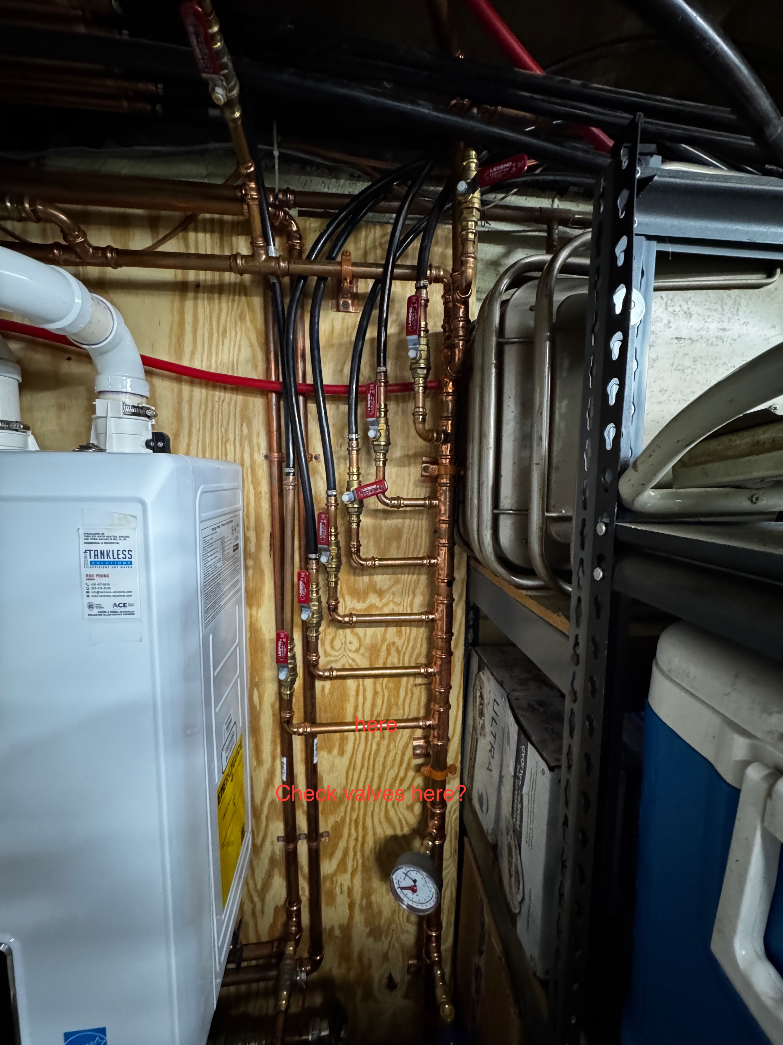
Here's a picture of the return stack. Let's say I was to install in line check valves. Would you place them on the copper horizontal runs (see picture) when possible? Swing style or spring style preferred? I suppose I can buy a box of 10 half inchers and a few 3/4s and request my installer put then in for free.
Unless there is some other better way to fix it that doesn't involve starting from scratch on the return stack?
Thanks again to everyone who has helped!
 0
0 -
If it were me, I would correct the 3 way valve piping first.
You could still wire the main floor pump and radiant pump to run off one thermostat for now until you get a relay box to separate the zones. No need to start chopping in check valves until you determine the cause of the cross over.
Then for the other issue, when the porch zone only is running, start turning off various ball valves ( a ball valve is a manual check valve for troubleshooting), to determine which is crossing over or backflowing. You just need to use a process of elimination to narrow down the unwanted flow. This could take hours, days!
It's not easily done over the internet :)
Do you have accurate strap on thermometers to make temperature determinations. You should be able to do the troubleshooting in the mechanical room. Get a pad, pencil, and start recording temperatures and effects any changes make.
Bob "hot rod" Rohr
trainer for Caleffi NA
Living the hydronic dream 1
1 -
Ok. I will do a bit more exploring. I do construction for a living but don't have press fit tool equipment to make the changes, so either I get myself the equipment (which I have been tempted to do for years) or I rely on my installer. In that case I think he and I would both prefer to solve the problem in as few visits as possible. Also it means draining some / much of the system for each change.
Just to reiterate what I have posted earlier. . .Just by using my hands I can tell that when the Porch Zone is running that the 2nd floor west return and 1st floor dining returns are super hot and MUCH hotter than their supplies so I am pretty certain that those returns are becoming supplies. When I shut off those returns, then certainly the problem in those loops go away but then I noticed that other loops started getting hot at their return valves and so the reverse flowing loops just seem to move down the stack. That is why I thinking I was going to just put check valves on all the returns.
I can play around with combinations of different parts shut off to see if I can put together a configuration with as few check valves as possible. I also have a point and shoot thermometer than should give me an idea of what changes make improvements even if they aren't completely solving the issue.
I do appreciate all the info so far. I also realize that I am just going to have to play around myself to try and solve it. Initially I was just hoping for a smoking gun that I didn't see. Even though the mixing valve piping is screwy, I don't feel like it is the smoking gun as far as the loops that are heating when their zone is off.
0 -
Correct, the check valves would stop that reverse flow. Ideally it would be good to know why you are getting reverse flow. Water takes the path of least resistance, so some how it has a path to make that 'round trip.
We would like to treat the problem, not the symptom. But in some cases the check is a needed component.
Sometimes making a hand sketch of the piping you can see the path the flow is taking and solve the unwanted flow condition.
There is a lot of copper tube going on in those pics, I suppose some is potable water? So it is hard for me to tell where pipes connect or just cross behind one another.
Eyes, and hands at the jobsite are the best way to fix this without firing the parts cannon at it.
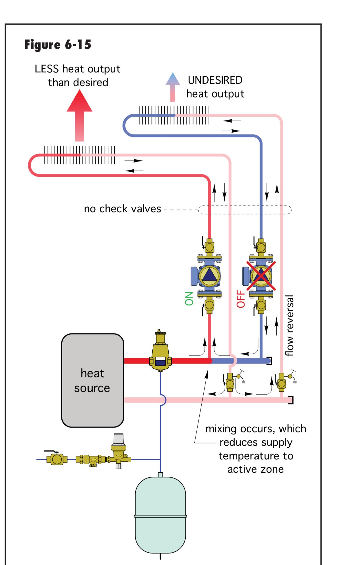
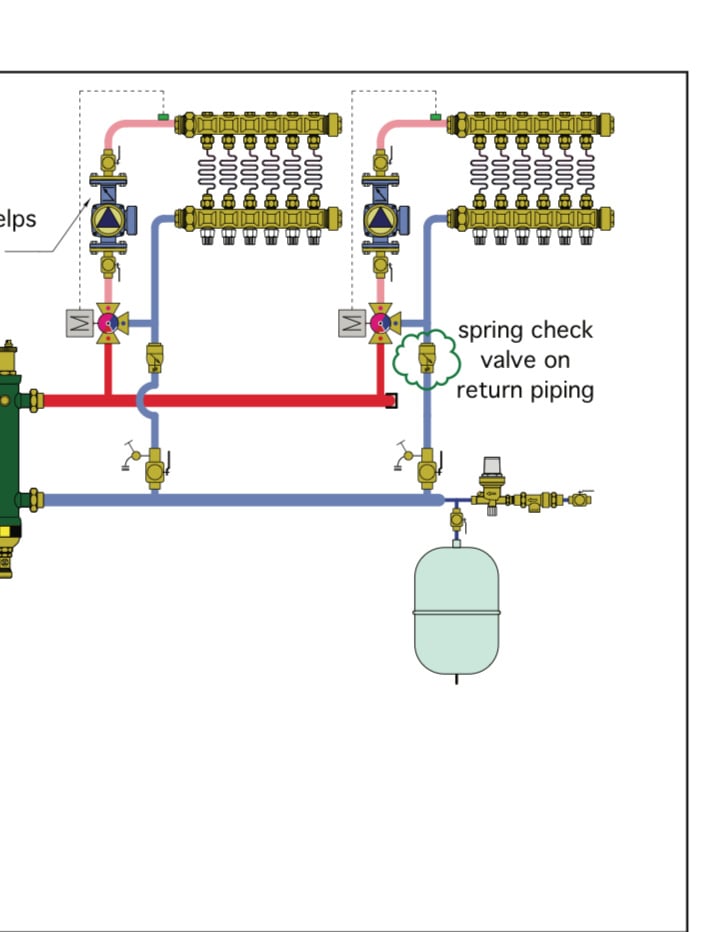
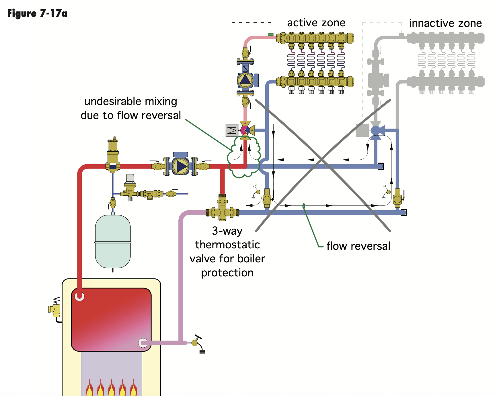
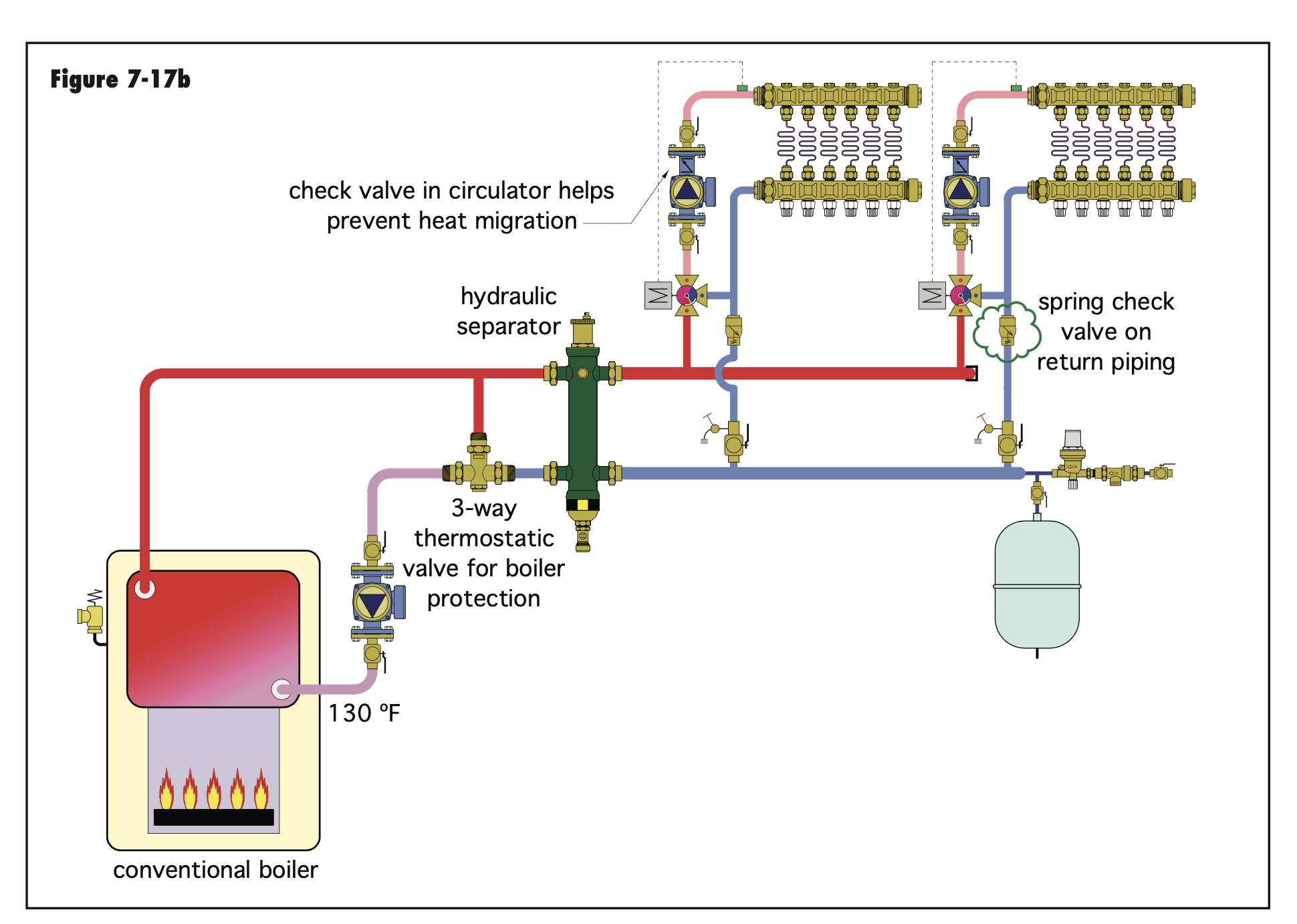
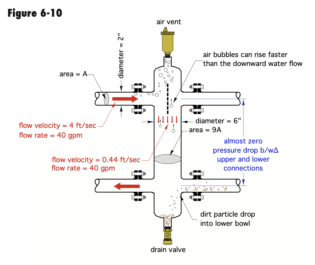
An example of a troubleshoot drawing below, not necessarily your system . In this case when the boiler protection valve is in a certain position, red port closed, the the pressure differential created by improper piping causes the reverse flow. Two issues here, lack of hydraulic separation, and the pressure differential pushing across the motorized 3 way valve.
In this case adding a hydronic spring check fixed the reverse flow. So the pump has a check, and the return has a check.
But with proper hydraulic separation it may not have needed both checks? Figure 7-17b
Best I can see you have proper hydraulic separation with the Navian header? Assuming everything is piped correctly.

 Bob "hot rod" Rohr
trainer for Caleffi NA
Living the hydronic dream1 -
I will look into the hydraulic separation question and get back to you. Yes my setup is a combi boiler so some of the piping is for DHW . . . .
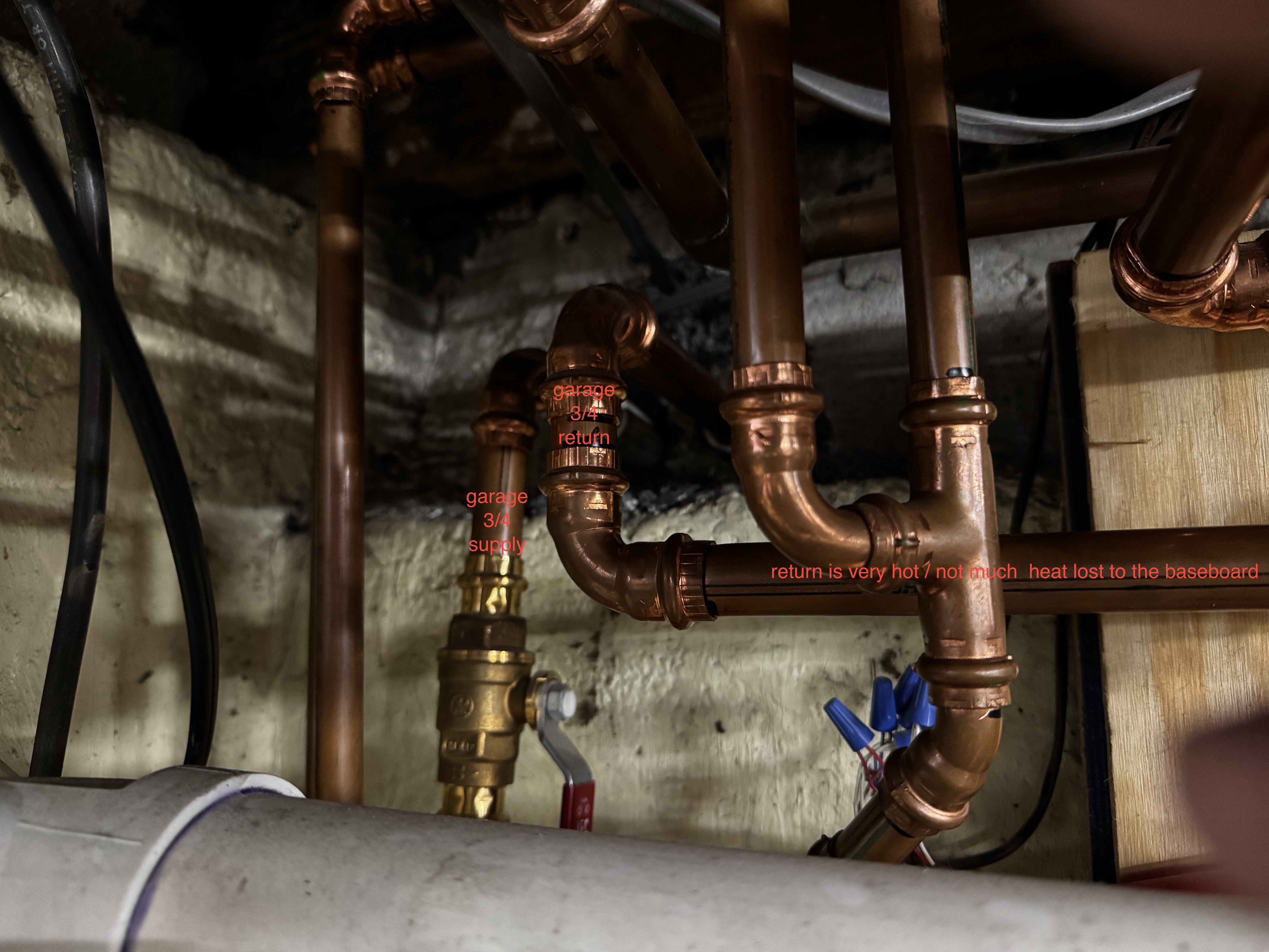
Ok, I have made some progress by rechecking some tweaks that I made earlier but that I thought didn't solve the issue. Previously I had shut off the garage "baseboard" (it's a baseboard radiator that hangs on the wall since space is so tight) loop because I thought that was creating a super low resistance and large capacity (it's 3/4 pipe) connection between supply and return and as such could create the reverse flow in the two loops that connect right into (or nearly right into) the baseboards large 3/4 return. It didn't seem to solve the issue though. Later I tried turning the porch zone's Taco 0015e pump level setting to the lowest and that didn't seem to solve the problem either.
Now, however, with both the porch zone pump on low AND the garage baseboard shut off (again the garage baseboard is on the porch zone) the reverse looping of the living room and 2nd floor west loops has stopped!
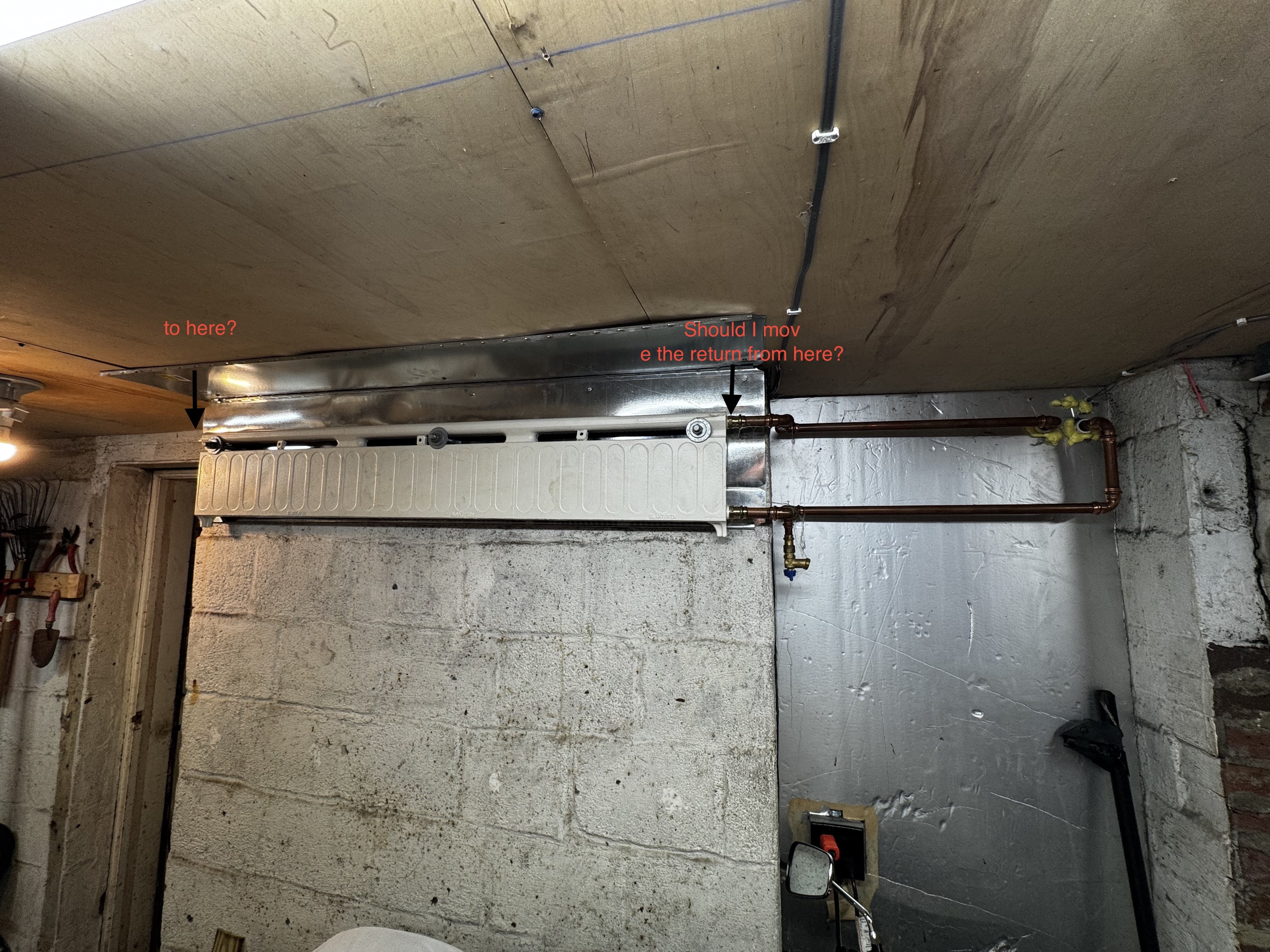
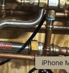
So I do think the problem is related to the piping of the garage baseboard. The idea for that baseboard was to just take the chill off of the garage and also benefit the heated porch space directly above so it isn't designed to truly heat the space to normal temps. I did notice when we first installed this system that only half of the baseboard was heating so clearly it wasn't piped correctly. The whole thing does eventually get hot but that is just due to the conduction of heat through the metal. Currently only the right half is getting water looped through it. I have attached a picture of how it is piped currently.
So with this new info, what changes might I make to allow me to keep the garage radiator working ( I will need to drain due to freezing issues it if I keep shut off for a long while) since I do feel that it is a good feature. I'm sure that piping it correctly so that the entire unit gets flow would help provide a bit more resistance. Does the mark up I made on the baseboard picture look like it will have it circulate properly? I suppose I could also simply close up partially the supply / return ball valves to reduce the flow to it some.
A more dramatic change would be to size it down to 1/2 piping and perhaps connect it into the stack somewhere else? I could cut the baseboard return before it reaches the Tee where it joins the radiant floors return and then tie it into the return stack somewhere lower maybe?
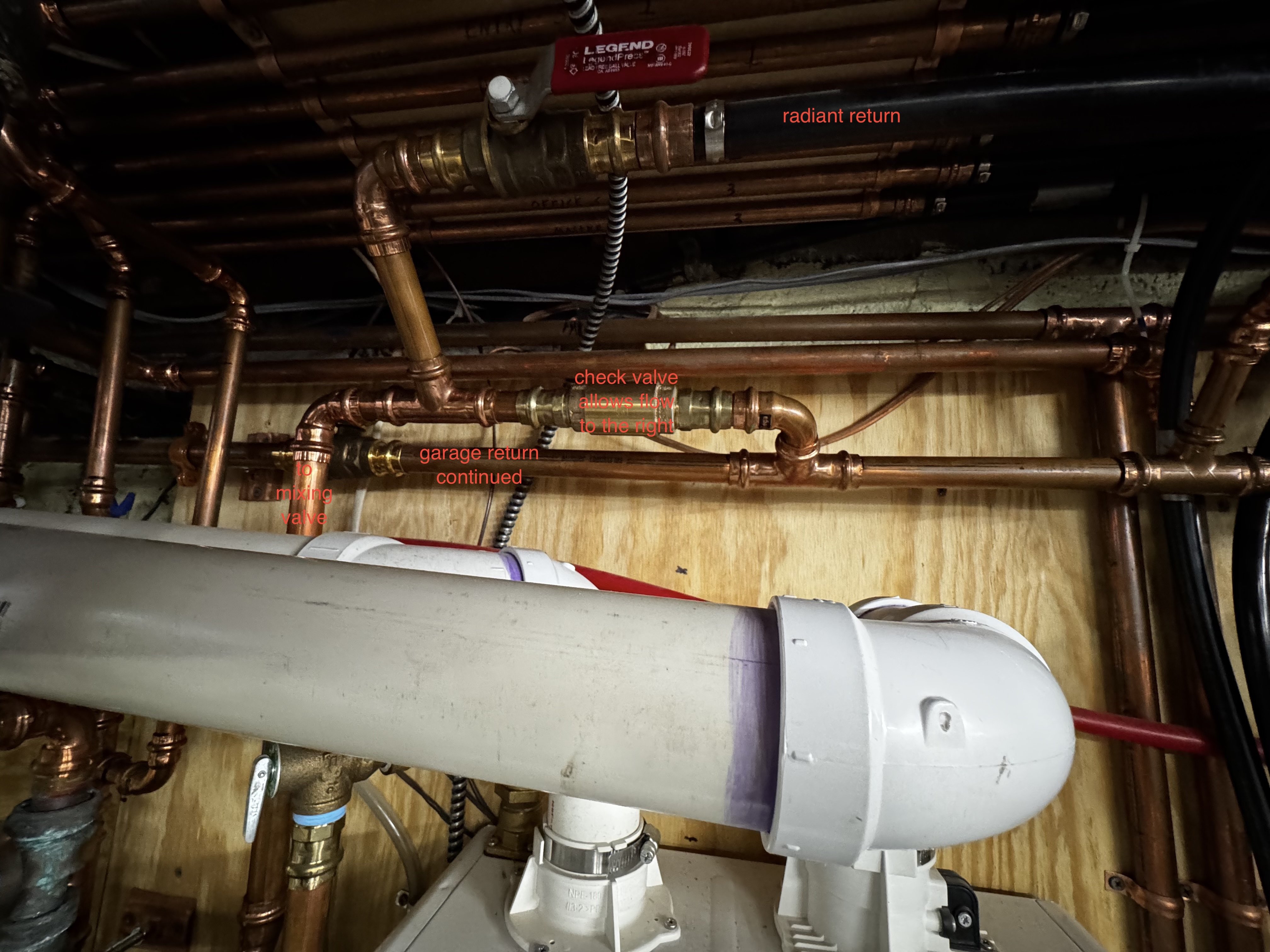
I will also reattach the pictures of the garage return as it travels over to the stack that I posted earlier. The orange text write ups on the pictures of the garage returns were from earlier so keep that in mind; they haven't been updated.

 0
0 -
Do you have the spec sheet for the radiator in the garage? It would show the preferred piping. It depends on how the tubes loop through it. Or it could have some air bubbles in it preventing the even heat output. If supply and return to the garage are the same temperature, it sounds like there isn't and flow through it? Which would explain why it is not warming across the entire length. Or it is mis-piped? :(
Actually that would be much better at the floor level. Baseboard convectors work by cold air entering the bottom, being heated and exiting the top. That is why they are called baseboard convectors.
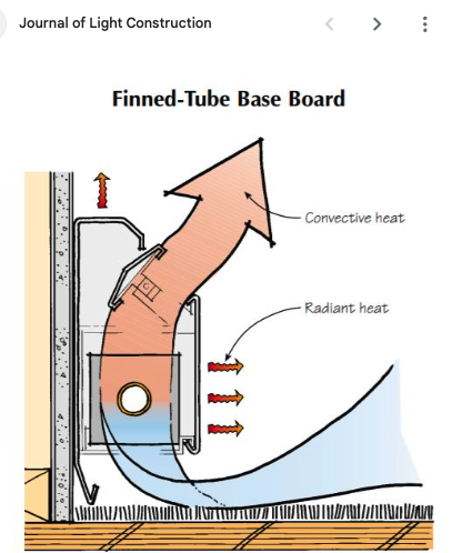
Up high like that it may just stratify the warm air up near the ceiling and not give you much output. That type of heater wants to see the coldest, floor level temperature ( blue color in JLC graphic) against the fins.
If the air entering the bottom is the same temperature as the air above it, it's basically constipated.
Maybe 20% of it's output is by radiation, so that is a plus. A small blower type or a wall mount kickspace heater is great for quick heat up, drying vehicles, etc.
\
You have valves up the ying yang, closing down the valve to the garage heat would have the same effect as downsizing the tube size.
I'm coming back to a mispiped hydraulic separator. The primary function of hydraulic separation is to allow zones, circuits to work with one another regardless of different or vastly different flow rates. You should be able to have a 3 gpm pump and zone right alongside a 1/2 gpm pump and zone and not get interference of flow crossing/ reversing.
I'm not a huge fan of those small tube size low loss headers the boiler people sell, the barrel, straight pipe really wants to be bigger, 3 times the diameter of the piping connected to it. But the main goal of the factory boiler headers is to assure the boiler gets adequate flow.
Read about separation here.
The only clear pic missing so far is of that header under the boiler and how it is piped.
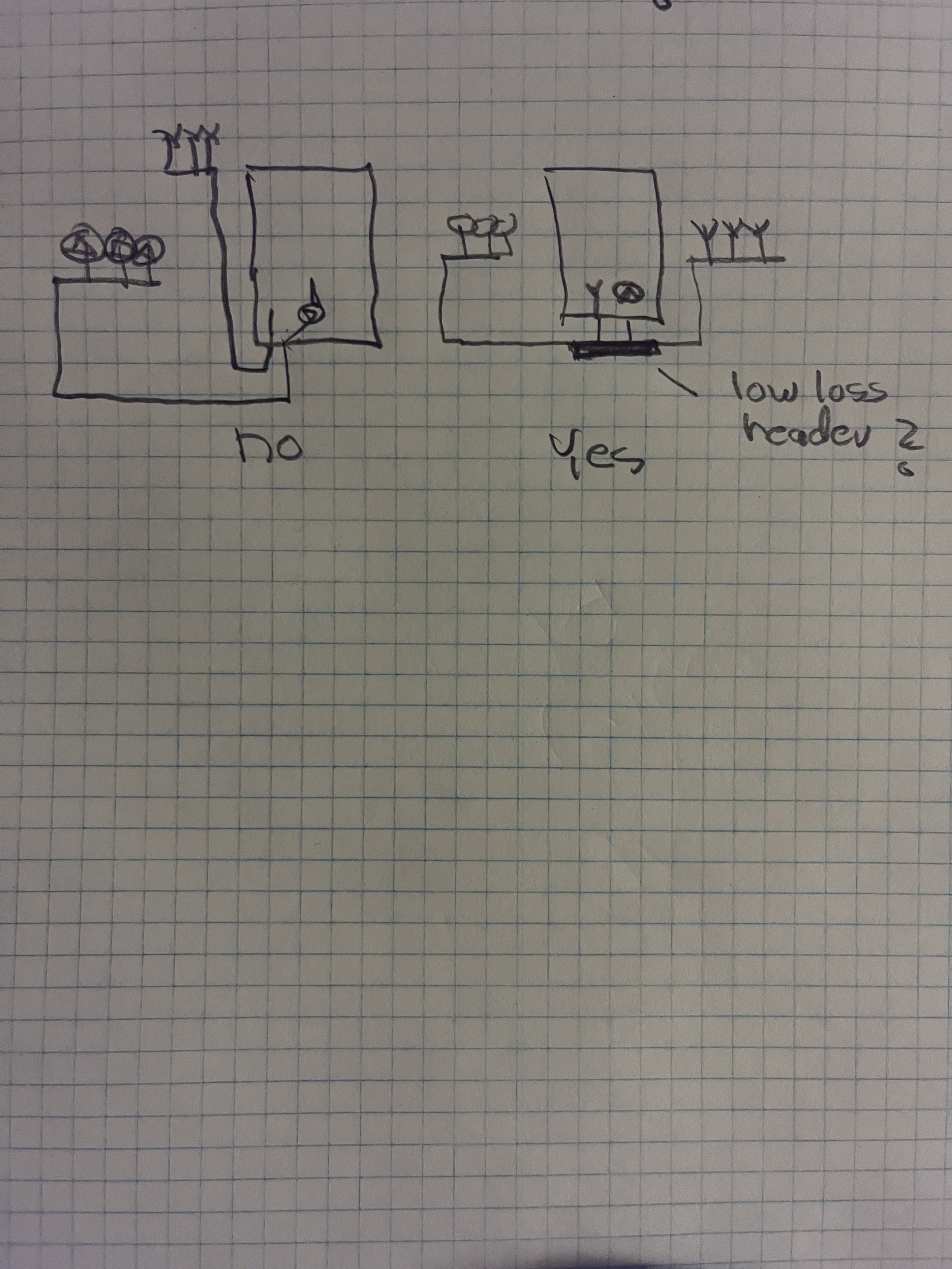
The header you have should look or function like the lower pic in fig 6-12 Mis-piped it could be the boilers pump is causing you unwanted flow issues?
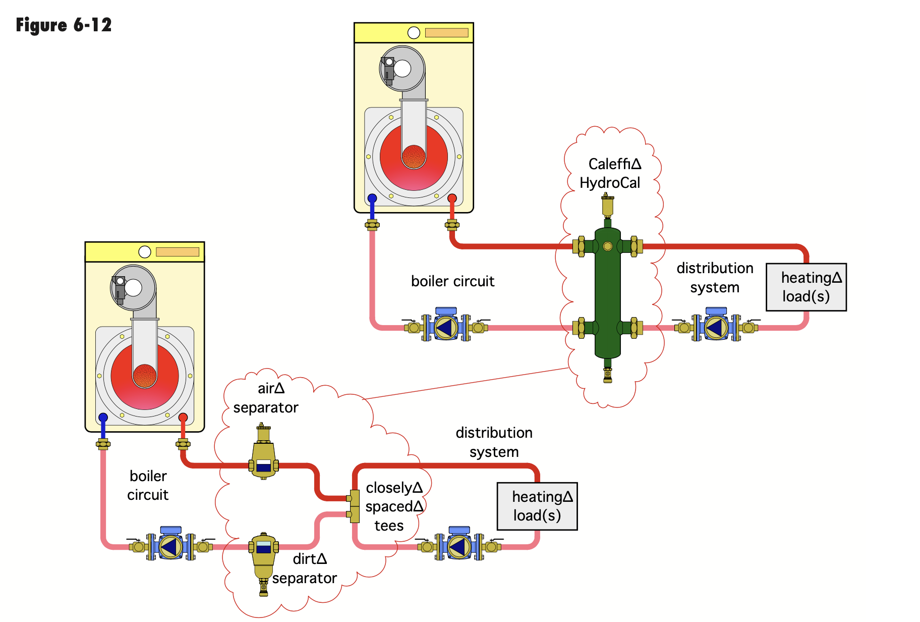
The common piping, headers, the copper where all the returns connect, and the copper where all the pumps connect on the supply side. That needs to be sized to provide adequate flow when every pump in the system is on and flowing. When those are undersized, that too can cause odd flow patterns. Those two copper "headers" are really an extension of the low loss header under the boiler. Looks like your headers are 1"?
If odd things happen only when all the zone pumps are running, I'd suspect under-sized common piping.
Some examples of how those headers should be "short / fat" or "generously sized" piping for all pumps to connect and get adequate flow.
 Bob "hot rod" Rohr
trainer for Caleffi NA
Living the hydronic dream0 -
Not to overwhelm you with science… These issues would be a good read for you and the installer.
A lot of the common piping/ control issues are addressed in these.
Issue 19 is also a good, after the fact, read. It goes over about 6 of the most common piping mistakes and fixes.
Bob "hot rod" Rohr
trainer for Caleffi NA
Living the hydronic dream0 -
I salvaged the baseboard heater from one of my jobs so I don't have any specs to know how it is piped. All I can say as it is piped now, the right half gets nice and hot really quickly (like it should) but the the water loops back at the halfway point. If I'm going to the trouble of repiping it, I might consider putting it down at the floor. I have too many motorcycles and my thinking was to get it up and out of the way, even if it isn't going to work optimally. Even at half capacity it does take the chill off of the room.
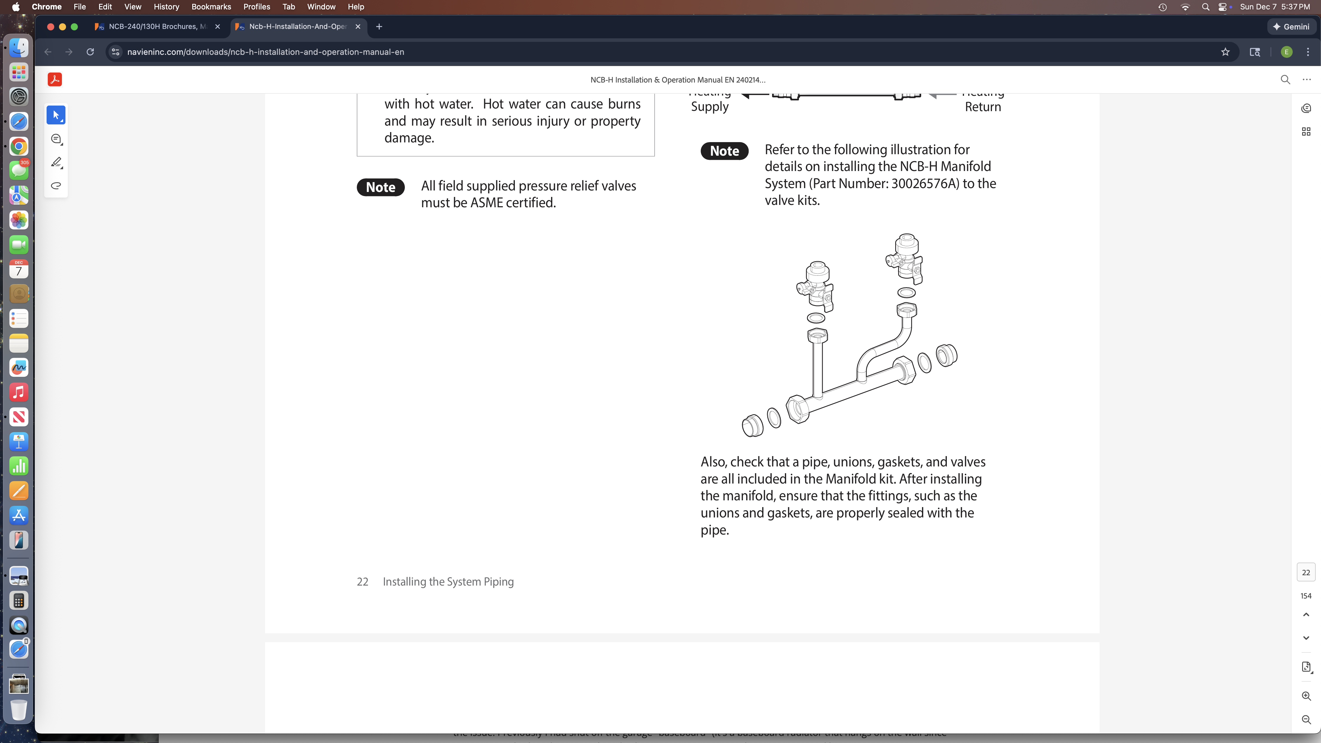
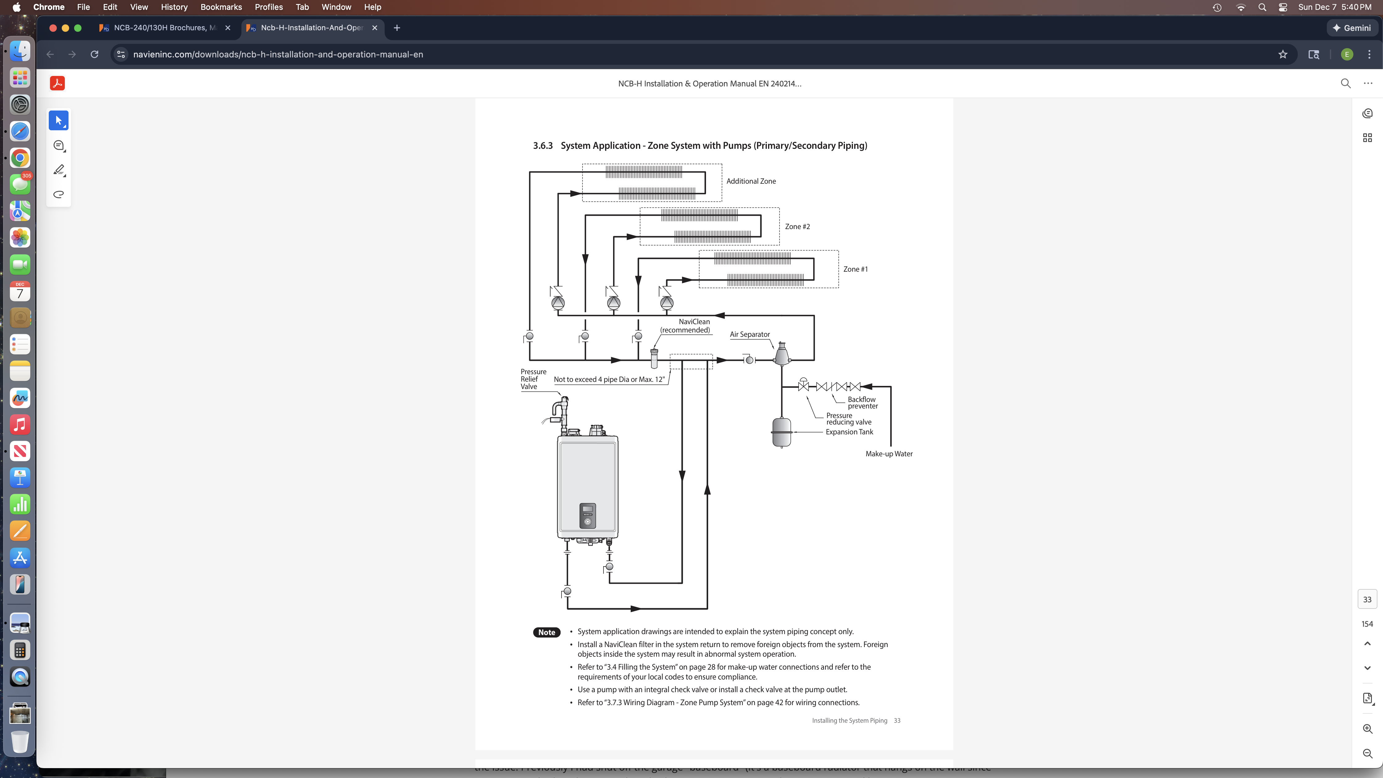
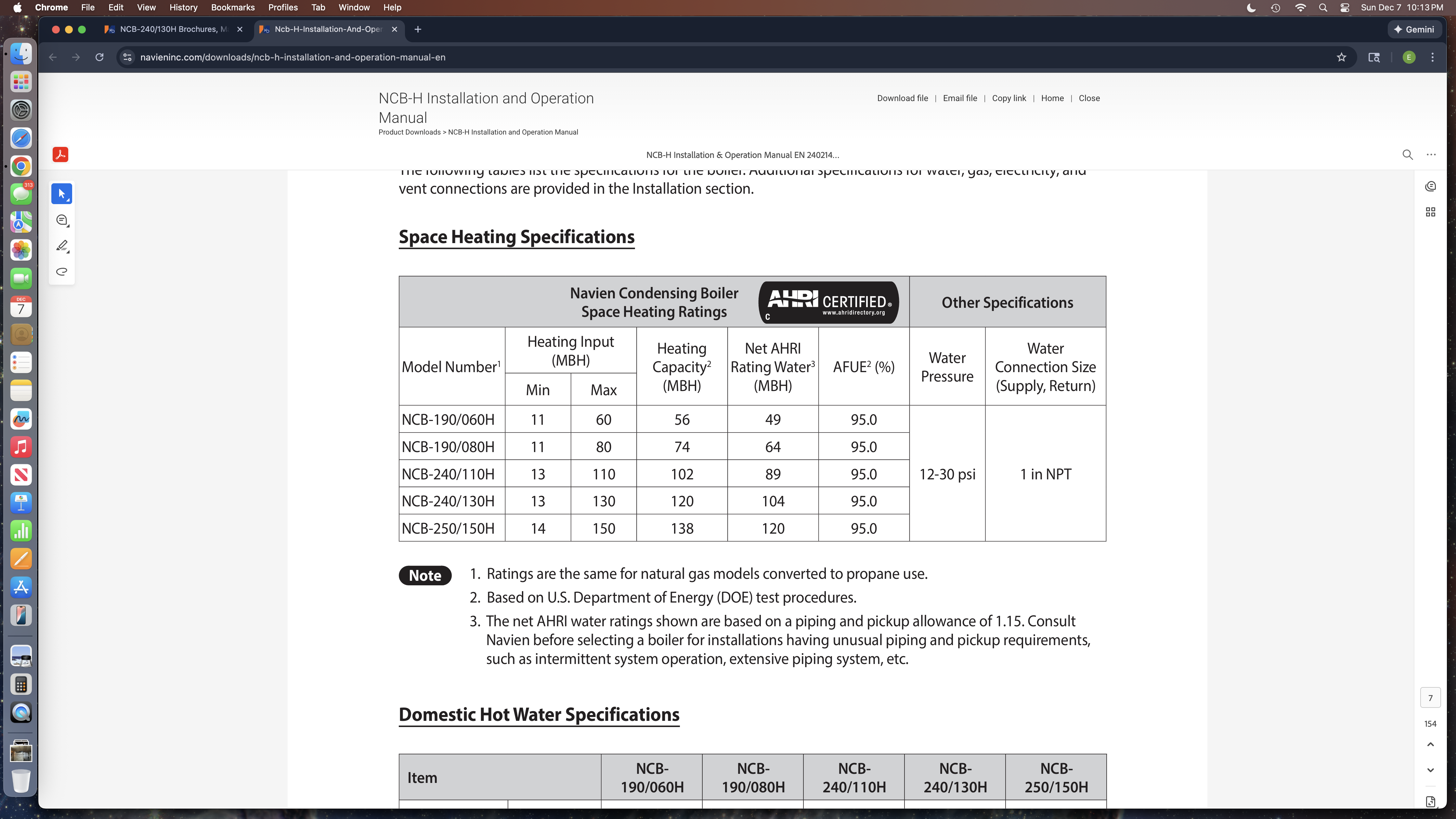
Here's a picture of the underside of the boiler. It uses Navien's proprietary manifold and there is no external hydraulic separator that I see. From what I can understand the manifold is designed to have the system work with either external individual zone pumps or zone controls. The Navien has it's own internal circulation pump. Here are some pages from the installation manual talking about their manifold and also how to connect up to a multiple pump type system. I don't see any thing going against what Navien shows but I don't really know.
From what I can understand about what is going on with my system is that the water currently coming from the the garage baseboard is large volume (almost no resistance in the radiator) and high temperature, making it like a continuation of the porch zone supply. The Living room loop (first floor zone) and the 2nd floor west loop (2nd floor zone) returns tap right into that 3/4 high volume, high temp pipe so when it the porch zone is flowing, those returns reverse and become supplies. Farther down the return stack / closer to the boiler the returns are behaving normally.

 0
0 -
Send a motorcycle to me, that frees up some floor space.
It looks like a steel or cast iron convector, so it could survive down at the floor. But this is the least of your worries now.
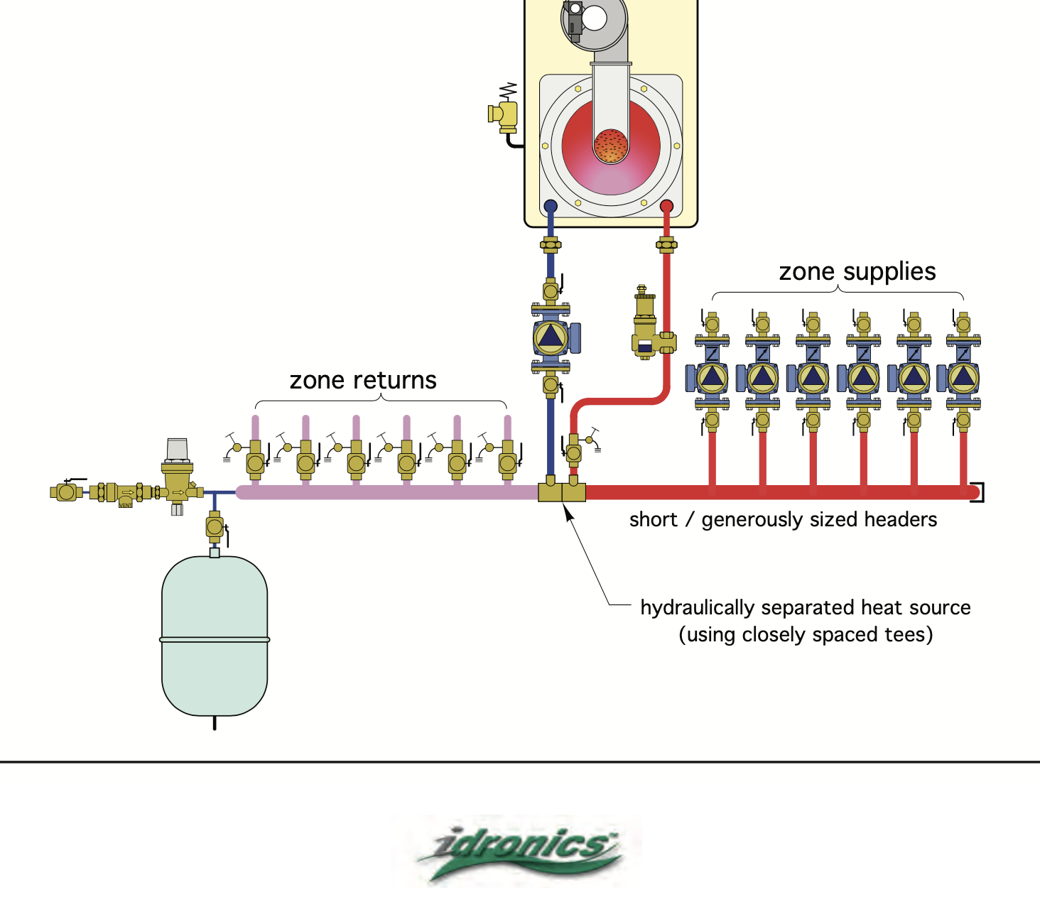
Here is what I'm talking about as far as adequate flow capacity.
I suspect the Navian header is 1-1/4" maybe larger. For a reason.
Yet it looks like it was reduced at both ends, maybe two sizes? and all the piping connected to it is down sized? I'd like to see all the loop piping be 1-1/4" copper, but 1" might get 'er done.
Navian supplies the union nut and tailpiece transition, I think someone else reduced it a size or two?
While manufacturers show piping diagrams, occasionally appropriate ones, they rarely put pipe sizes on the drawing. That comes down to the plumber installer.
Same as the electrician sizing wire and breakers. A carpenter sizing rafters, joists and beams.
I think you have a number of small design/ install glitches adding up. But not at the point of breaking out the sawzalls, yet. Keep snooping, trying different combination.
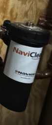
First time seeing the NaviClean, has that been blown down or disassembled and cleaned? It could also reduce loop flow, starve pumps so they try and pull from one another. It too looks a bit undersized by the piping connections. It may have a bypass valve built in to allow you to pull it apart without a draindown.
 Bob "hot rod" Rohr
trainer for Caleffi NA
Living the hydronic dream0 -
The NaviClean looks like a re-labeled Adey. The sample I have has small port size. They don't list any Cv values. Which can sometimes be an indicator….
Bob "hot rod" Rohr
trainer for Caleffi NA
Living the hydronic dream0 -
We actually had a service over the summer and the installer cleaned the Naviclean. There wasn't much in there. It is designed to be cleaned easily; you can see the plastic cap wrench for it hanging on the wall next to it. There are two isolation valves, you shut them off, open the cap and clean the magnet. Yes it says "powered by Adey" right on it.
All the piping coming off the Navien manifold is 1" copper (1.125 OD). It is 1" up to the zone pumps and 1" down the return stack. Says right in the install manual that the space heating water connections should be 1 inch so hopefully we can lay that to rest. Yes the manifold is something like 1.5 inches OD and the pipes that go into the boiler for the return and supply are about 1" od. EDIT: Now that I think of it. Navien is probably talking about the actual connections at the boiler rather than the recommended loop size.
My installer is Navien trained and although he certainly isn't above error, I don't think the main loop plumbing is undersized, at least according to Navien.
As to the baseboard, I will need play around with it and maybe a garden hose to see how it is piped and or if it is blocked somehow. All I know is at this point it seems to flow fine for the right half.
I think my next step is to gradually open up the garage flow to the point where the radiator gets hot but hopefully not enough to start the reverse flowing.
If no go then maybe try repiping the garage radiator so that it flows properly and also fixing the mixing valve supply.
If no go then it's time for check valves I suppose.
 0
0 -
Right now I have it working (since last night) with the garage baseboard just partially open on the ball valve shutoff. It's heating and for the moment each zone's temp is the same as it's thermostat. Seems like success but I will have to give it more time.
0 -
Following up, I have a workable solution for now. If I really choke down the garage baseboard, I can keep the 1st floor living and 2nd Floor west loops from reversing. It's not ideal because the garage baseboard isn't heating up nearly as much as before but for now it won't freeze up and everything else works properly.
The baseboard in the garage is cast iron and made by slant fin. I think it's their "Rhino Cast". I found some install instructions and it looks like the supply and returns should be on the bottom fitting on opposite sides from each other, although I am not sure if it would work just a well going into one top fitting and out the bottom fitting on the opposite side. The bleeder valve goes on the return end upper fitting of course.
Anyways, I appreciate all the help so far. I'm going to eventually make the changes to the mixing valve and rework the garage piping. I'll probably lower the radiator to the ground at the same time. I do think that my idea of cutting the garage return pipe off before the tee with the radiant floor return and connecting it in with 1/2 piping to the return stack at the bottom will improve / solve the issue. If not then it's time for check valves. Replumbing the supply and return stacks to a larger diameter 1 1/4 isn't a practical solution.
PS, Naviclean is clean and unblocked; I checked it.
 1
1

Categories
- All Categories
- 87.6K THE MAIN WALL
- 3.3K A-C, Heat Pumps & Refrigeration
- 59 Biomass
- 429 Carbon Monoxide Awareness
- 124 Chimneys & Flues
- 2.2K Domestic Hot Water
- 5.9K Gas Heating
- 119 Geothermal
- 168 Indoor-Air Quality
- 3.8K Oil Heating
- 78 Pipe Deterioration
- 1K Plumbing
- 6.6K Radiant Heating
- 394 Solar
- 15.9K Strictly Steam
- 3.5K Thermostats and Controls
- 56 Water Quality
- 50 Industry Classes
- 50 Job Opportunities
- 18 Recall Announcements