Tekmar 360 Control- Assistance Needed
Comments
-
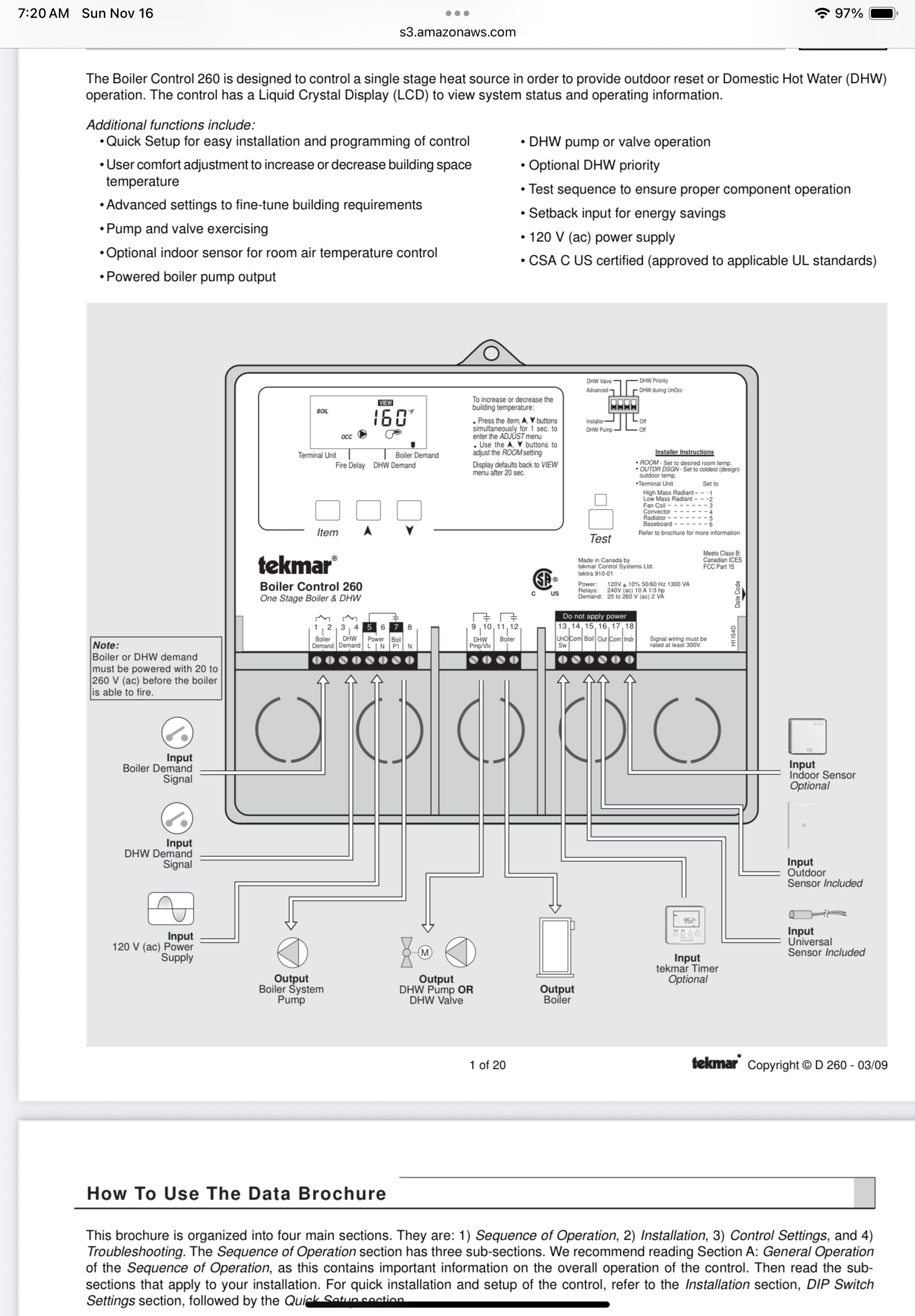
Sorry about that, I have a 260 here at my shop that I was looking at. It has the DHW function
 Bob "hot rod" Rohr
trainer for Caleffi NA
Living the hydronic dream0 -
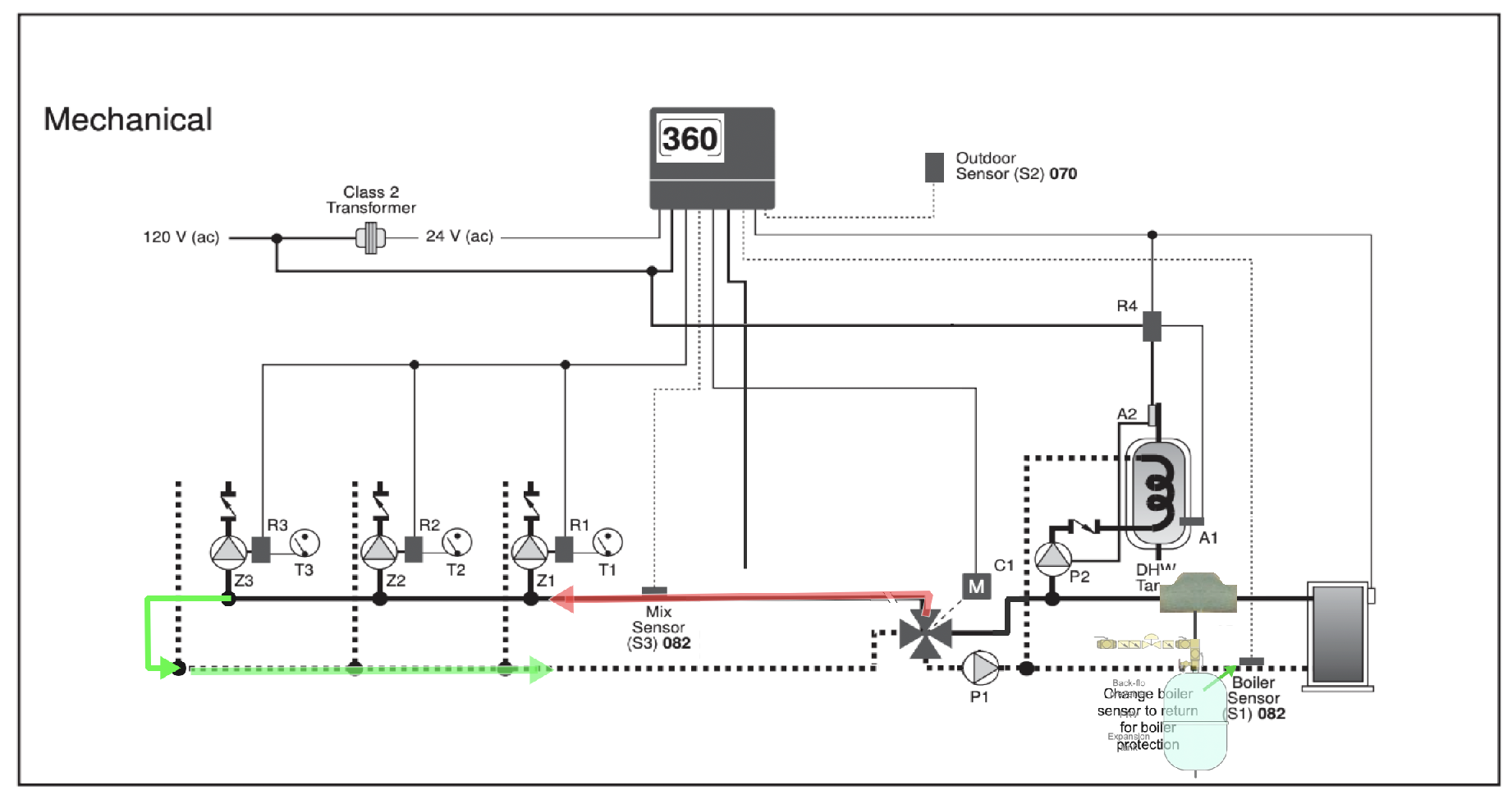
Every time I look closer at the piping I see something else. The P1 Pump is piping through a loop that starts at the 4 way valve and continues past each Zone pump and zone return then returns to the 4 way valve. (Green pipes) I did not see that before. Red pipes represent mixed (lower temp) supply to the zone loop
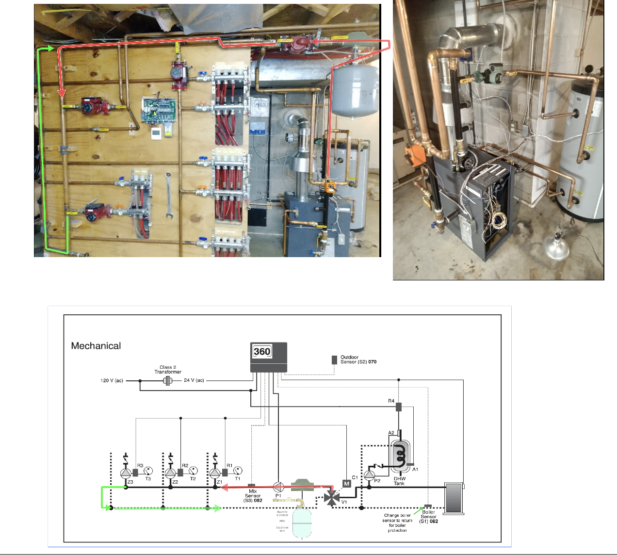
This makes more sense to me now. Good design, I still believe that the boiler sensor should be on the return pipe to the boiler for boiler protection
Edward Young Retired
After you make that expensive repair and you still have the same problem, What will you check next?
0 -
There is no clear definition for adding that additional P-1 pump. Which I see in series with the 3 zone pumps, essentially doubling the head. I suppose adjusting the manifold valve regardless. This talks about the addition pump in the boiler loop, I think the same applies to the secondary, or mixes side of the valve.
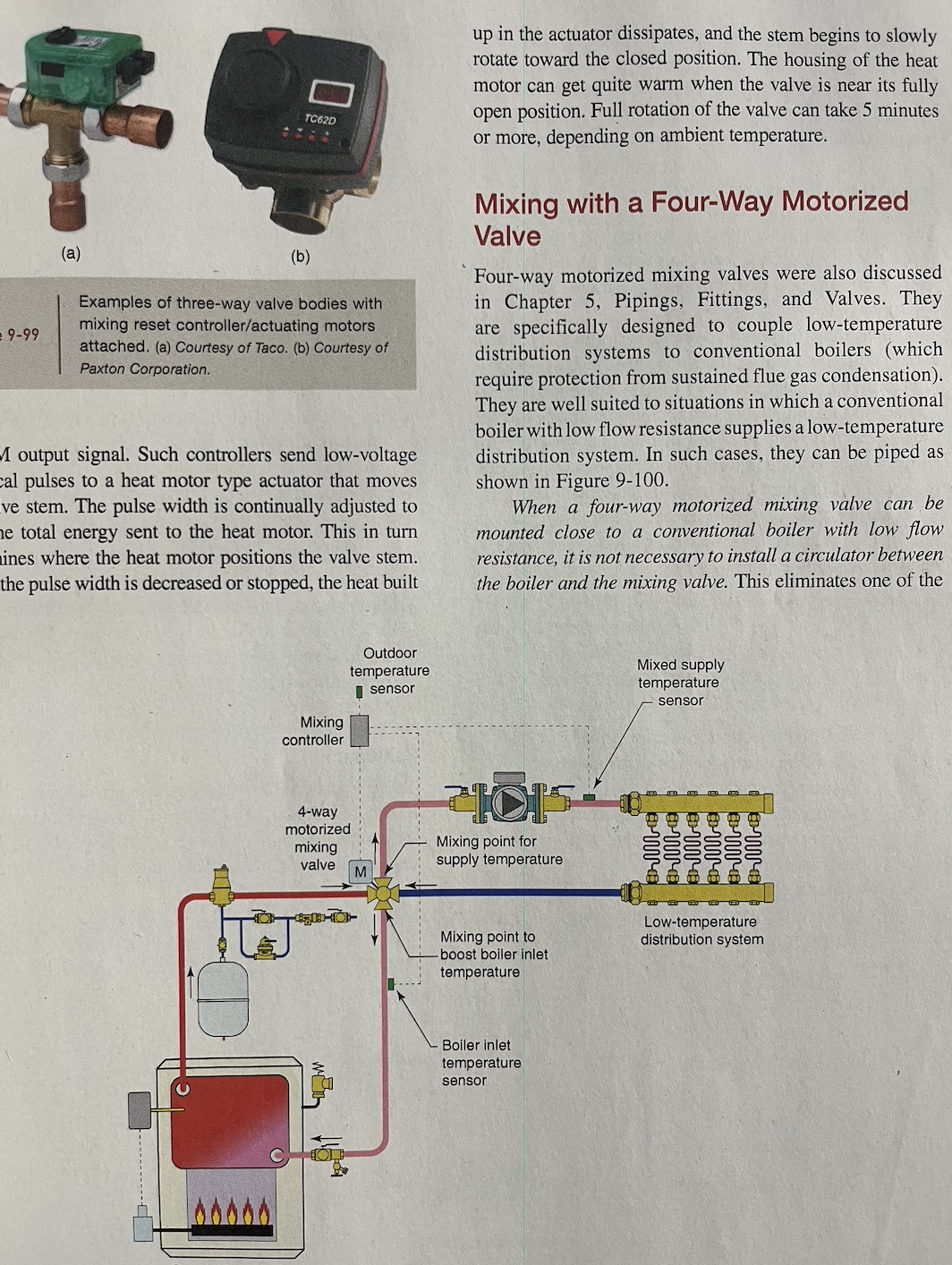
It will be easy enough to try it both ways, with P-1 running or not. Watching the flowmeters would be an indication of what change it makes.
It's been years since I did these 4 way mix. I embraced the condensing boilers early on, never looked back. I don't recall adding that P-1. Although many were piped off a P/S series loop with close tees.
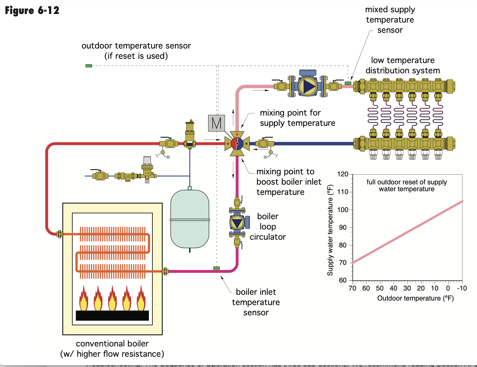
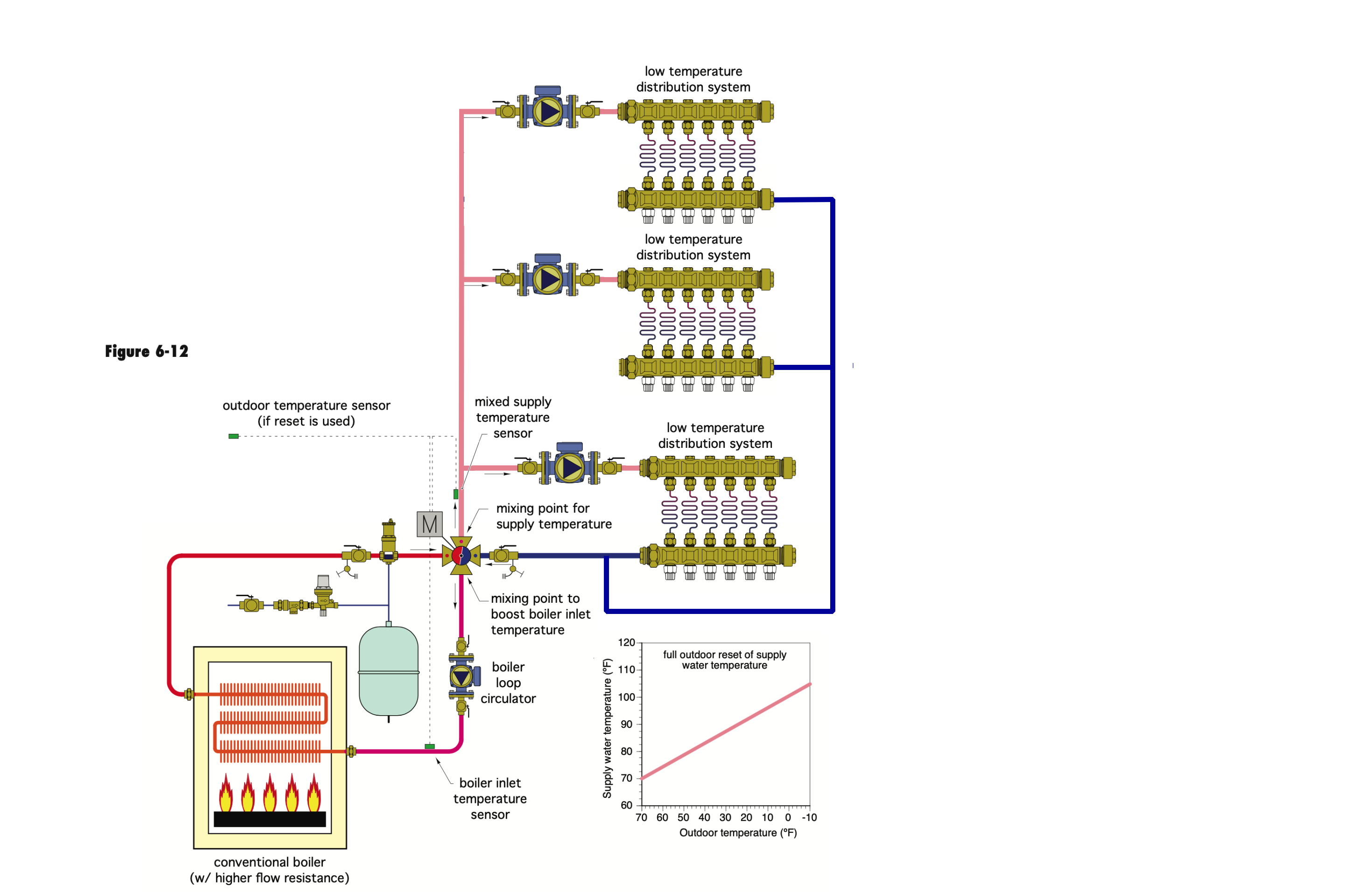
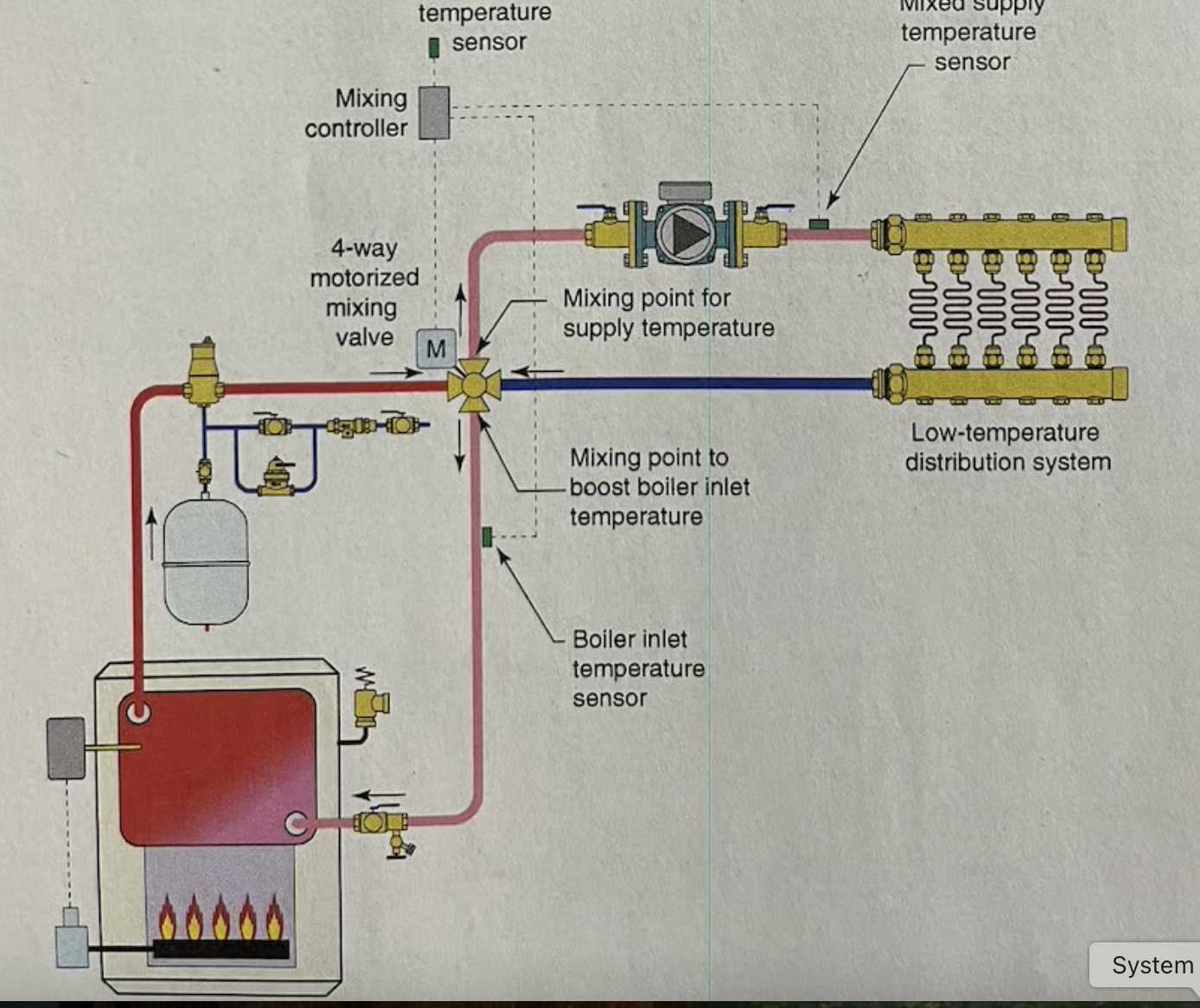
It seems that IF I thought an additional pump was required for adequate boiler flow, it would be in the boiler loop? Fig 6-12 Either way I see pumps in series.
I agree the sensor on the return, the manual shows and explains the various locations. The system supply sensor just before the first zone pump.
Bob "hot rod" Rohr
trainer for Caleffi NA
Living the hydronic dream0 -
@hot_rod said: "There is no clear definition for adding that additional P-1 pump. Which I see in series with the 3 zone pumps, essentially doubling the head."
Actually with the supply and return connected after the last zone pump and before any of the zone returns, the P1 pump is not actually in series. I just saw that piping arrangement this morning for the first time. See the diagram and photo from my most recent post.
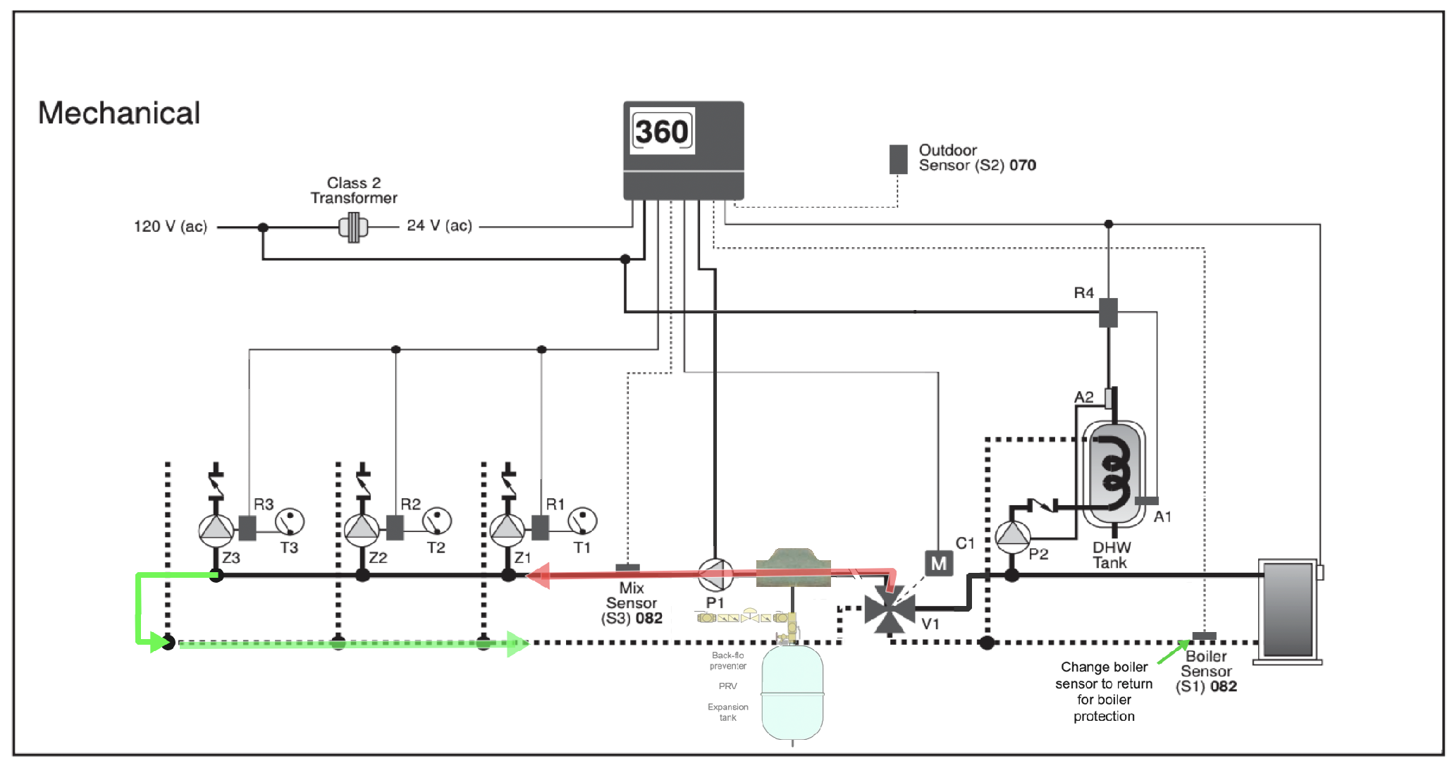
But without a boiler pump I can't see how boiler protection will work if there is no boiler pump to cause flow thru the boiler independent of the P1 system pump. That boiler might get to 180° limit temperature trying to maintain a 130° minimum return temperature. Is there a way around that as it is currently piped Bob?
Edward Young Retired
After you make that expensive repair and you still have the same problem, What will you check next?
0 -
If you connect the loop, are the pumps in parallel. Head stays the same
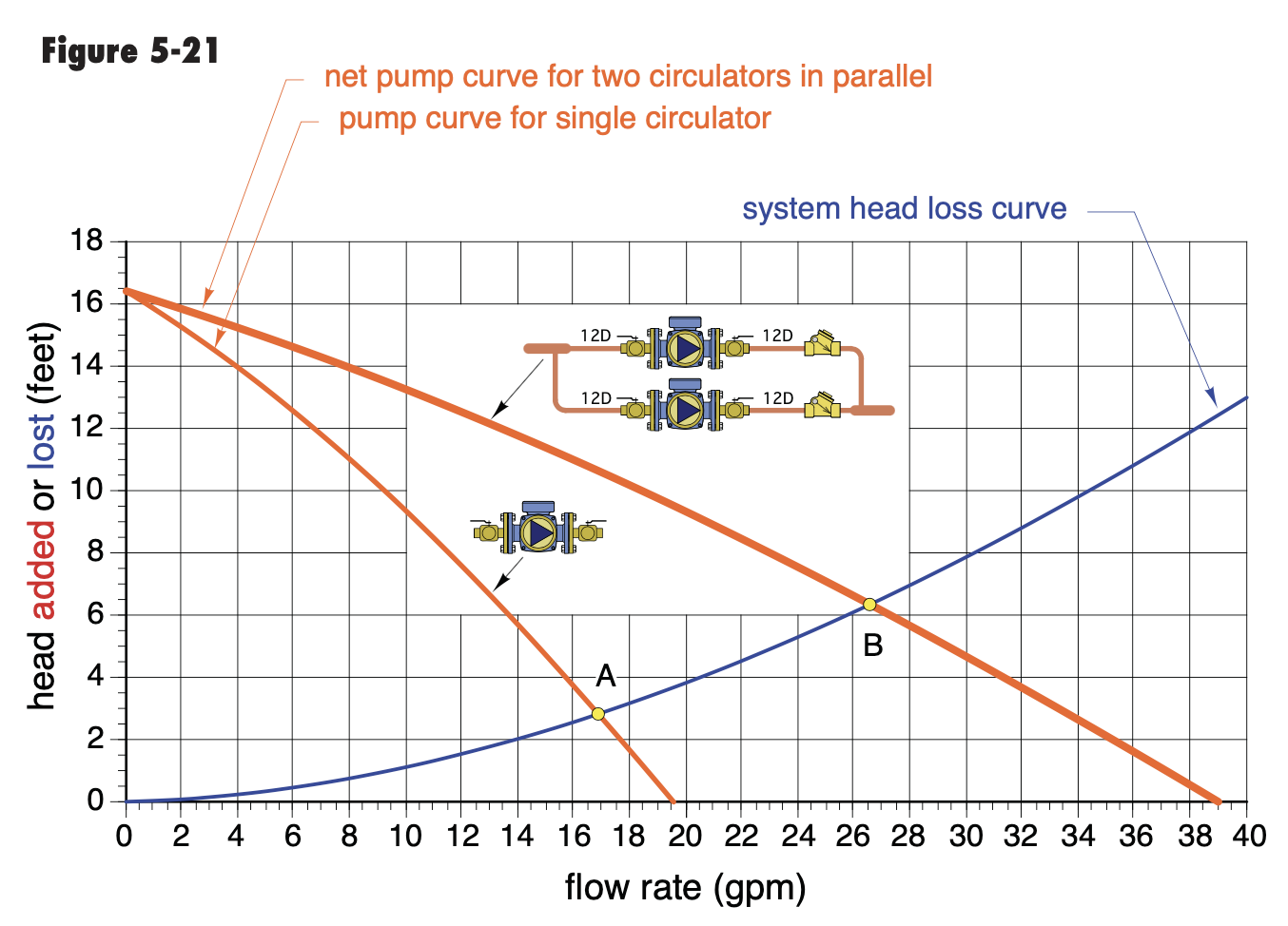
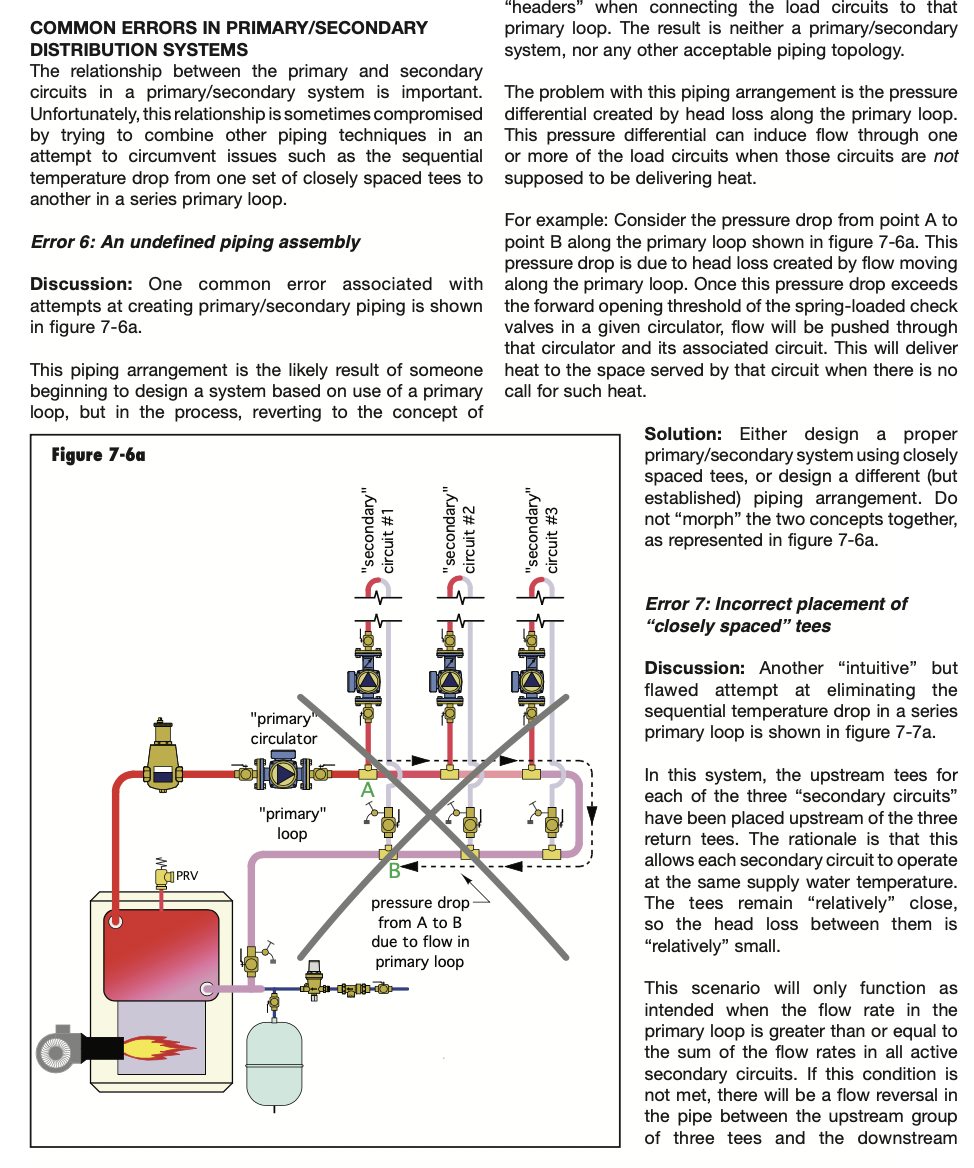
flow doubles. I think the zones would want to be taken off closely spaced tees?
I would make sure zone pumps are checked.
Or this potential
At this point the system is piped, fire it up, see if it does what is expected. Hydronics is a somewhat forgiving playground. Every hydronic system has different flow dynamics based on the piping/ pumping relationship.
It's possible the control never lets the 4 way close off either side completely, so enough flow across the boiler to keep the sensor response. I know the early vane type mixers were not a 100% bubble free seal.
Will that boiler handle a no flow condition? Is it tankless coil enabled? If there is no flow the boiler is hot and isn't seeing cool return?
Bob "hot rod" Rohr
trainer for Caleffi NA
Living the hydronic dream0 -
Would this be better?
Move the air separator and PONPC to the hottest pipe on the on the system and move the circulator pump to the outlet of the mix valve to the boiler return. this would be in fact pumping away from the PONPC by all the circulator pumps thru the 4 way valve?
Edward Young Retired
After you make that expensive repair and you still have the same problem, What will you check next?
0 -
I'd prefer the purger at the hottest point, If it were a microbubble type it would get the job done most anywhere in the system.
I would still be inclined to run it as is, before changing things.
I know we ran many systems like this, and this drawing still shows up in some boiler manuals. I think I attached those early on in the other threads.
I don't recall if these are low, high or medium mass radiant zones. It's really only the high mass slabs that have the potential to pull the return down.
There is some rule of thumb, if the low temperature high mass zone is 10% or less of the boiler output, it probably will not pull the boiler down for excessive time.
 Bob "hot rod" Rohr
trainer for Caleffi NA
Living the hydronic dream0 -
Again thanks for all the replies and diagrams! My hvac friend stopped by yesterday as he wanted to put eyes on the setup once again. Armed with the diagrams and alot of muttering under his breath he smiled!
The relay, decided to go with a Taco switching Relay as it is already in an enclosure and the $ was not much more.
As an aside the coal stoker boiler has been sold.I stripped it down the other day and it is due to be moved out this afternoon.
0


Categories
- All Categories
- 87.6K THE MAIN WALL
- 3.3K A-C, Heat Pumps & Refrigeration
- 59 Biomass
- 430 Carbon Monoxide Awareness
- 124 Chimneys & Flues
- 2.2K Domestic Hot Water
- 5.9K Gas Heating
- 120 Geothermal
- 168 Indoor-Air Quality
- 3.8K Oil Heating
- 78 Pipe Deterioration
- 1K Plumbing
- 6.6K Radiant Heating
- 394 Solar
- 16K Strictly Steam
- 3.5K Thermostats and Controls
- 56 Water Quality
- 51 Industry Classes
- 50 Job Opportunities
- 18 Recall Announcements