Tekmar 360 Control- Assistance Needed

I am in the process of installing our new Weil-McClain CGa3 with indirect dhw. This is taking the place of the coal stoker boiler that is used for our radiant floor heating.
All the piping is done and no leaks! Though I did touch my forehead on a hot pipe!
So I do have a Tekmar 4 way mixing valve with the Actuator. But I was wondering if they is anyone who could talk me through the 360 controller.
Would like,if possible, to do a phone call.
Thanks!
Tom
Comments
-
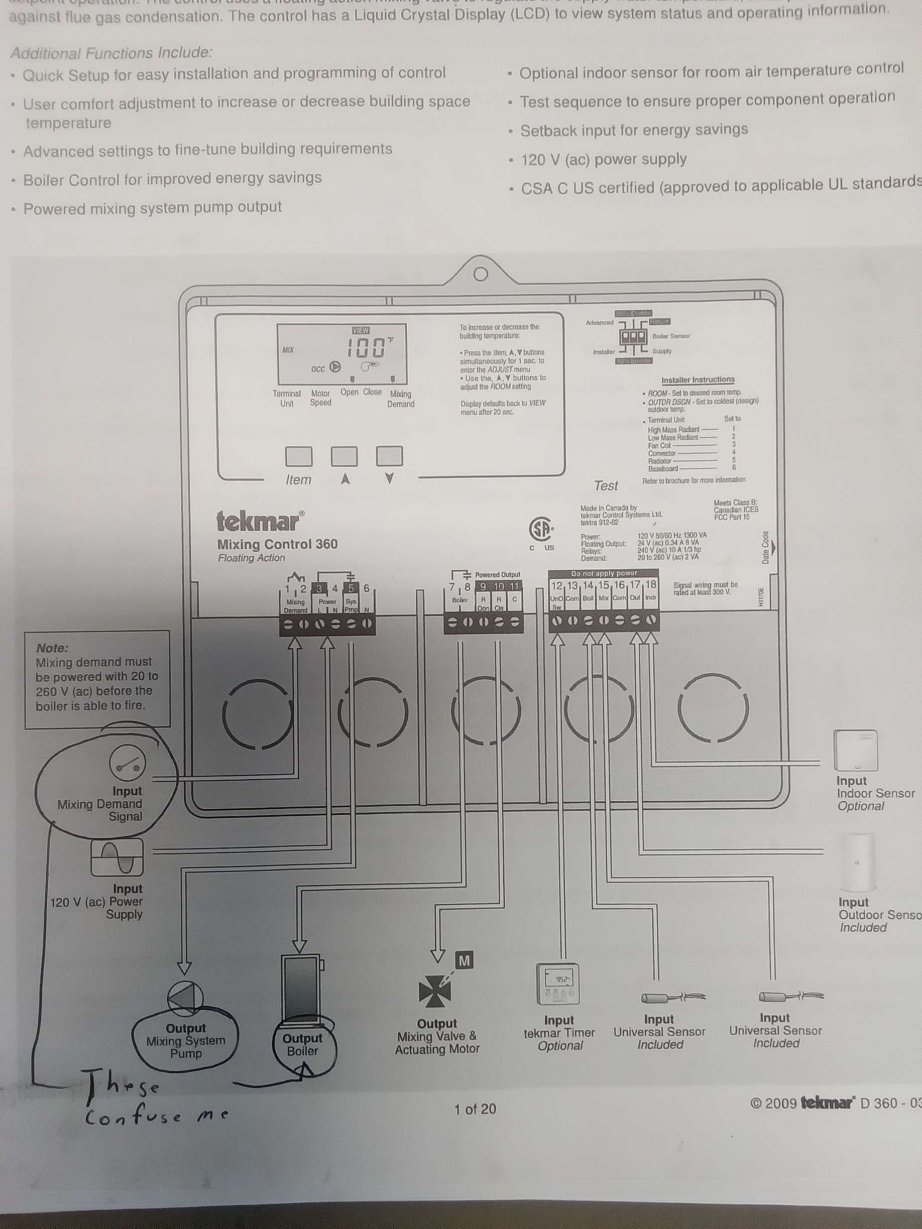
I have no installed a 360 but I have red the manual. Tekmer has a unusual diagram in the cover of the instruction sheet
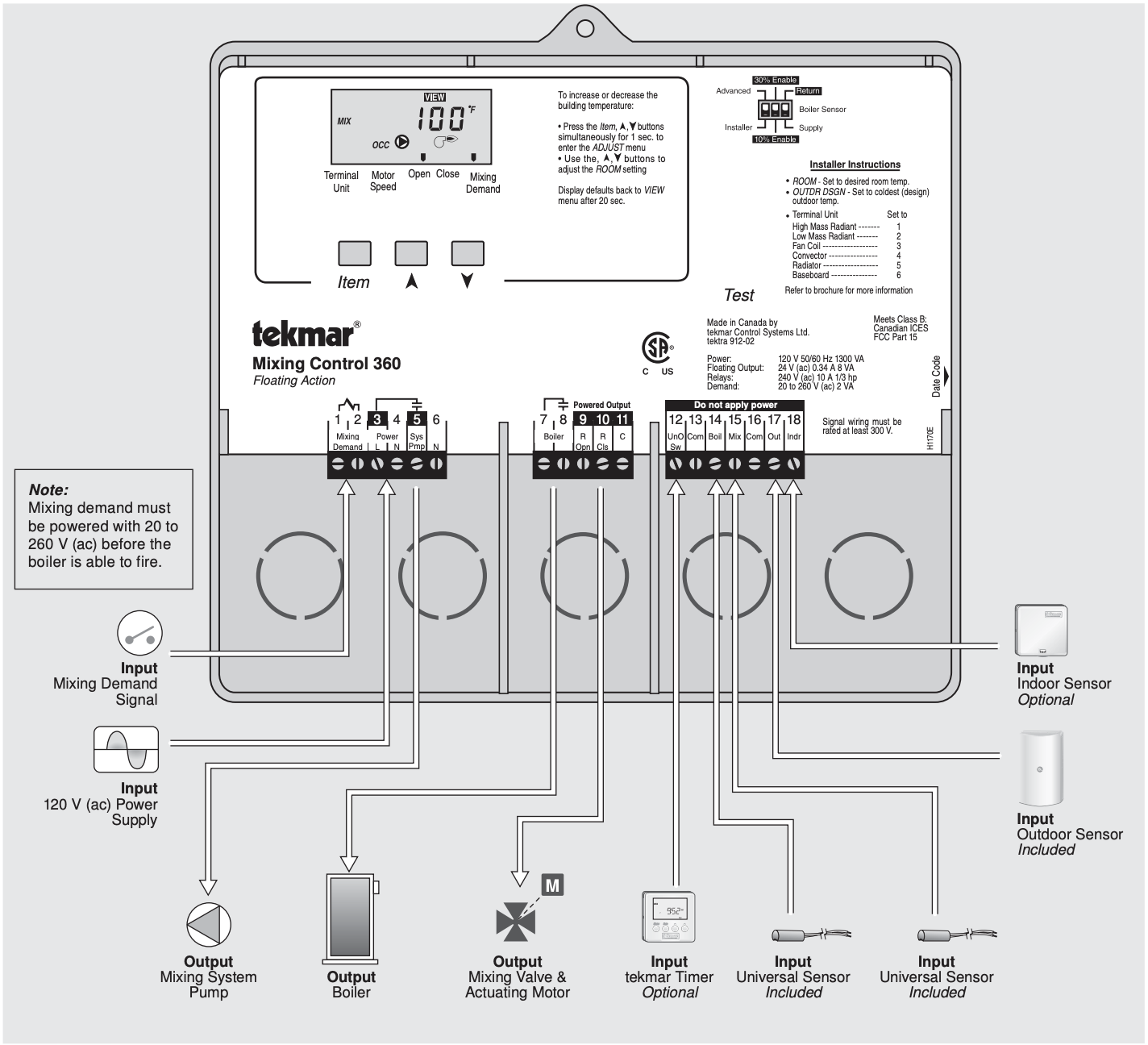
It is not exactly a wiring diagram but more of a flow chart of what the control can connect to. If you look at the actual text inside the I/O manual you will see that the terminal 1 and 2 that shows a thermostat connected in the above diagram (what ther are calling a Mixing Demand is not actually a place to connect the thermostat but a place that needs some voltage to power the control with as little as 24 VAC or as high as 240 VAC. Crazy right?
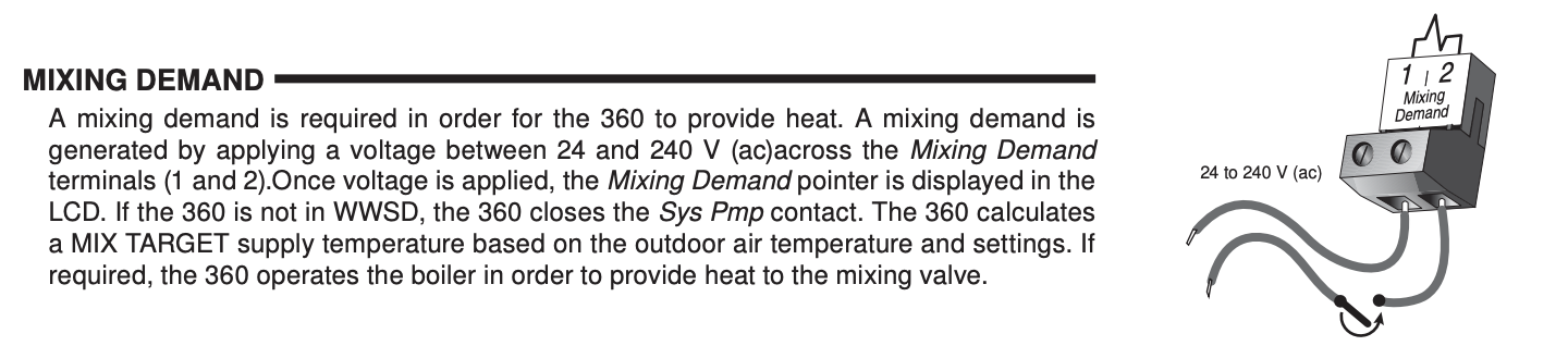
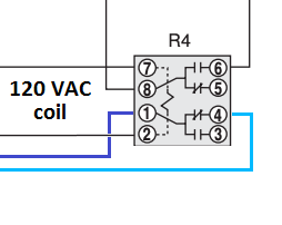
So this detail from page 5 shows some kind of switch (like a room thermostat) that will let 24v. to 240v.power that coil that is between the 1 and 2 wire terminal inside the 360.
I would recommend that you read that manual at least 3 times until you get to understand exactly what the manufacturer is telling you.
On page 10 you will see the actual wiring connections as the manufacturer intends you to connect them. I find that referinf to the illustration of the cover and each indivicual component connection on page 10 and 11 is helpful. But i still had questions the first time I connected a Tekmar to the system I was installing.
Edward Young Retired
After you make that expensive repair and you still have the same problem, What will you check next?
0 -
I find Tekmar pretty easy to figure out usually. Sometimes there terminology gets in the way
0 -
What I find that helps with tekmar sometimes is to look at their application guide
 1
1 -
Usually you can find someone that has done a You Tube video on connections or programming. Or at the tekmar site itself.
What are you stuck on specifically?
Bob "hot rod" Rohr
trainer for Caleffi NA
Living the hydronic dream0 -
I will make sketch of our system , and post it, then I will ask a few questions.
In the meantime I will reread the manual again and again!
0 -
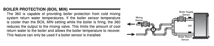
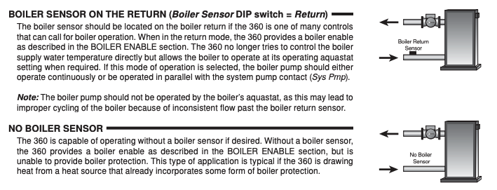
First step, get all sensors wired, and placed according to what you want them to do.
The boiler sensor location gets confusing. Here are the options for where that gets placed depending on your goals. If boiler protection is your priority, use the first drawing, sensor on the return pipe at the boiler.
 Bob "hot rod" Rohr
trainer for Caleffi NA
Living the hydronic dream0 -
I was wondering how best to secure the sensor to the copper pipe? Thinking of some pipe insulation?
0 -
I usea small stainless hose clamp. Yes insulation over it. A chunk of fiberglass even if you don't have pipe insulation.
The tekmar sensors have a small dish groove in the sensor so they fasten to pipe well.
You can change and adapt if the system doesn't do exactly what you want the first attempt.
Write down the settings as you make them to keep track of what change makes what difference.
I imagine many controls go in with factor default settings, no one comes back to fine tune it to the exact application. So for the homeowner to learn settings and adjustments really maximizes what the control can do for you.
I just bought an EV truck, it may take the rest of my life to figure out all the settings and options, which they update on a weekly basis!
Bob "hot rod" Rohr
trainer for Caleffi NA
Living the hydronic dream1 -
I have a F150 and the manual is 500+ pages long!
0 -
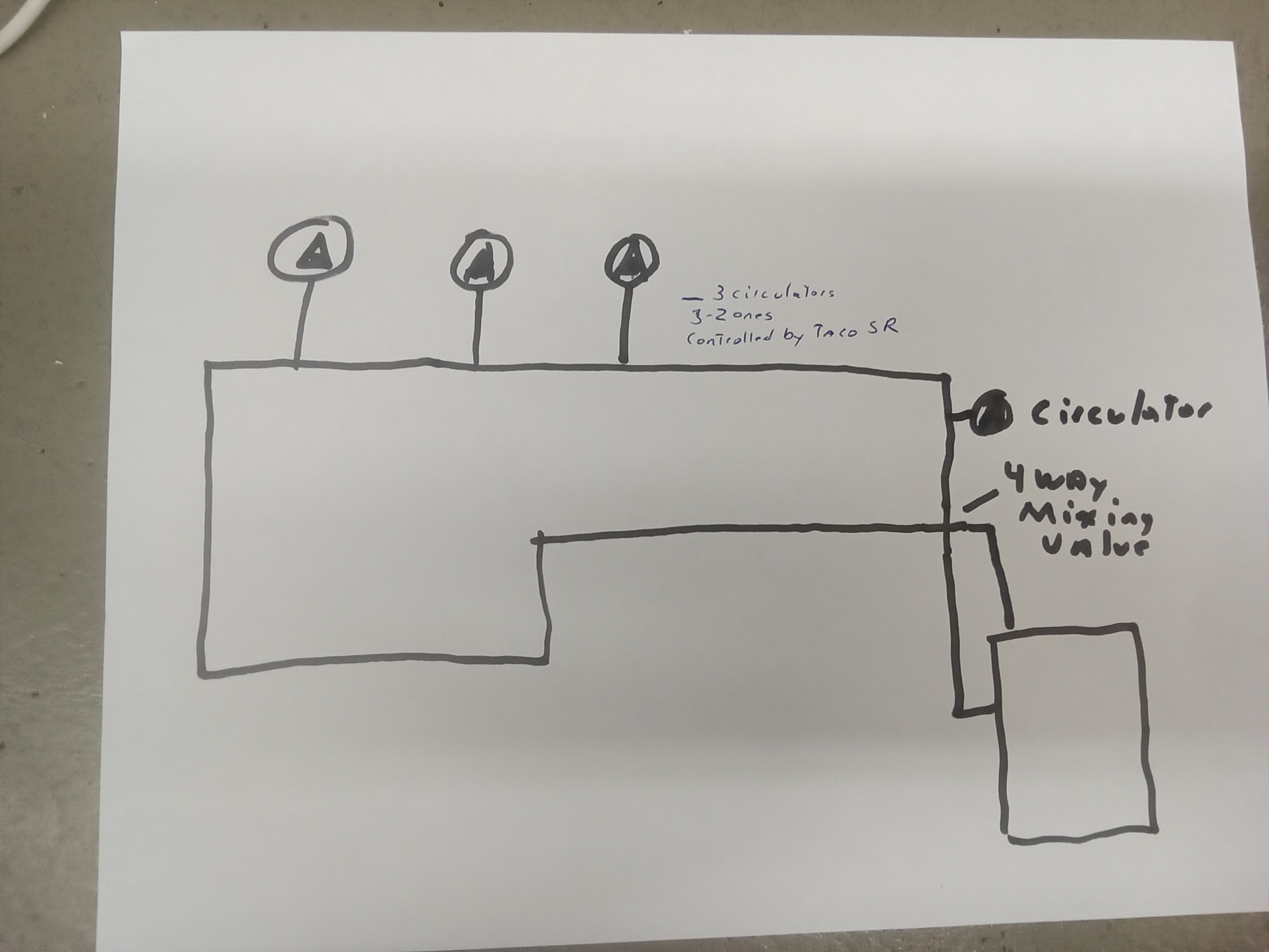
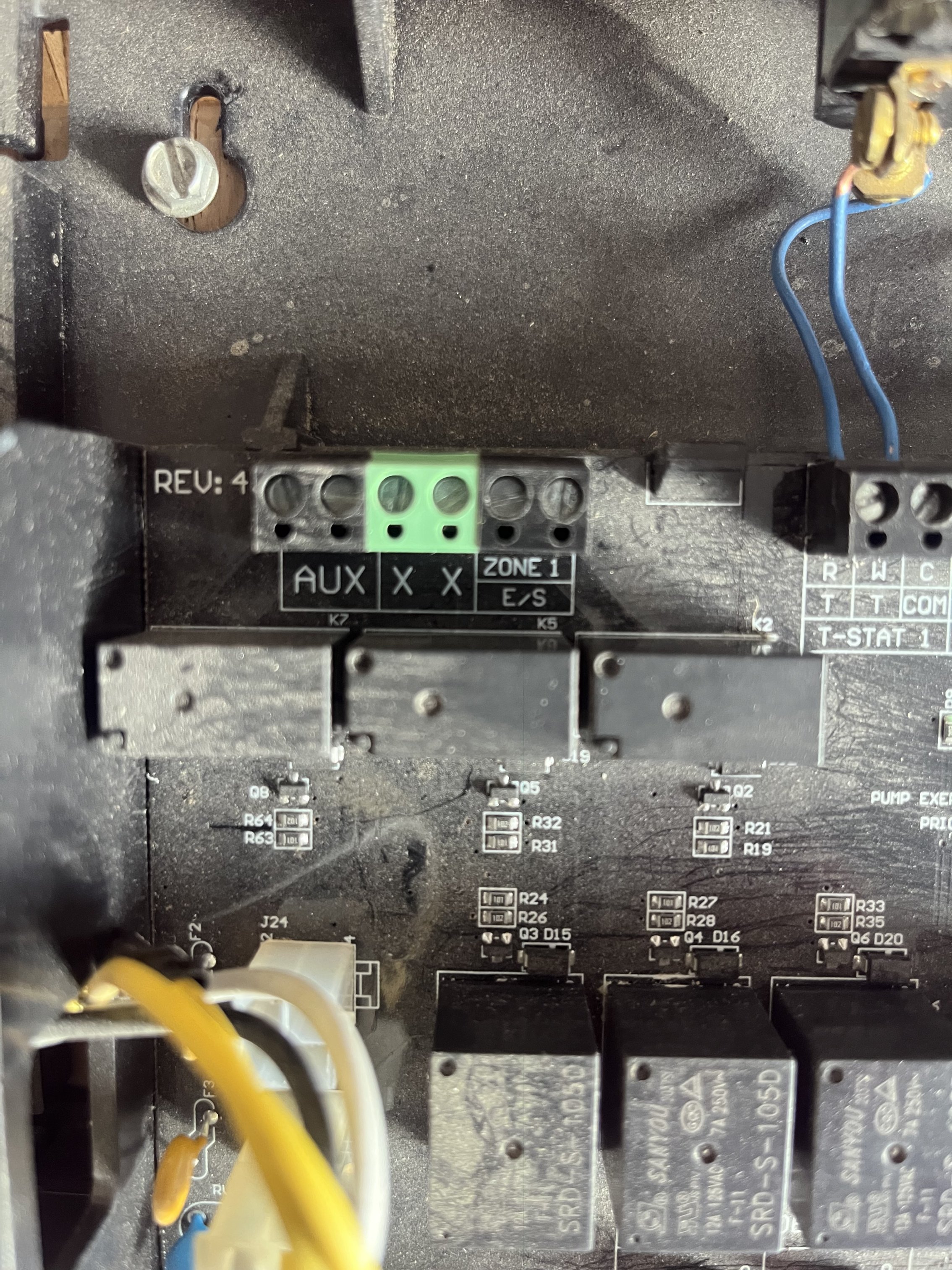
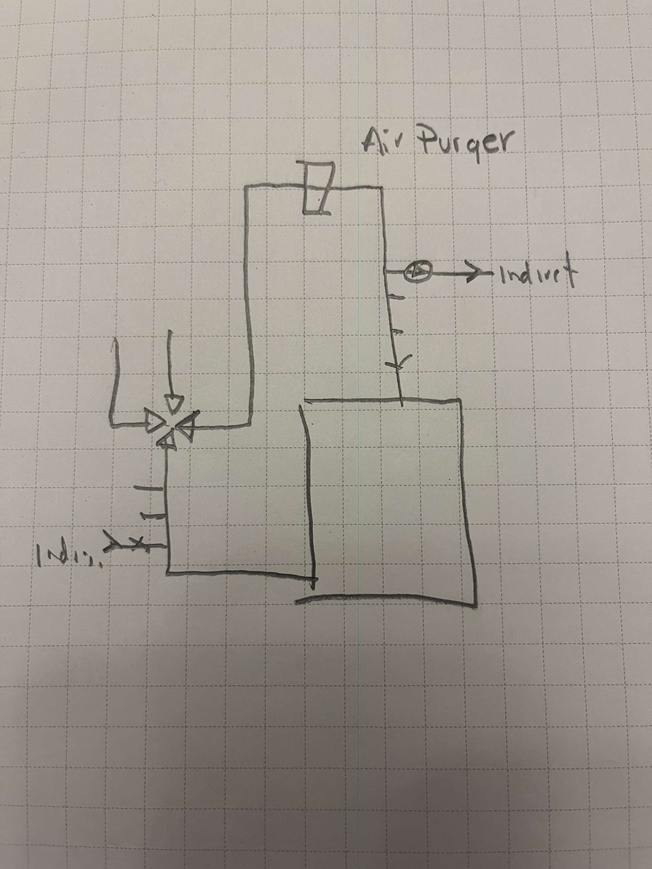
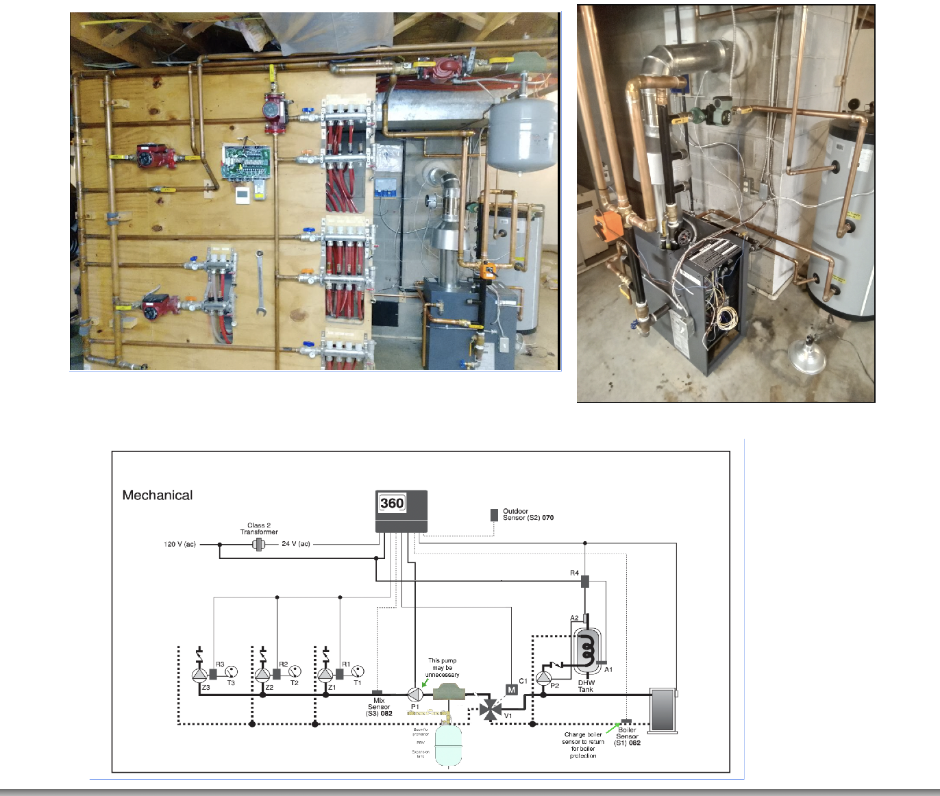
Bob,Here is a crude sketch! And a pic of the Tekmar .
Hope this is OK
Thanks
.
0 -
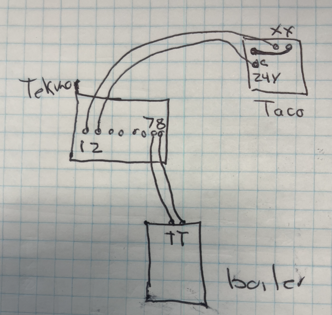
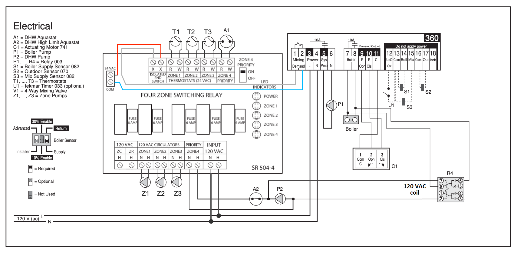
choices, the Taco box can run the system, or the tekmar.
My thought:
You need something (voltage) to turn on the tekmar 1&2 contact.
I would take 24V from the Taco, thru Taco XX over to the tekmar. This sends 24V to start the tekmar
Basically when any pump is turned on from the Taco SR, the XX connection sends 24V to the tekmar
tekmar 7&8 go to the boiler TT connection to call on the boiler when the pumps run and the tekmar wakes up
This is all low voltage 24V thermostat wiring.
@EdTheHeaterMan or @109A_5 may have other options, or a cleaner schematic
 Bob "hot rod" Rohr
trainer for Caleffi NA
Living the hydronic dream0 -
Again thanks for this help!
I do have a hvac friend who is assisting but I am trying to do as much legwork/brainwork as possible!
0 -
Forgot to ask. Terminal #5, Output Mixing System Pump??
0 -
Just know that some terminals are sensors, some are 24V, and some could be 120V, depending on your wiring choices. So you want to have someone with both 120V and low voltage wiring experience.
A meter is a good idea also to confirm voltages, relay closure etc.
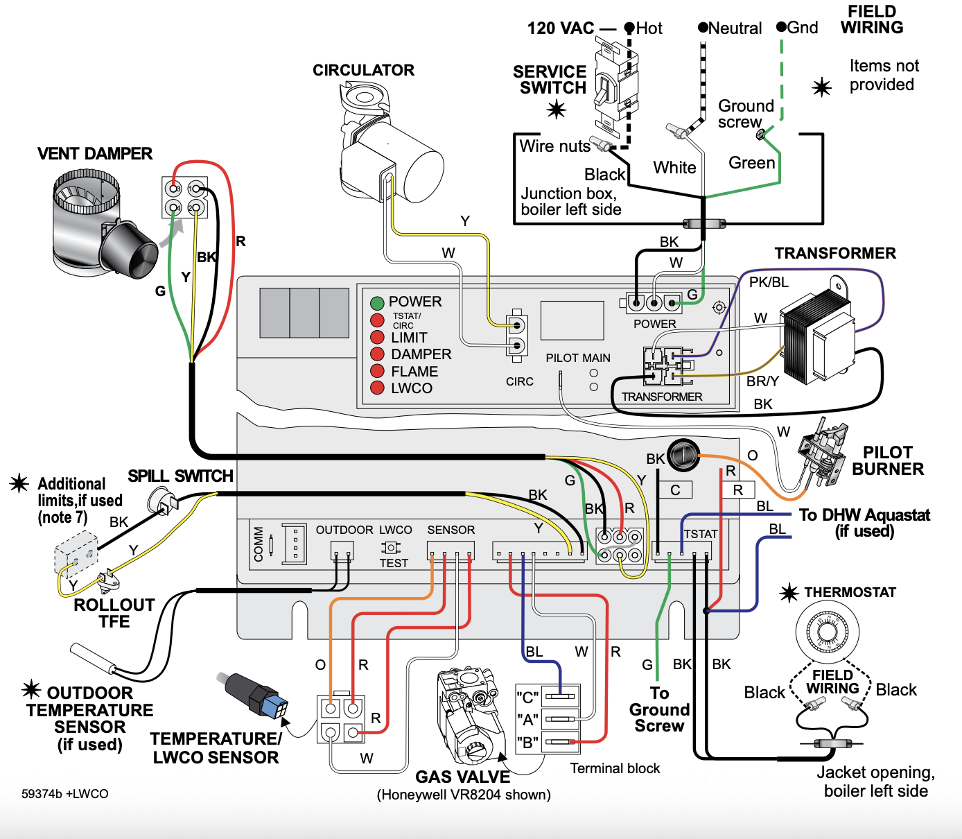
This should be what you boiler control module looks like. Where it shows *thermostat, that is where the Taco 7&8 connect.
Taco has a good wiring guide, for these more involved wiring logics, probably find it online
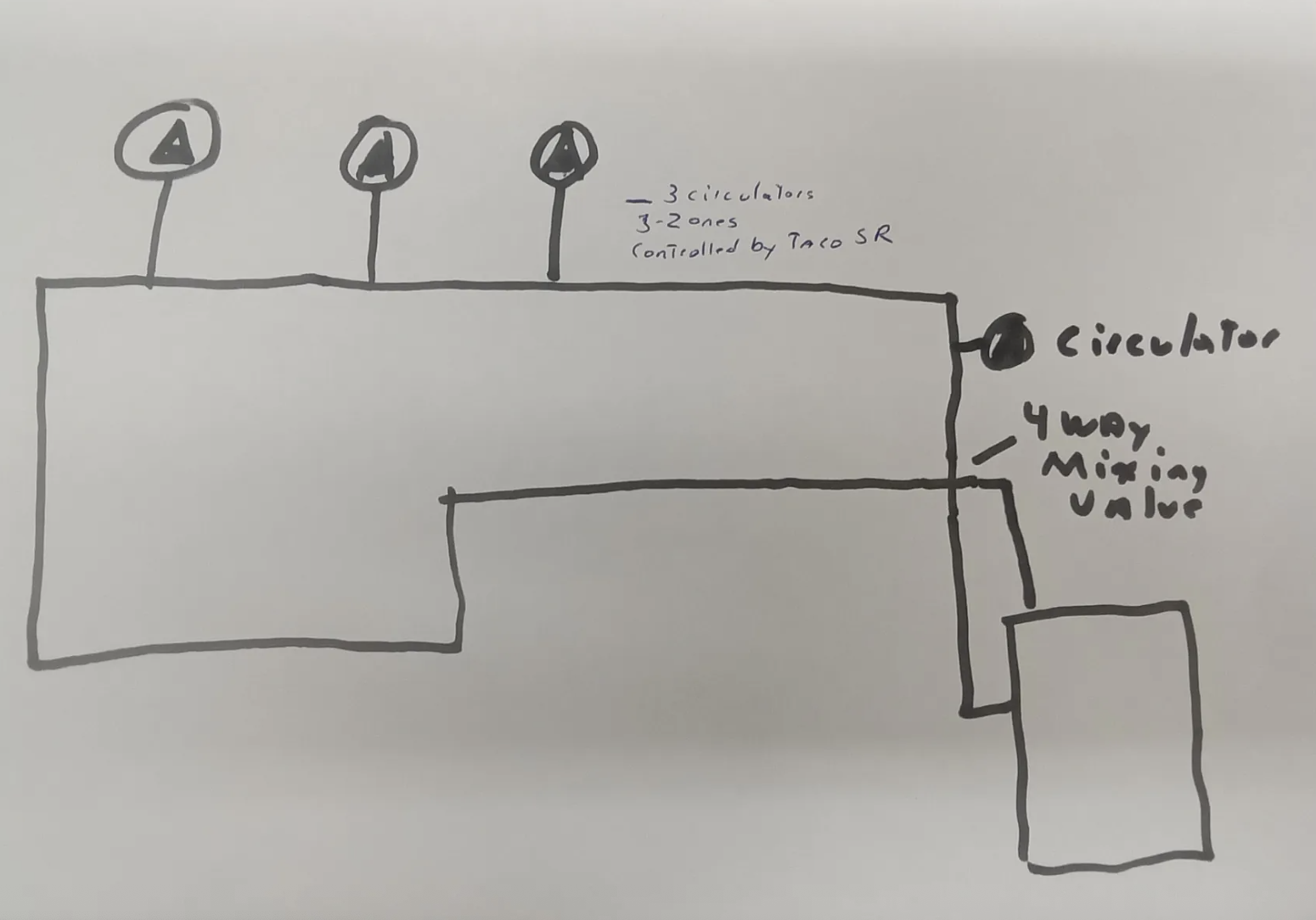
This drawing. I think all 3 zones have the ability to provide adequate flow for that small boiler, 3 gpm or so. So all you need are 3 zone pumps, which wire to the Taco box.
You don't need or want the circ you show above the boiler.
Bob "hot rod" Rohr
trainer for Caleffi NA
Living the hydronic dream0 -
As @hot_rod described the demand input just tells the Tekmar there is demand for heat, no demand no need to run the boiler, as shown below the Demand input could simply be Zone Valve End switches which are typically controlled by thermostats and zone valves for that zone.
 National - U.S. Gas Boiler 45+ Years Old
Steam 300 SQ. FT. - EDR 347
One Pipe System0 -
You can operate 2 pumps off of that #5 contact. According to the diagram L1 and Com (120 VAC) are connected to #3 and #4 respectively. When #1 and #2 get powered, a set of contacts connect #3 to #5 to operate the pump(s) that are connected to #5 and #6
If your pumps draw more start amps than the contacts are rated for, you may need an isolation relay.
In many cases you need two pumps when operating a 4 way valve. One is the boiler pump (or heat source pump) and the other is the system pump (or the pump that moves the lower mixed temperature thru the radiator system).
I hope this answers you query
Mr. Ed
Edward Young Retired
After you make that expensive repair and you still have the same problem, What will you check next?
0 -
Here is what I have come up with for you using a 3 zone Taco SR504.
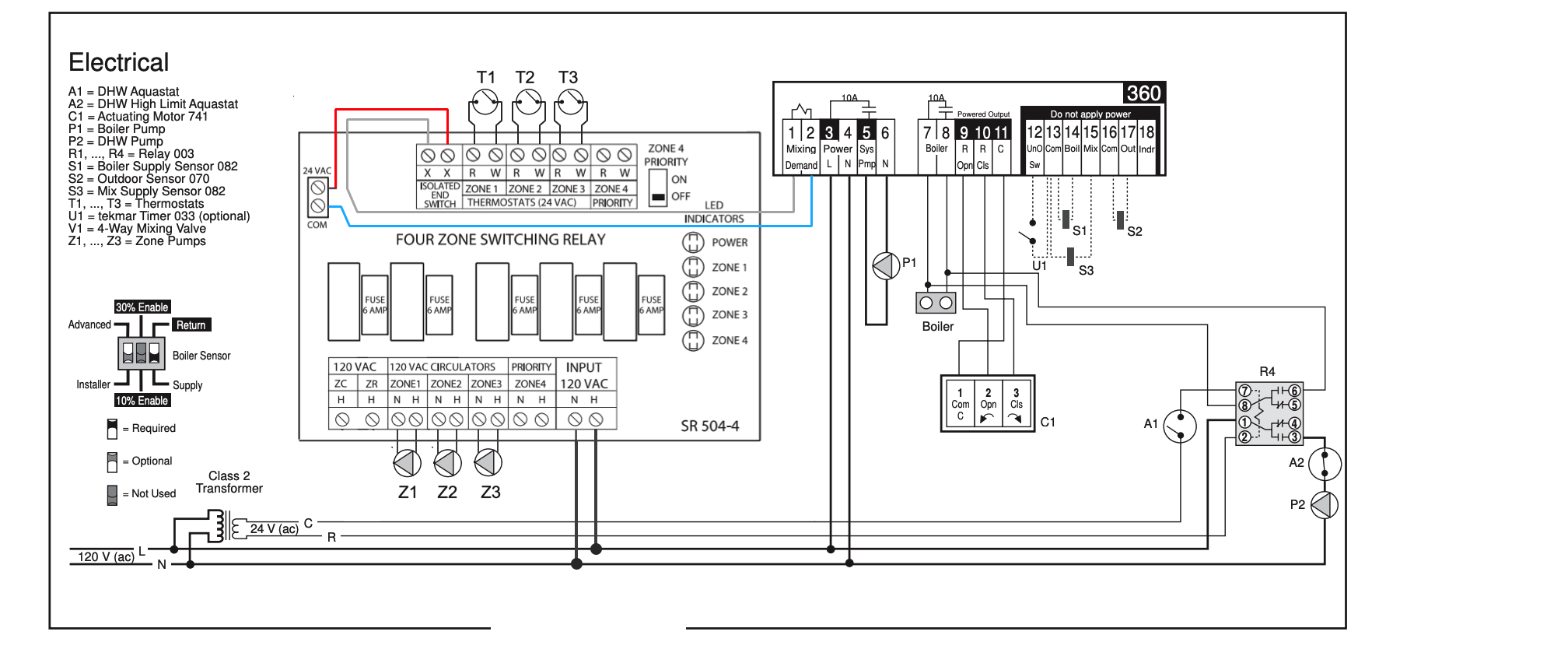
I think this will work for you.
There will be no DHW priority If you find that is needed, then R4 relay will need to be a 3PDT relay so there are extra contacts to break the LV power wire to terminal 1 on the Tekmar 360.
Let me know how this works for you.
Edward Young Retired
After you make that expensive repair and you still have the same problem, What will you check next?
0 -

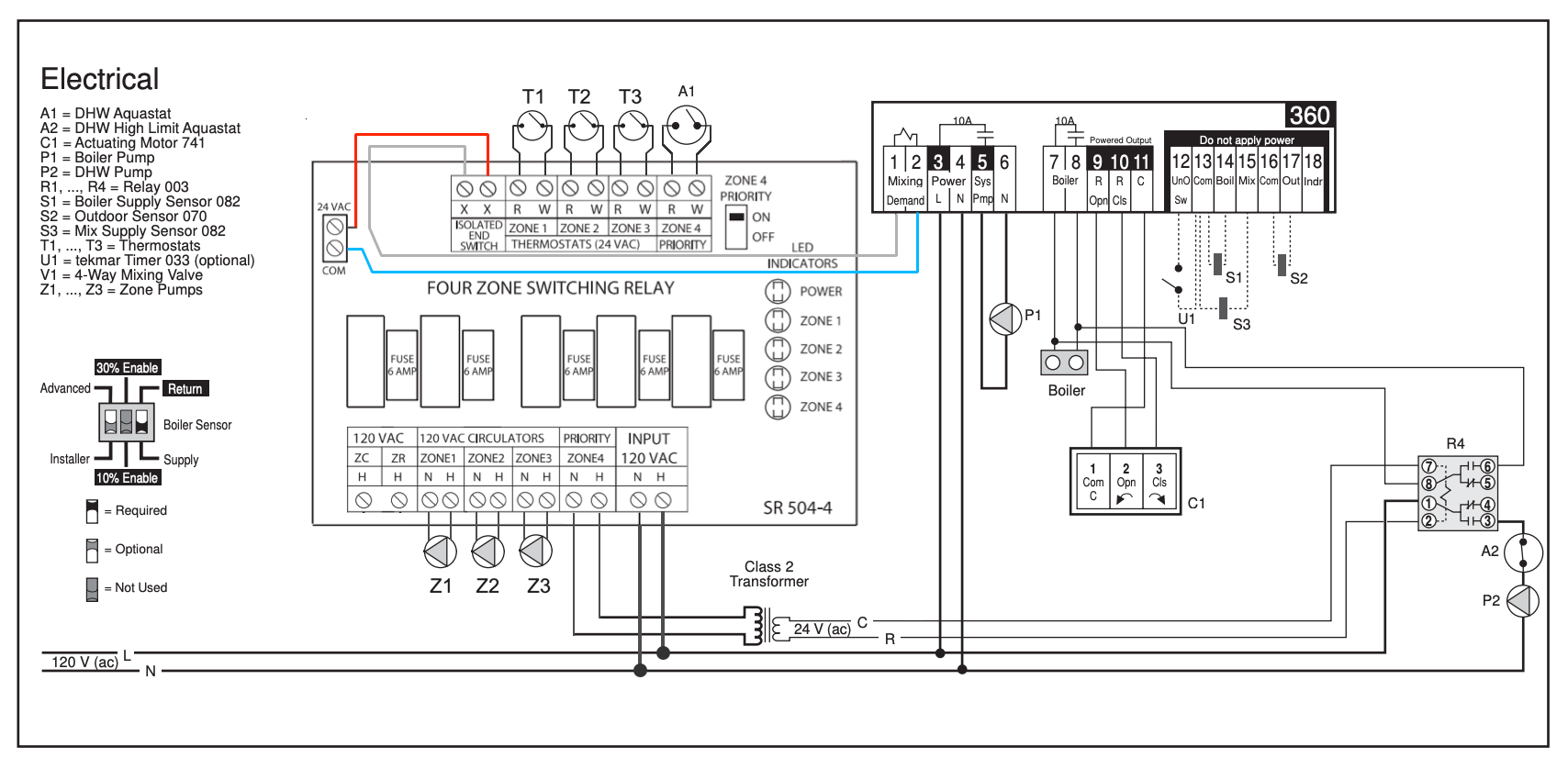
@EdTheHeaterMan why not add the DHW priority like this ? Also R4 could have a 120 VAC coil which would eliminate the extra transformer.
 National - U.S. Gas Boiler 45+ Years Old
Steam 300 SQ. FT. - EDR 347
One Pipe System0 -
7&8 on the tekmar is a dry contact, where does the boiler TT get closed on this drawing.
Either the tekmar or the Taco need to turn on a boiler call?
Bob "hot rod" Rohr
trainer for Caleffi NA
Living the hydronic dream0 -
@hot_rod asked: "7&8 on the tekmar is a dry contact, where does the boiler TT get closed on this drawing"
@EdTheHeaterMan answered: 7&8 on the tekmar is a dry contact, that's where the boiler TT get closed on this drawing
Edward Young Retired
After you make that expensive repair and you still have the same problem, What will you check next?
0 -
Or
 National - U.S. Gas Boiler 45+ Years Old
Steam 300 SQ. FT. - EDR 347
One Pipe System0 -
I looked at using the SR 504 priority zone for the DHW, however using that zone 4 will close the contacts for X X on the Taco SR 504 I believe. In this case, the P1 circulator will operate along with the ODR and Boiler Temperature to make the 4 way valve hunt for a place to settle even with no call for heat from any zone pumps. This may be problematic at times. By leaving the original Tekmar suggested R4 relay for the DHW zone, there should be no problem.
I believe that the high boiler temperature will act as the priority zone based on the way Tom piped the boiler and 4 way valve, without the need for shutting down the low temperature circulators electrically. If there is a call for heat from one or more of the low temperature zones and the boiler temperature to the 4 way valve is somehow reduced as a result of the DHW demand, that lower HOT inlet temperature to the 4 way valve won't matter because the 4 way valve will adjust the MIX temperature based on the MIX sensor.
I told Tom to try it out this way and if there is a problem maintaining enough DHW on the coldest days, then a 3PDT relay can replace R4 DPDT relay in the future. I believe I would then use your idea to connect the DHW aquastat to Zone 4 to make the 1 hour priority protection built into the Taco SR 504 operable. Thanks for that idea!
Edward Young Retired
After you make that expensive repair and you still have the same problem, What will you check next?
0 -
BIG EDIT
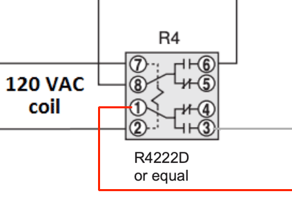
@Cyclist77 this is the relay I was thinking of for R4 on the diagram
WR 90-340.WR 90-341 You can pay more for the Honeywell that is identicalHoneywell/Resideo R8222D. Honeywell Resideo R4222D and use the last diagram I posted as a result of @109A_5 ideas. I'm so glad I did this, great minds coming together will always have a better idea than just one So So mind like @109A_5 has. LOL. Actually he has some really good ideas!Edward Young Retired
After you make that expensive repair and you still have the same problem, What will you check next?
0 -
Or better yet
 National - U.S. Gas Boiler 45+ Years Old
Steam 300 SQ. FT. - EDR 347
One Pipe System1 -
That second is great @109A_5. that leaves the additional contacts for breaking the power to 1 and 2 to the Tekmar like this
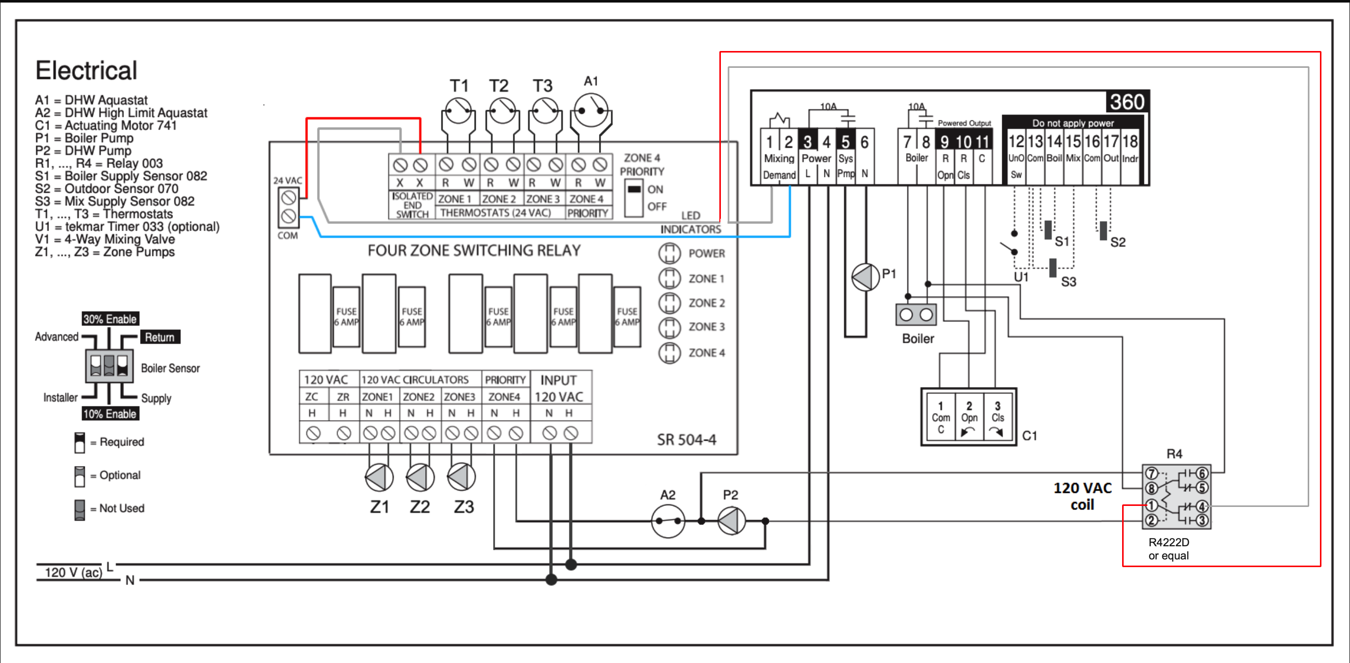
Now this is truly priority without operating the 4 way valve and the P1 pump
NICE!
Edward Young Retired
After you make that expensive repair and you still have the same problem, What will you check next?
0 -
you could connect a RIB onto the tekmar box
Many of the RIBs have multi voltage coils giving you options.
If the OP doesn’t have the relay box yet, the Caleffis give you 3 dry contacts, one dedicated to DHW priority
 Bob "hot rod" Rohr
trainer for Caleffi NA
Living the hydronic dream1 -
@EdTheHeaterMan to minimize confusion if these ideas are used. If the DHW priority is not active, so the Tekmar Demand is active the R4 terminals 1 and 4 need to be used (NC, Normally Closed).
 National - U.S. Gas Boiler 45+ Years Old
Steam 300 SQ. FT. - EDR 347
One Pipe System0 -
To use an old saying "You guy's are the bomb"!!!
I have been taking Screenshots and send them to the fellow that is helping me.
0 -
if you like all the switching on the hot side of the 24 VAC power supply do it like this.
 National - U.S. Gas Boiler 45+ Years Old
Steam 300 SQ. FT. - EDR 347
One Pipe System0 -
A couple questions, do you have an indirect tank in the piping? Show how you piped it.
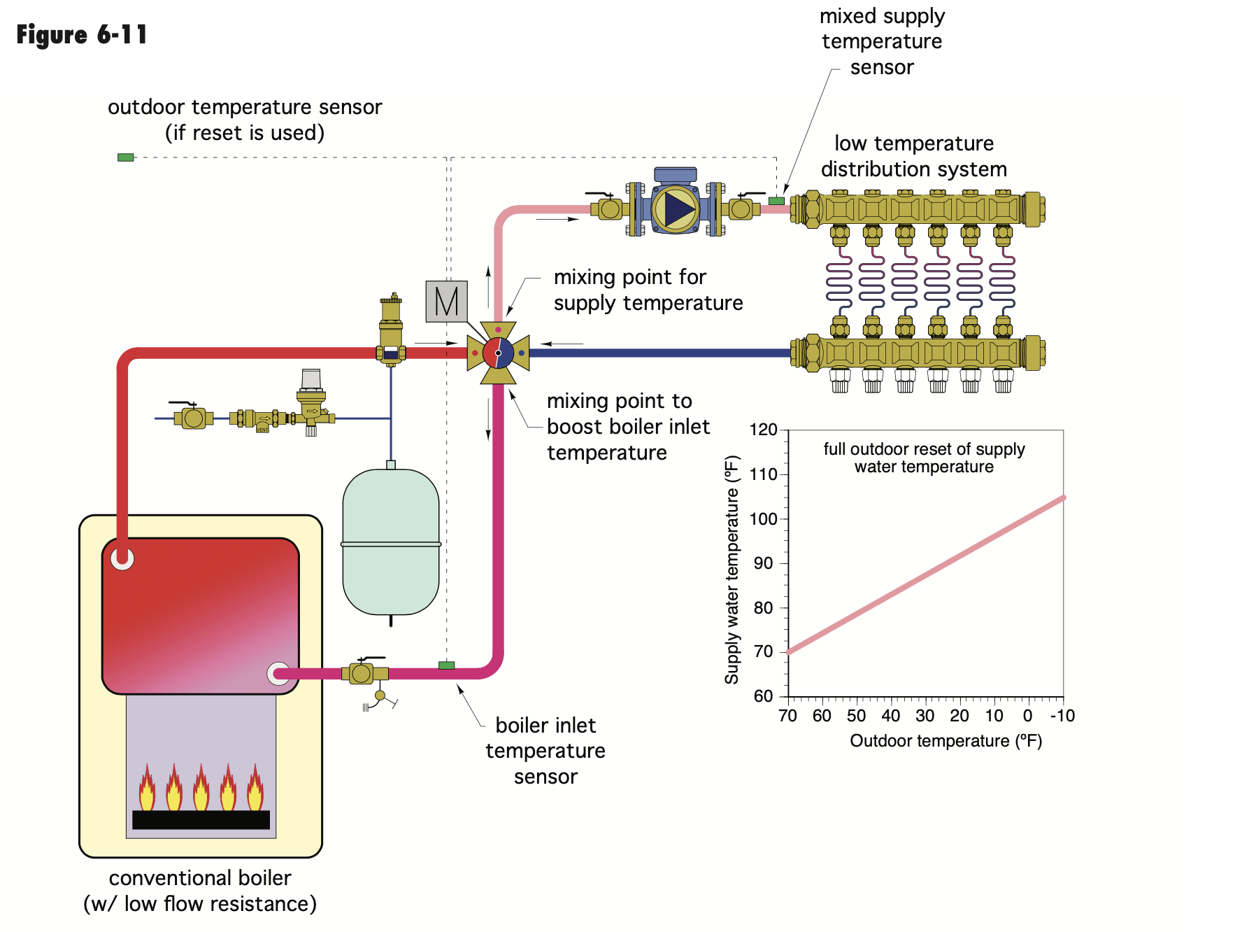
Here are two way to properly pipe a 4 way. With a low pressure drop boiler you should not need a boiler loop pump.
If you insist, it needs to pipe like fig 6-12
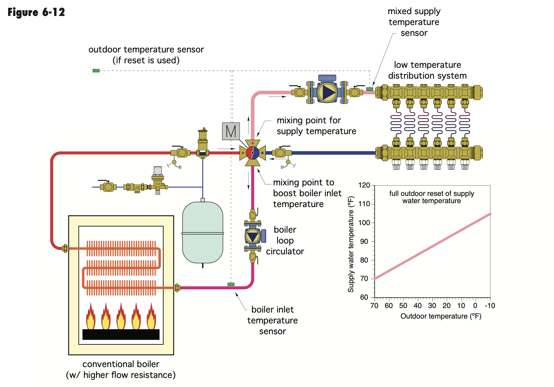
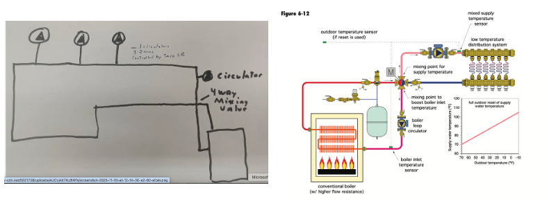
Is this sketch how it is piped? If so you do not have a boiler loop or pump in it. You look to have a random pump in series with zone pumps. Nothing on the boiler loop
Here they are side by side
 Bob "hot rod" Rohr
trainer for Caleffi NA
Living the hydronic dream0 -
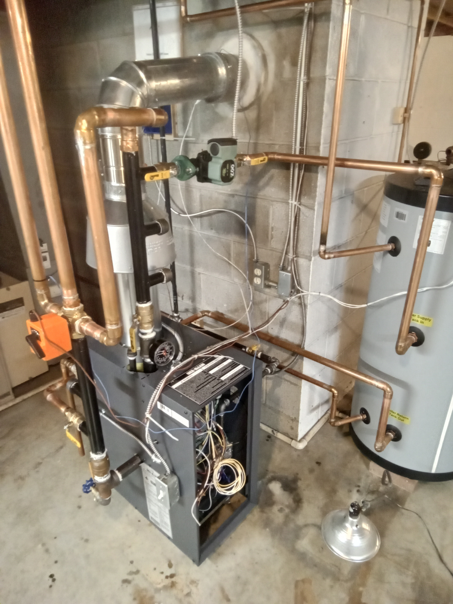
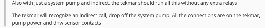
Here is a pic showing the Indirect DHW piping.
 0
0 -
@Cyclist77can you take and post a photo of the front of the boiler from floor to ceiling so I can see how the supply pipe on the boiler is attached to the 4 way valve? The boiler in the center and the DHW on the right and the edge of the plywood with three zone circs on the leftNevermind
By the time I hit send… it was already there
Edward Young Retired
After you make that expensive repair and you still have the same problem, What will you check next?
0 -
the black header off the top, what are the extra connections for?
Bob "hot rod" Rohr
trainer for Caleffi NA
Living the hydronic dream0 -
I wanted to keep my options open! Maybe a 180f loop to our mudroom and a radiator.
0 -
The Hot Water zone piping looks correct w/P2
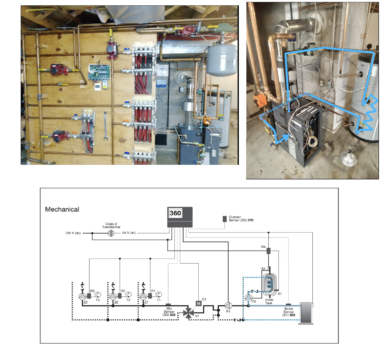
Follow the blue pipes from boiler supply to the P2 to the DHW to the boiler return.
Edward Young Retired
After you make that expensive repair and you still have the same problem, What will you check next?
0 -
show the piping from the 4 way on
Boiler piping looks good, is there an air purger up top?
 Bob "hot rod" Rohr
trainer for Caleffi NA
Living the hydronic dream0 -
This supply to return primary loop is not as Tekmar illustration suggests. However if it is short enough it may work. there is no boiler pump P1 on the boiler loop and you dont want one if you conect the boiler direct to the 4 way valve. This will not work on a ModCon because there will not be enough water flow thru the boiler in some circumstances.
I would recommend the P1 pump be on the boiler primary loop and use the closely spaced tees within inches of the 4 way valve. You decide if the piping you already have is adequate.
See how the red pipes have no circulator pump from the boiler supply to the 4 way valve and from the 4 way valve to the boiler return? You are depending on the zone pumps to pull the heated water from the boiler thru the 4 way valve. If that pipe run is not too long it might work.
Edward Young Retired
After you make that expensive repair and you still have the same problem, What will you check next?
0 -
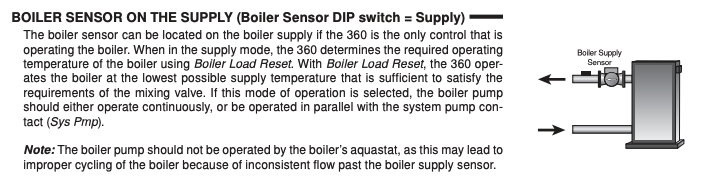
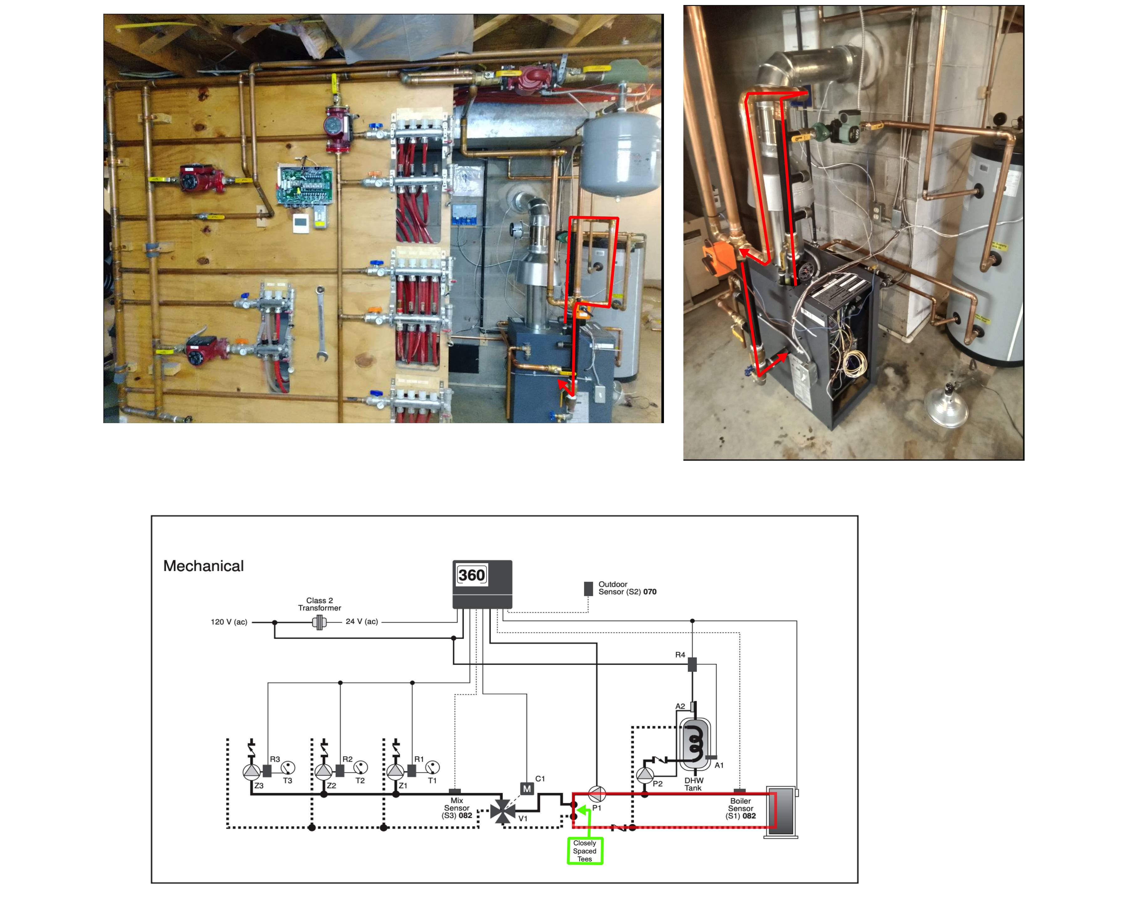
This piping design is as close as I can come to what you have built. There is a possibility that this will work. since this is cast iron, there is no minimum flow needed thru the heat exchanger of the boiler like a ModCon. Thge high limit will keep the boiler from overheating and placing the Boiler Sensor on the return (and setting the dip switch accordingly) will reduce the chance of flue gas condensation (aka: boiler protection) will allow this to operate even if there is minimum flow thru the boiler
I would like to hear @hot_rod' opinion on this design. I believe he mentioned something in a previous post about the P1 circulator being added to the zone circulator pump head. I'm not sure if that is good or bad. He would know better than me.
Edward Young Retired
After you make that expensive repair and you still have the same problem, What will you check next?
0 -
I thought we went through the piping in an earlier post?
If you have a low pressure drop boiler, you do, and the 4 way is piped close to the boiler, it is, the 3 zone pumps should make this work
Eds first drawing marked in red is a primary secondary piping. Typically used with a higher pressure drop boiler
Id still like to see the rest of the piping that you have on the copper out of the mix
Also with just a system pump and indirect, the tekmar should run all this without any extra relaysThe tekmar will recognize an indirect call, drop off the system pump. All the connections are on the tekmar, pump power and dhw sensor contacts
The 4 way looks large, did you go with the 1-1/4”? It may hunt a bit if it is oversized for the actual flow. I think we covered that early on also
Bob "hot rod" Rohr
trainer for Caleffi NA
Living the hydronic dream0 -
Not seeing anything in the Tekmar documentation that supports either of these statements. Not with the Tekmar 360, they show a relay (R1 or R4) added for DHW in each example. And no input (or output) to the Tekmar 360 for DHW purposes. Maybe you are thinking of a different Tekmar product.

 National - U.S. Gas Boiler 45+ Years Old
Steam 300 SQ. FT. - EDR 347
One Pipe System0


Categories
- All Categories
- 87.6K THE MAIN WALL
- 3.3K A-C, Heat Pumps & Refrigeration
- 59 Biomass
- 430 Carbon Monoxide Awareness
- 124 Chimneys & Flues
- 2.2K Domestic Hot Water
- 5.9K Gas Heating
- 120 Geothermal
- 168 Indoor-Air Quality
- 3.8K Oil Heating
- 78 Pipe Deterioration
- 1K Plumbing
- 6.6K Radiant Heating
- 394 Solar
- 16K Strictly Steam
- 3.5K Thermostats and Controls
- 56 Water Quality
- 51 Industry Classes
- 50 Job Opportunities
- 18 Recall Announcements