Help with piping configuration and head loss

Hi everyone!
I'm trying to learn more about the piping configuration of my 4-family apartment building.
I'm learning so much here by the generous help from @EdTheHeaterMan , @hot_rod, @leonz, @EBEBRATT-Ed, @WMno57, @mattmia2 and many others. Thank you!
-This is a 1937 brick, 2-story apartment building in Cincinnati.
-2- pipe, singe zone hydronic heating with recessed, fin-tube, baseboards.
-CG8 (202,000 rated output boiler - which replaced a oil boiler many years back (1994).)
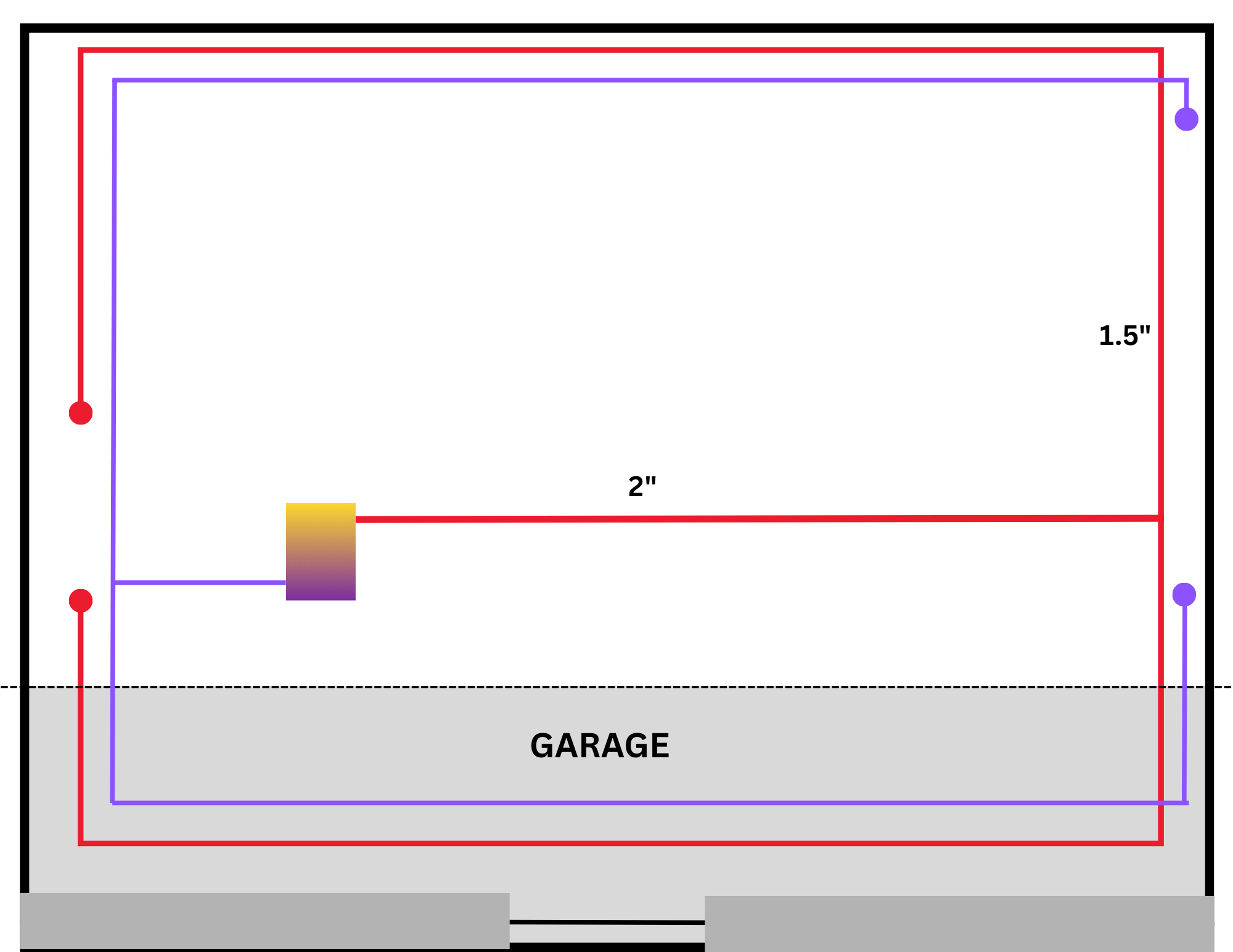
I've included a sketch of the piping configuration. I ommited the reducing tee's from the 1.5" supply and return to each 1st floor convectors via 1/2", as well as the tee's for the 3/4" risers to the seconds floor.
The piping from the boiler in the basement is uninsulated by design.
There is also a below grade garage which is heated by the same uninsulated piping.
I've discovered "dead ends", 2 per supply and return. Is this indicative of a specific type of piping?
Lastly, when calculating the initial head loss of the piping in this setup, should I assume I would measure the length of BOTH the supply and return 1.5" piping, as well as calculating the loss of the fittings?
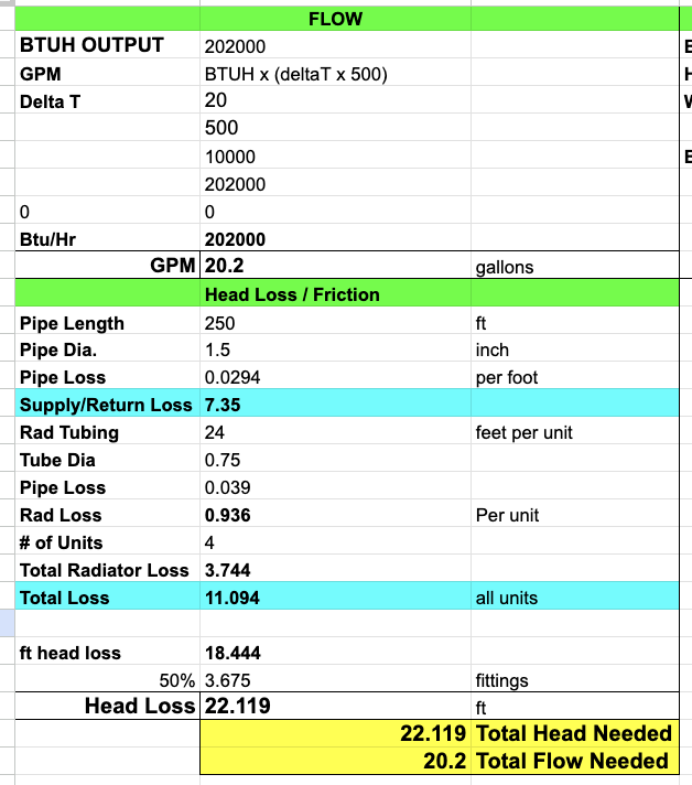
Based on what I THINK I've learned, the flow rate is roughly 20GPM for 200,000 output boiler at 20 delta T?
Thanks for any help!
Nicholas
Comments
-
Interesting diagram. I might add something to this diagram to illustrate that you probably have what is known as a reverse return system.
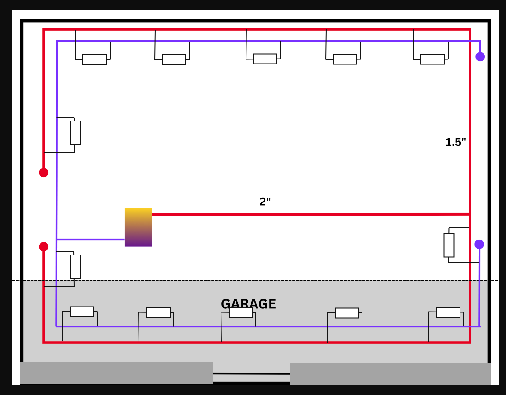
When a system is piped this way every radiator has about the same amount of piping from the boiler to the radiator and back to the boiler. The first radiator on the supply is the last one on the return and the last one on the supply is the first one on the return, and all the middle radiators have an equal amount of supply and return total piping. This makes the friction loss of the water moving thru each radiator about the same, and the means that all the radiators should heat and cool at the same rate.
Older gravity systems were piped where each radiator had a direct return meaning some radiators had long supply and return runs while the radiators closer to the boiler might have very short runs. On gravity circulated systems that didn't matter so much, however, when someone adds a circulator to such a system, the short runs may get over heated while the longer runs may not get enough heat.
See if your radiators are connected as I have illustrated and if so you have a well designed (more expensive to install) system.
@AlwaysLearning2024 said: "Lastly, when calculating the initial head loss of the piping in this setup, should I assume I would measure the length of BOTH the supply and return 1.5" piping, as well as calculating the loss of the fittings?"
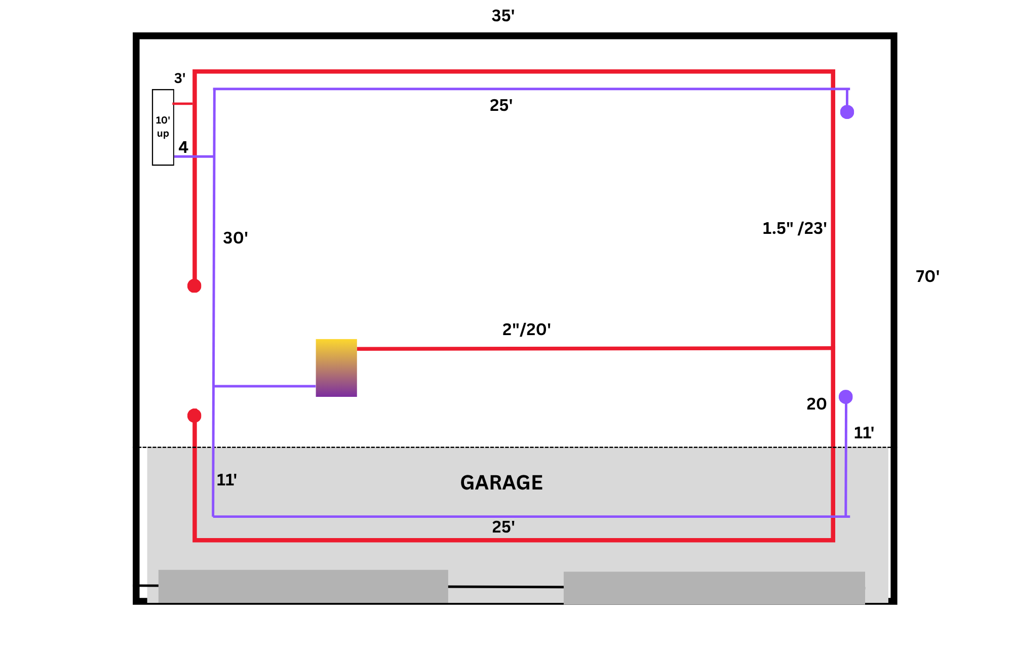
When using the longest run method for calculating Pump Head, you need to measure the longest run for the radiator that is farthest from the boiler. That means the longest pipe run. and that could actually be the radiator closest to the boiler when you have reverse return system. when looking for the longest pipe run I try to make it simple. It is usually the radiator farthest from the boiler so I measure the total length of the building from the boiler room to that far radiator. that usually means the length and the width of the building as illustrated here.
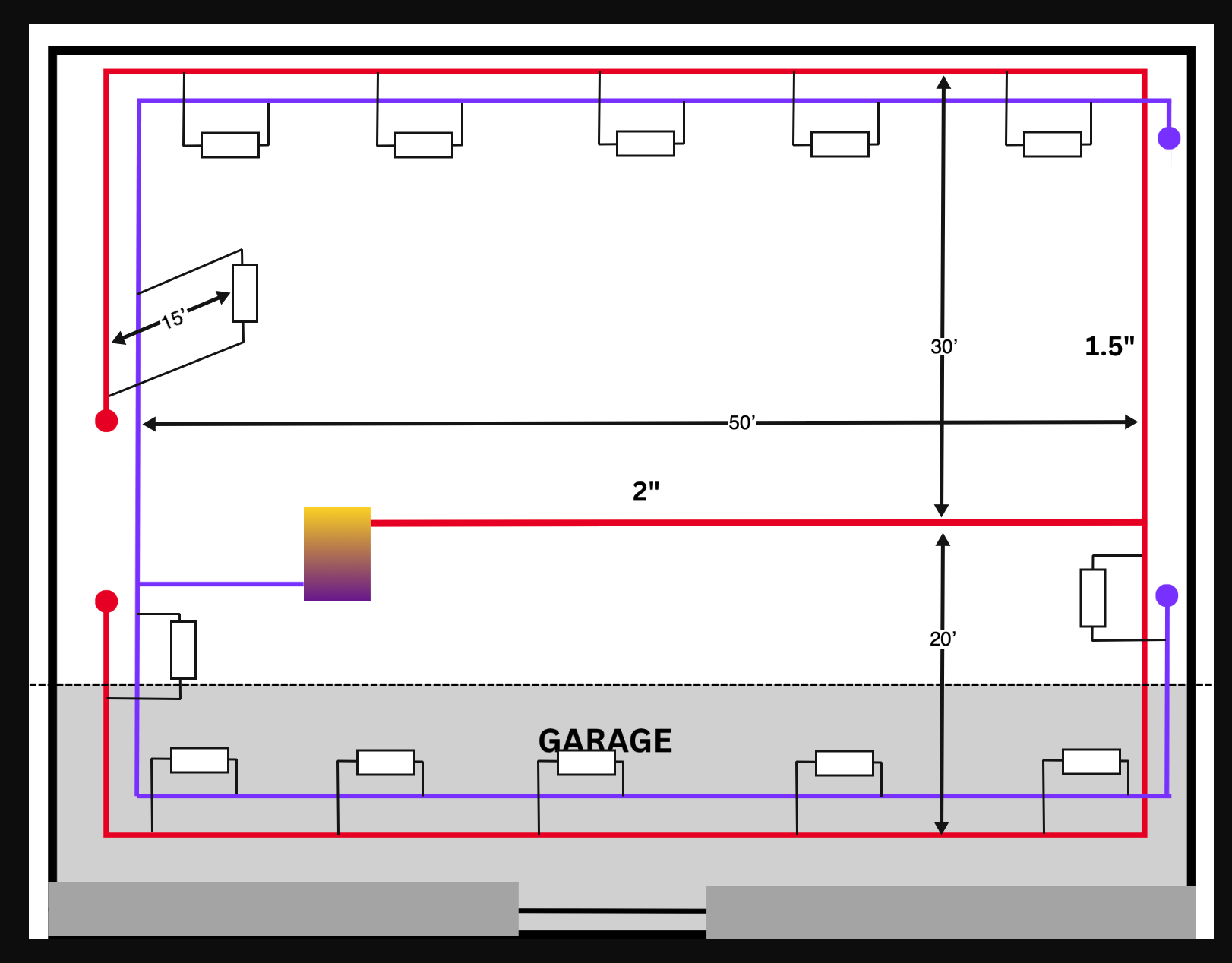
According the the dimentions that I have added to your diagram, the longest run would be the upper zone since it has 30 feet of pipe from the 2" main to the upper wall, the lower zone has only 20 feet. and the farthest radiator is on the second floor and that is about 15 feet above the boiler room. I would just add 50' + 30' + 15 ' to get 95 feet. That will account for the supply side of the piping. I would add another 95 feet to account for the return side of the piping. So in answer to your query measure both the supply and return the answer is YES, because the water must flow thru all of those pipes to make a complete cycle. You must also measure the common piping so the 2" is included.
When using the rule of thumb for longest run method, you need to add something for the Equivalent Length of all the fittings and some use 50% or multiply times 1.5 to get 285 total Equivalent Length. Now use that number to get your pump head required by multiplying by .04 because you need to overcome about 4 feet of friction for every 100 feet of pipe in order to keep the noise of flowing water to a minimum. In this example the pump heat would be about 11 feet of head. So, this pump will need to move about 20 GPM at 11 Ft Head. This is actually over kill by as much as 20% but well within the parameters of the pump selected by this method. Now you will need to use your actual measurements to get your pump head.
Edward Young Retired
After you make that expensive repair and you still have the same problem, What will you check next?
1 -
Yes @EdTheHeaterMan ! This is very helpful and accurate. Reverse return it is! good to know this was designed well! Thank you!
Obviously some of the radiators are on the second floor with 3/4" piping from the 1.5" piping instead of 1/2 inch piping to the first floor.
Any best practices with calculating the head loss? At this point, I've figured the following:
Am I off track here with needed head from the circulator or flow rate?
 0
0 -
I believe you are a little bit high. I have some questions. they are on the line that I have a question about below:
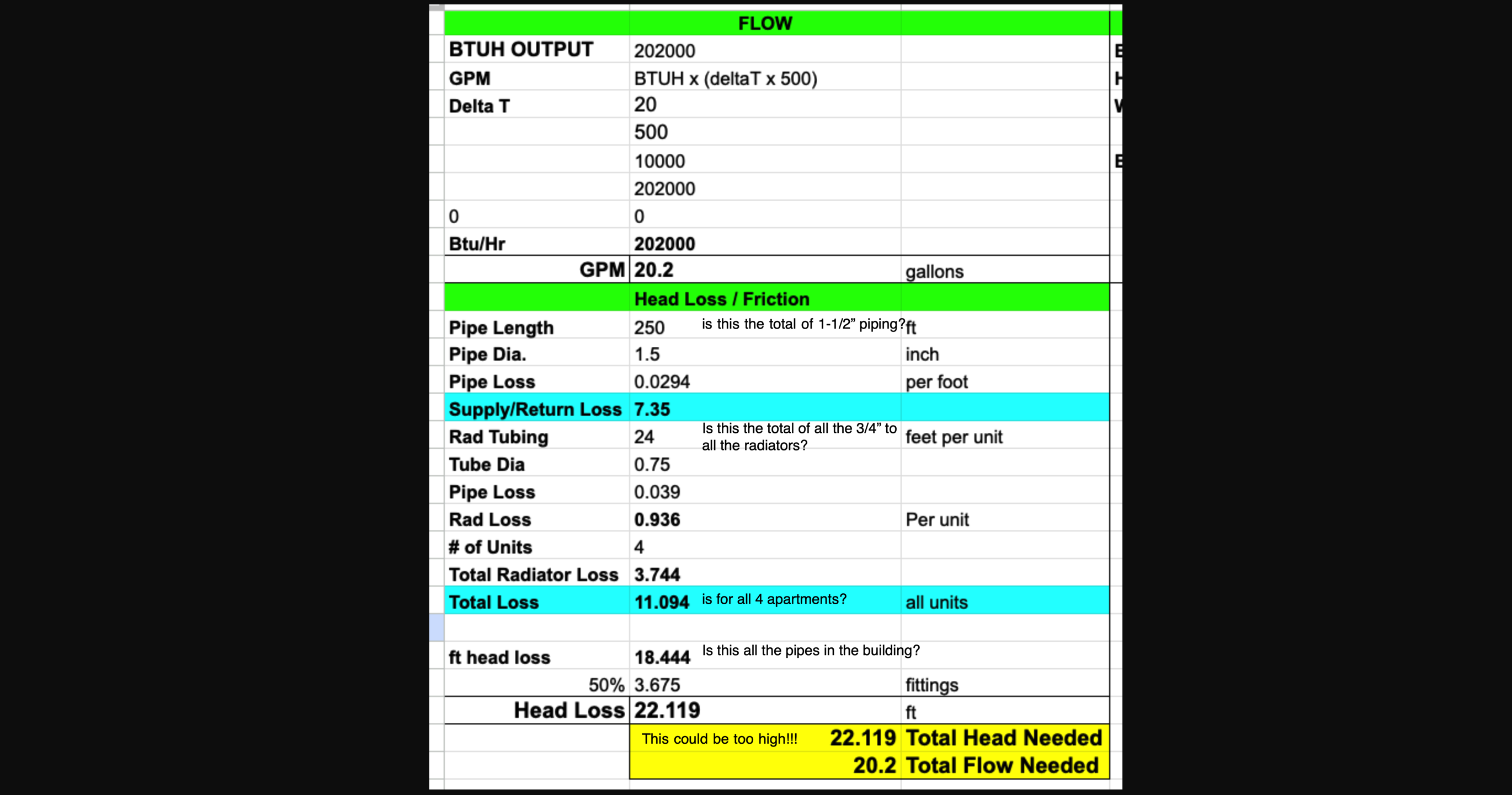
I also do not see a number for the 2" pipe in your diagram. Is that part of the 1-1/2" length total?
This is why I like the simple rule of thumb for the longest run method. Can you give me the length and width of the total building. outside dimension x outside dimension? Also, if the the main 2" pipe is in the middle of the building or off to one side or the other?
I believe you are counting ALL the pipes to come up with your pump head/friction loss number. The concept of the longest run is to measure only one trip from the boiler to one of the radiators (not all the radiators) and back to the boiler. If the pump can move the water to the farthest (hardest to get to) radiator, then the round trip to all the other radiators (shorter runs) will be no problem for that pump
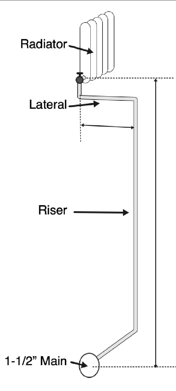
Can you also tell me the approximate length of one of the longest 3/4" risers from the 1-1/2 main to the radiator on the second floor. Actually it would be the hight from the 1-1/2" main to the bottom of the radiator. Include any lateral (horizontal) piping after it gets to the second floor between the first floor ceiling and the second floor subfloor before it turns up thru the floor to connect to the radiator?
I have studied how to calculate the Total Equivalent Length of pipe using a EL chart that lists every valve and fitting's EL by the pipe size. This needs to be done on commercial jobs because being up to 20% oversized can mean thousands of dollars in selection a larger pump than needed. When you are talking about a 200,000 BTU boiler output, that is not going to be that big of a deal.
What is a big deal is measuring all of the risers to 20+ radiators and both 1-1/2" main pipe and coming up with 22 ft head when you may only need 12 or 16 ft head can make for a noisy system, pump cavitation and all sorts of other issues.
What are the building's dimensions?
Edward Young Retired
After you make that expensive repair and you still have the same problem, What will you check next?
0 -
With using just your numbers I only come out with about 15' of head.
Siggy did a webinar about using a rig to figure out actual head in a system, especially if you don’t have access calculate all the pipe fittings.
0 -
Thanks! @EdTheHeaterMan and @HydronicMike!
Measurements in the pic.
Basics:
Outside dimensions are roughly 70' x 35'
Furthest supply pipe to radiator is:
- 20' of 2",
- 51' of 1.5"
- 4' 3/4" lateral to 2nd floor
- 10" 3/4" riser.
The boiler is roughly in the middle of the building.
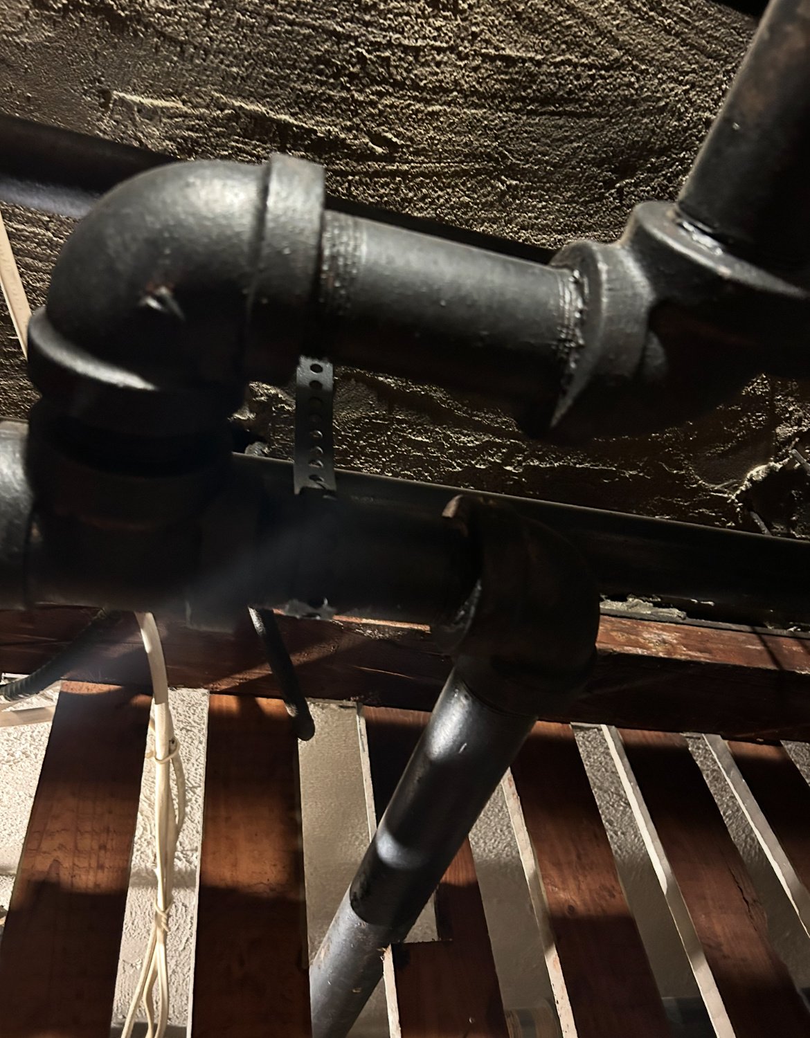
There is a 2" 20' pipe from boiler to the first supply tee (photo attached). All other "basement" piping is 1.5".
 0
0 -
Easy measure method. building is 70 x 35. with one side about 40 ft from the center 2" main and the other side about 30 ft from the 2" main. The furthest radiator is on the second floor and next to the outside wall. This easy calculation method will actually be a little longer than the actual measurement.
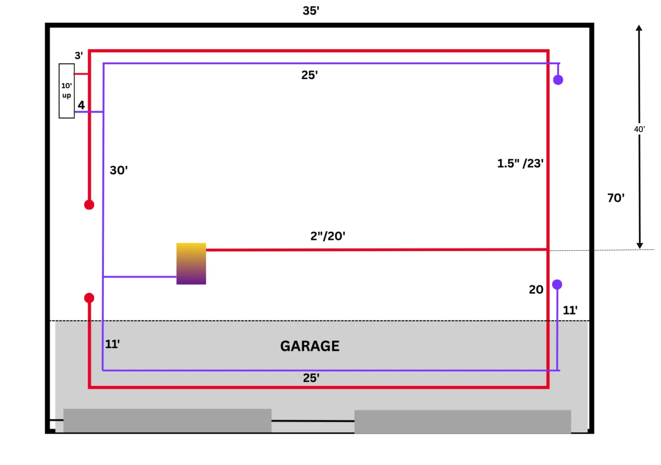
40 + 35 + 10 = 85 strait pipe one way.
85 x 2 = 170' the complete round trip
170 x 1.5 = 255' for fittings (TEL)
255 x 0.04 = 10.2' Head
You need a pump that can move 20 GPM when there is 10.2 ft Head/Friction loss
If you measured every fitting, every tee, every valve, every elbow, every length of pipe down the the inch and added them all up you might find that you can get away with only 9 Ft head and that would get you to select a Taco 0012. See how this is not rocket surgery? You just got to get close without going double the size. That could put into a different category of commercial pumps completely.
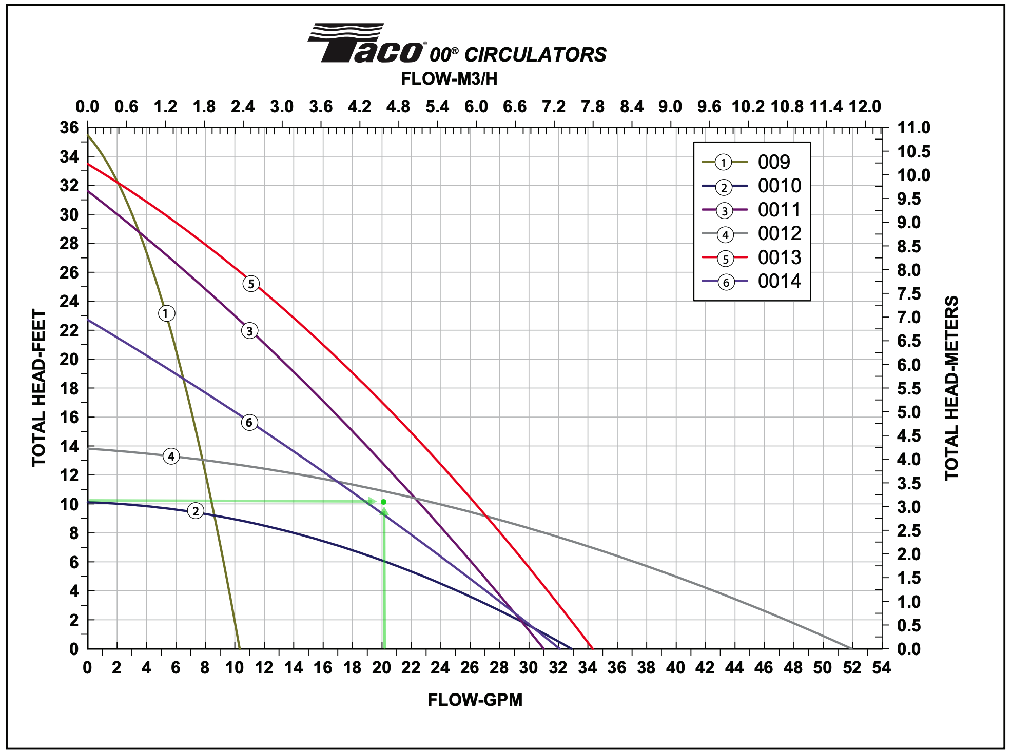
The Green dot on the Taco pump curve indicates that the best pump for your situation would be the Taco 0012 F4 since the spot 10.2 ft Head @ 20 GPM on the grid falls below the 0012 curve.
I had a feeling that you may have overestimated your actual needs. You might want to read this book. Zoning Made Easy. It will tell you a lot about how your boiler system works. The Pump Head calculation is on page 8 column 2.
Edward Young Retired
After you make that expensive repair and you still have the same problem, What will you check next?
1 -
Thank you, @EdTheHeaterMan ! This makes sense now! I've just downloaded the "Zoning Made Easy", also.
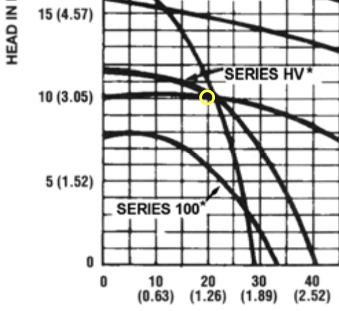
I have access to an older B&G HV Pump with solid motor mounts and a Spiralink coupler. The pump curve looks like a good fit, also.
Would this be a workable solution as an alternative to the Taco 0012?
 1
1 -
B&G HV is a match!
Edward Young Retired
After you make that expensive repair and you still have the same problem, What will you check next?
0

Categories
- All Categories
- 87.6K THE MAIN WALL
- 3.3K A-C, Heat Pumps & Refrigeration
- 59 Biomass
- 429 Carbon Monoxide Awareness
- 124 Chimneys & Flues
- 2.2K Domestic Hot Water
- 5.9K Gas Heating
- 119 Geothermal
- 168 Indoor-Air Quality
- 3.8K Oil Heating
- 78 Pipe Deterioration
- 1K Plumbing
- 6.6K Radiant Heating
- 394 Solar
- 15.9K Strictly Steam
- 3.5K Thermostats and Controls
- 56 Water Quality
- 50 Industry Classes
- 50 Job Opportunities
- 18 Recall Announcements