Adding a radiant manifold to existing single zone loop

ok just trying to think this through ahead of time. I have read books and articles on this but theory and practice are not the same
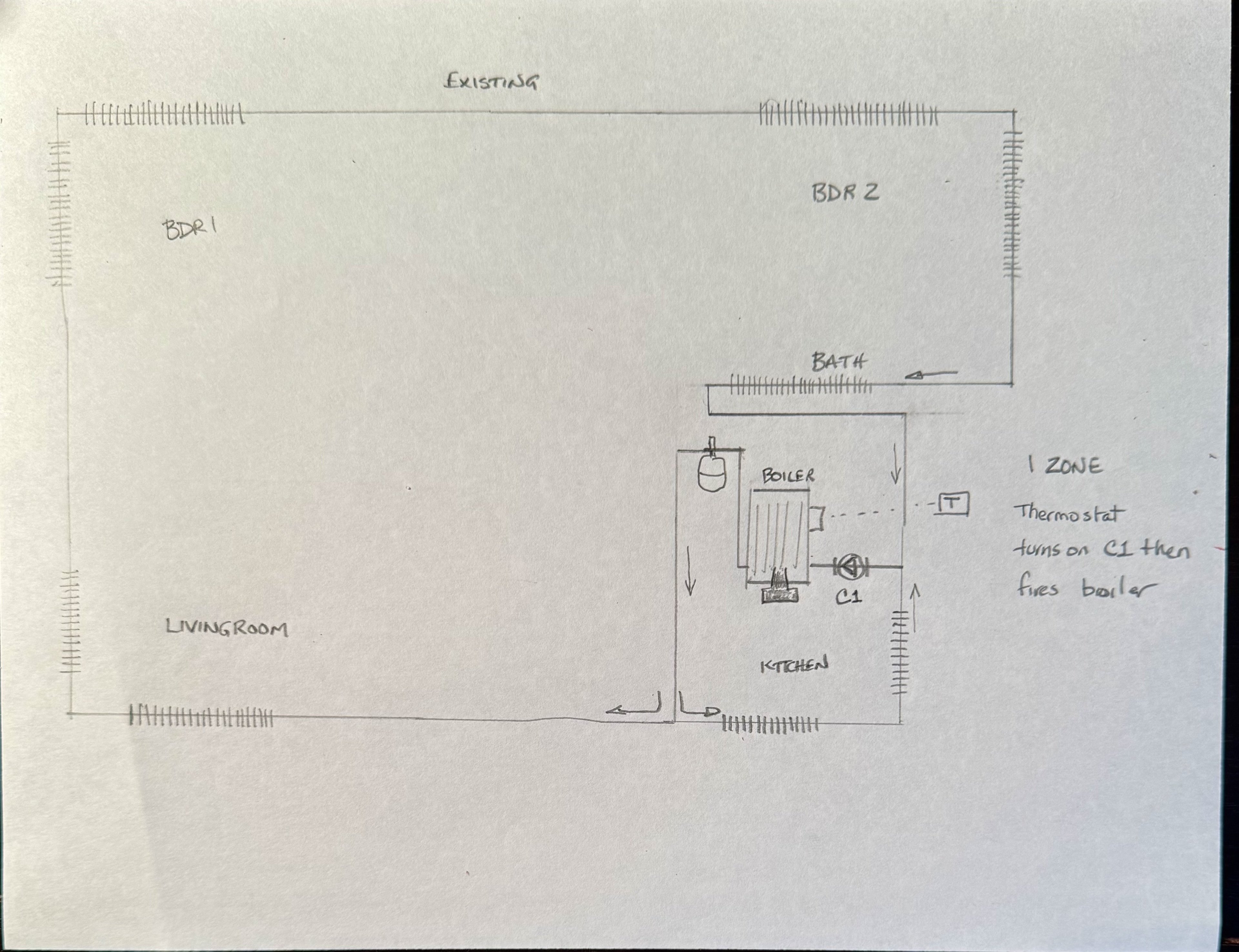
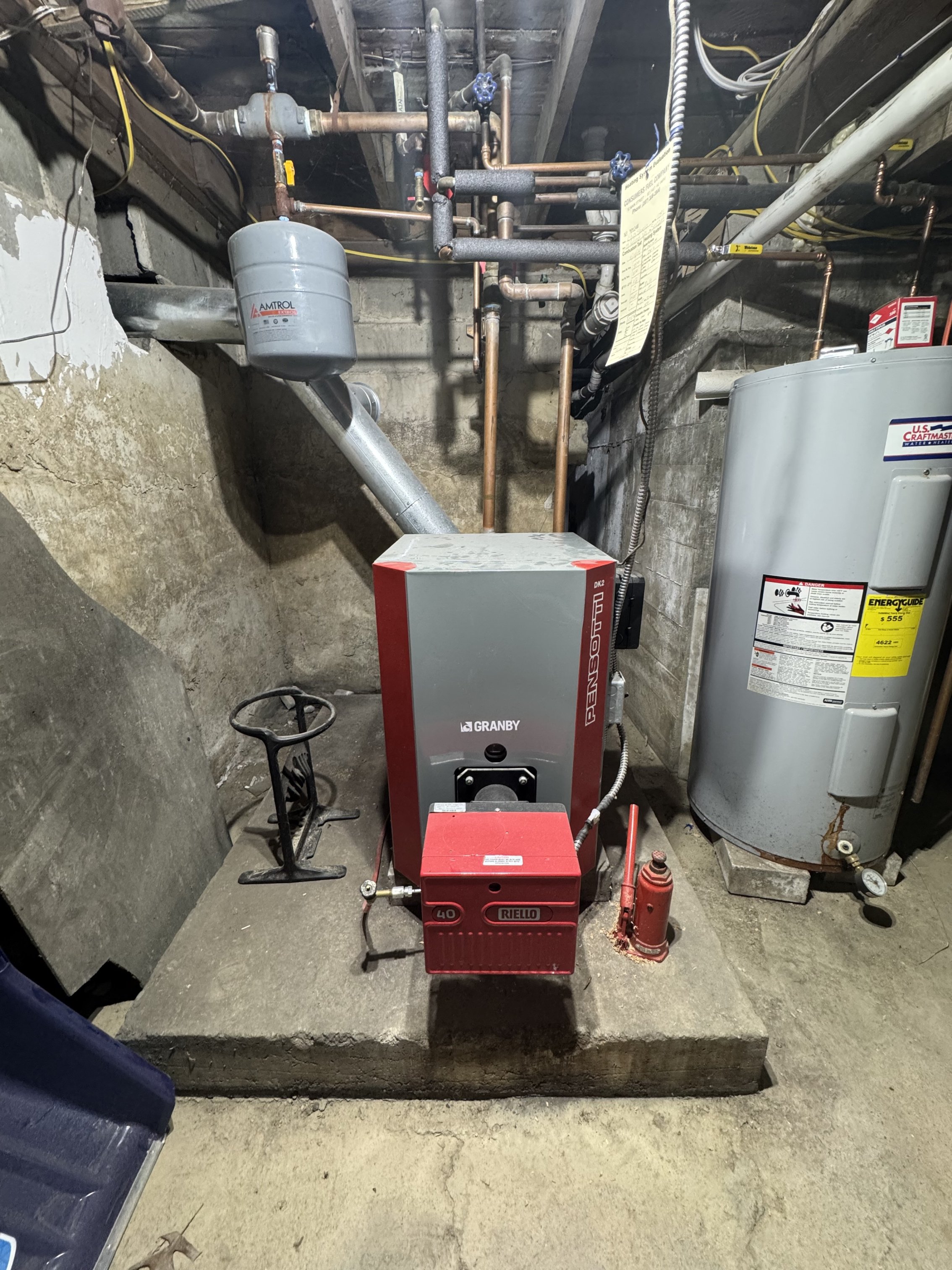
Existing system is 1 zone fin tube with condensing boiler see pics attached
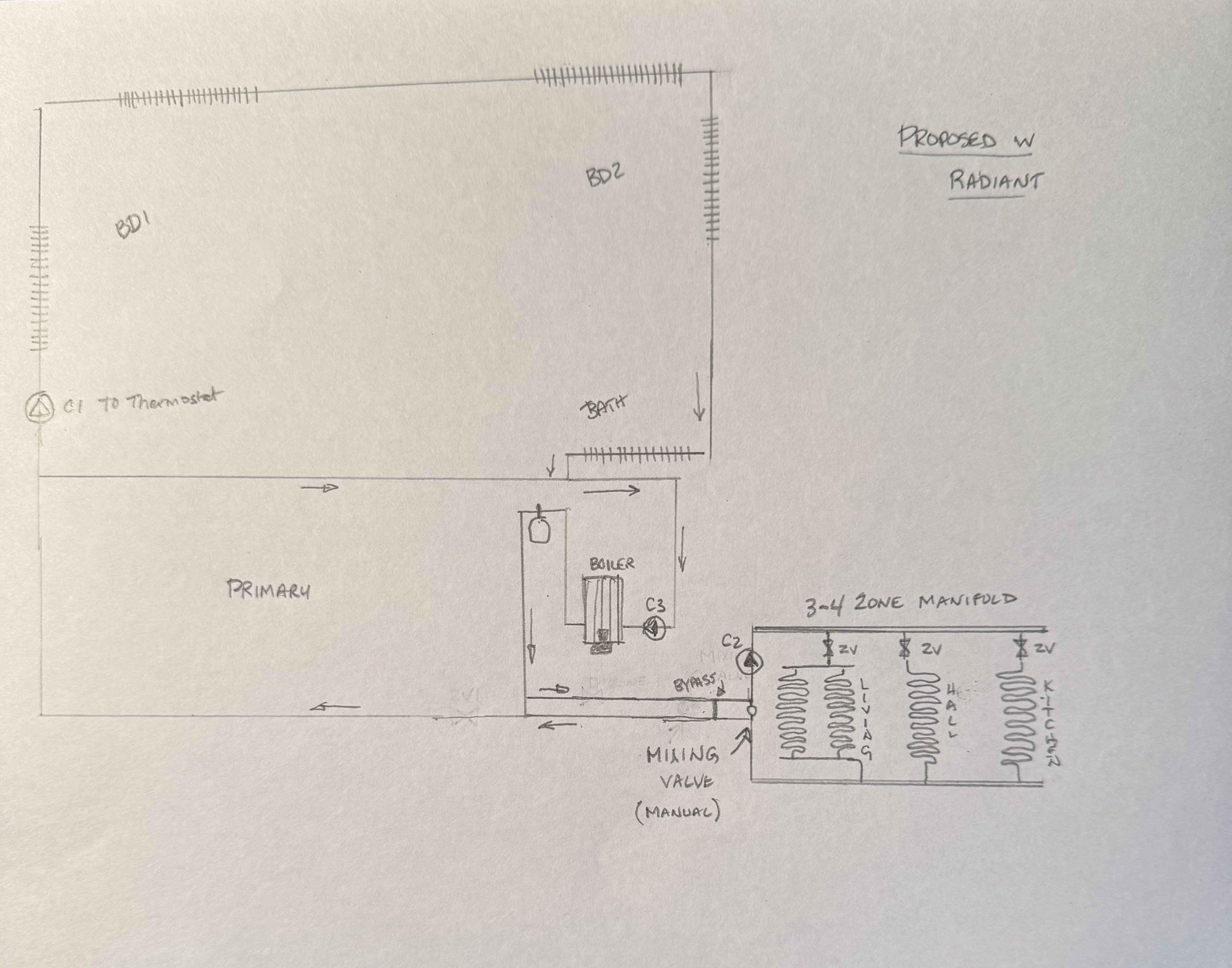
I already had to remove half the old loop for renovation reasons and would like to add a 4 zone manifold with underfloor PEX
Trying to understand the controls for the circulators and thermostats.
Questions:
- does primary loop need to be a specific length vs the circ pump
- In my “to be” pic does C3 need to run continuously?
- How to determine pump size for each circuit?
all feedback appreciated
Comments
-
What kind of boiler do you have? Atmospheric? Condensing?
If your house is under 4,000 square feet, a Taco 007 or Grundfos 15-42 should work.
 8.33 lbs./gal. x 60 min./hr. x 20°ΔT = 10,000 BTU's/hour
Two btu per sq ft for degree difference for a slab0 -
condensing boiler
0 -
Not a condensing boiler.
Look at the vent pipe. A condensing boiler would use a plastic vent pipe because all the flue gas condensation would rot the galvanized vent connector away in a year. According to the manual this is a better way to do the near boiler piping if you want less problems with air in the system.

Assuming that you are connecting to standard Baseboard heating units with 3/4" copper tube. The circulator on the return indicates the installer didn't read the manual and followed the directions his father who taught him to do it that way.
Edward Young Retired
After you make that expensive repair and you still have the same problem, What will you check next?

 2
2 -
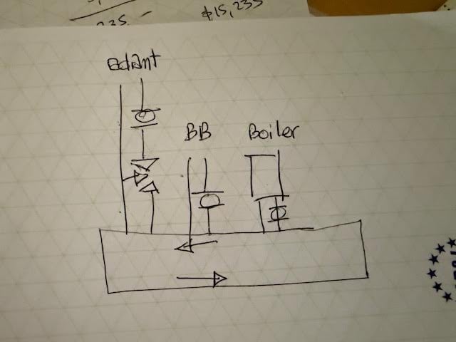
here are a couple ideas and a link to an article explaining them.
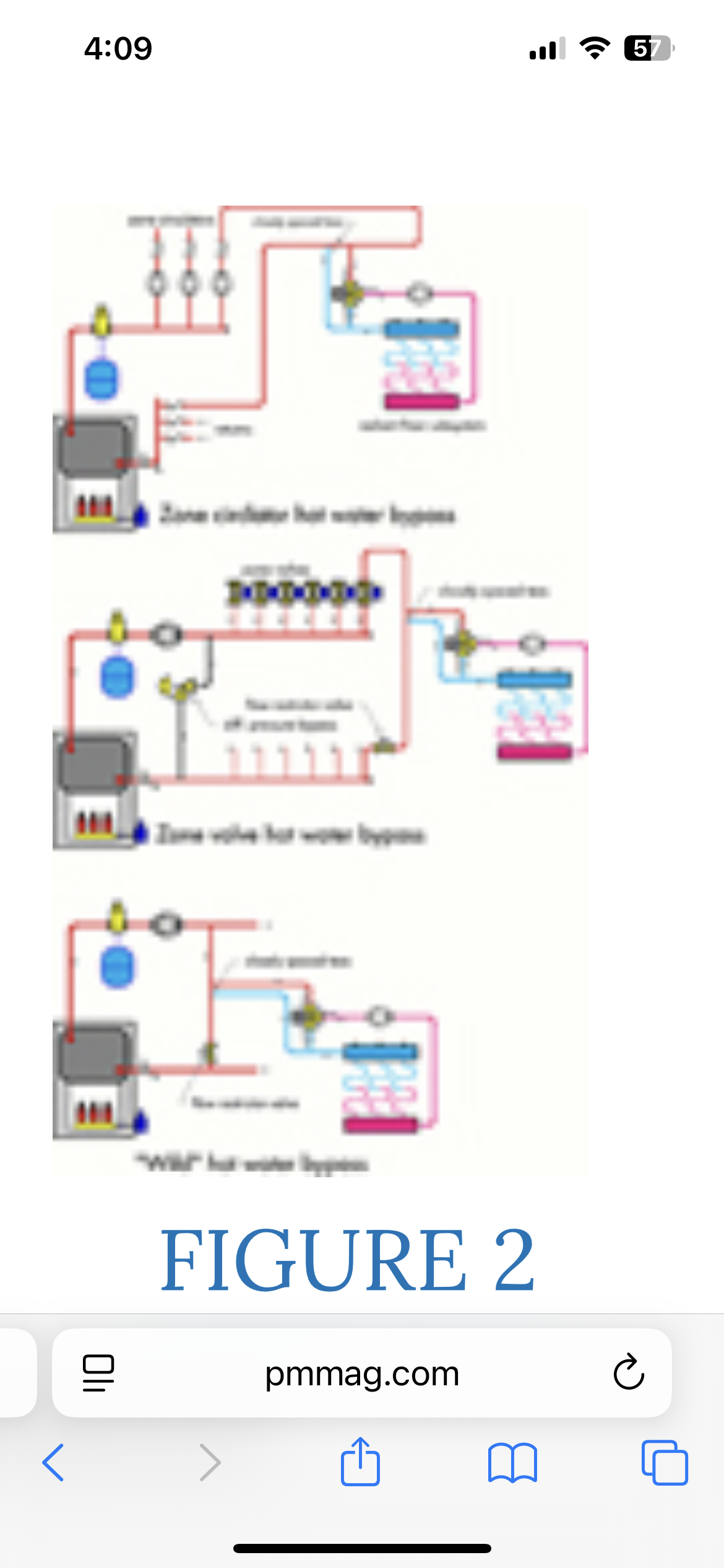 Bob "hot rod" Rohr
trainer for Caleffi NA
Living the hydronic dream0 -
Now adding a radiant floor zone to your existing system will require draining water from the boiler (so you may want to upgrade your near boiler piping at this time) and connecting the zone this way. This is the bare minimum that will work.
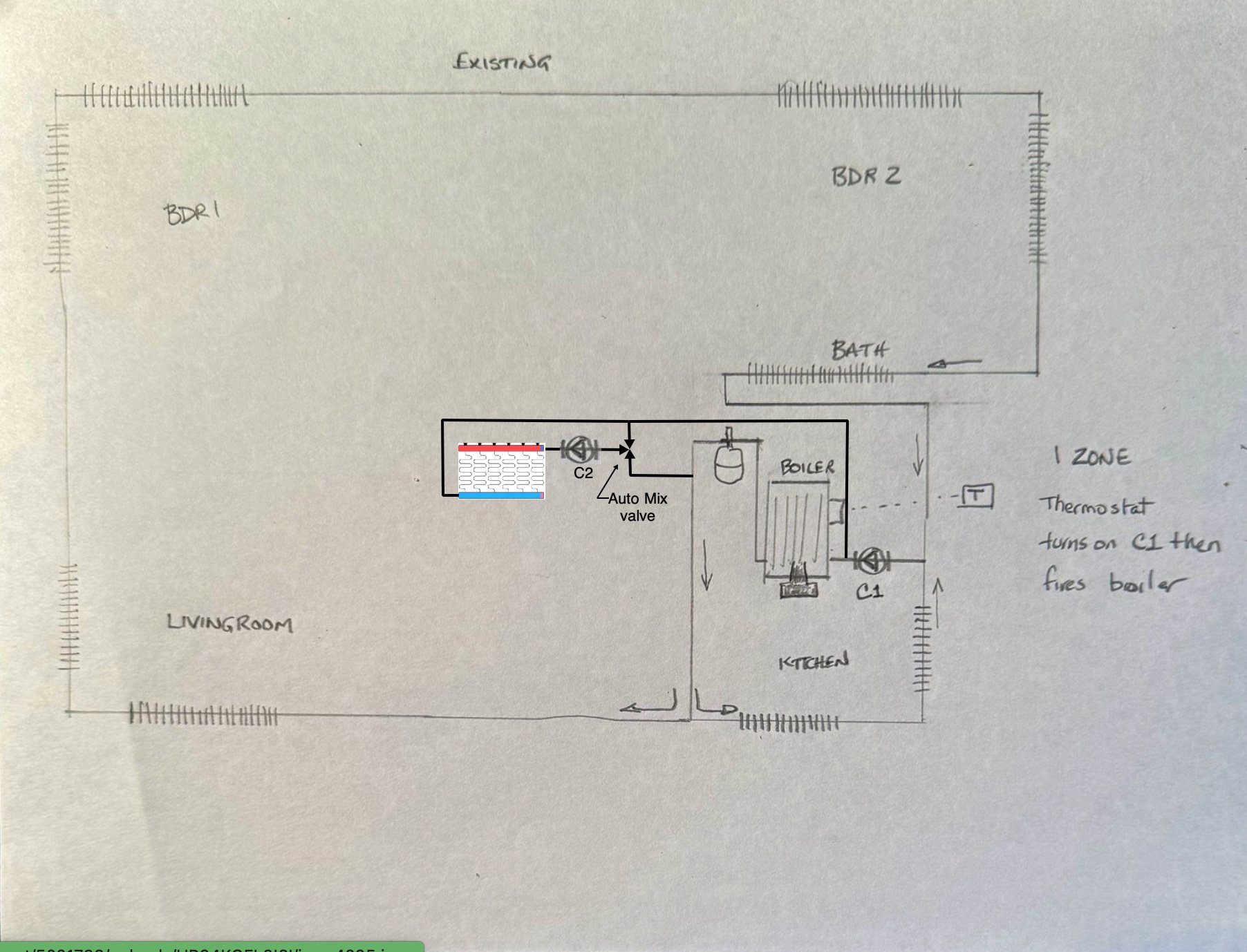
The controls will need to be added so when thermostat that operated C2 calls for heat , C1 will not operate but the burner will operate. depending on what is currently controlling the boiler, that can be done with a ZC or ZR terminal and a Taco SR501 or equal. Or a Taco SR 503 or equal.
I can draw you the wiring diagram if you want me to.
Edward Young Retired
After you make that expensive repair and you still have the same problem, What will you check next?
0 -
ed. Thanks for this info. A wiring diagram would definitely help me Thanks
0 -
Any Questions?
Edward Young Retired
After you make that expensive repair and you still have the same problem, What will you check next?
2 -
two questions:
- In the layout you provide above showing the secondary circuit shouldn’t they need closely spaced T’s?
- Does the mixing valve still protect the boiler in this case or is it simply reducing radiant floor circuit temperature?
0 -
Yes sorry that was a typo. Should be read NON condensing boiler.
also the Kitchen circuit in the lower right corner was removed and capped at both ends during renovations0 -
chippy2 Member Posts: 6
two questions:
Q: 1. In the layout you provide above showing the secondary circuit shouldn’t they need closely spaced T’s?
A: This is a layout that will work without too much repiping. just adding a zone that is connected to the supply and the return. if you are going to get more involved with a piping redesign
Q: 2. Does the mixing valve still protect the boiler in this case or is it simply reducing radiant floor circuit temperature?
A: No that layout does not have boiler protection. That layout is "The Minimum" you must do. I think @hot_rod Bob's post has some better layouts. too bad they are a little out of focus but the link is still good.
Edward Young Retired
After you make that expensive repair and you still have the same problem, What will you check next?
0 -
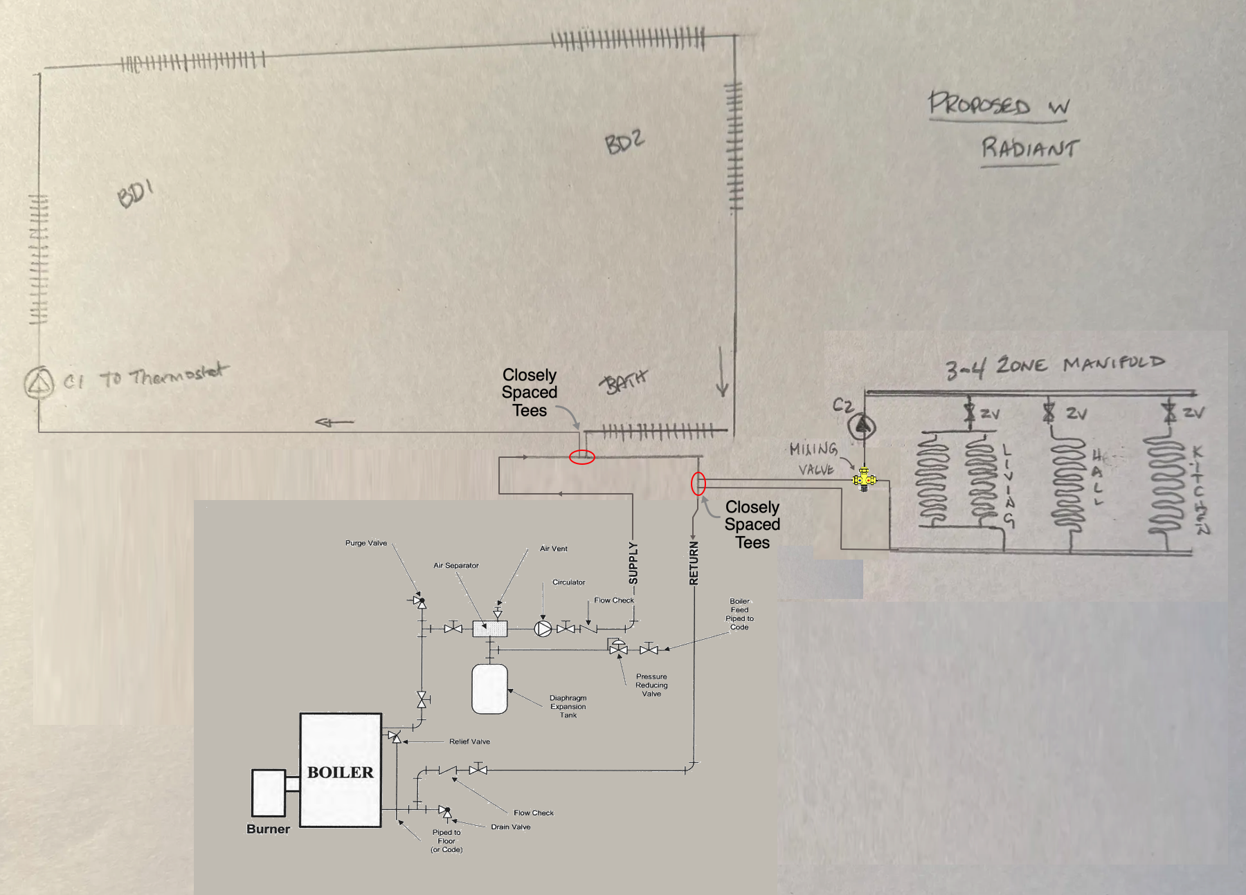
Since you have baseboard hot water radiators, there is not much water volume in your system. For that reason you never actually needed boiler temperature protection. The return water heated up quickly. By adding a low temperature radiant heat zone, then you will be returning much colder water if only that zone is operating. So this is a redesign that I might use. In your "proposed" drawing the radiant heat zone circulator will not get any hot water from the boiler unless the boiler C3 is operating to move heated water past the closely spaced tees. Whenever C3 is operating there will be a tendency for the baseboard loop to get some ghost flow or thermocycling or even forced flow even though C1 is not operating. that is because the baseboard loop is not connected to the primary boiler loop
I didn't see your proposed diagram when I first looked at your post. That is why I offered the "Minimum Diagram". Now that I can see that you are using three circulator pumps, I will offer you this diagram with four major corrections.
- I have pasted the near boiler piping from the I/O manual from Pensotti.
- I have corrected the closely spaced tees. The idea is to have next to zero pressure drop between the supply to and the return from the secondary loop. By putting one of the Tee fittings on the corner of a run in the primary loop, you are creating a pressure difference between the supply to and the return from a secondary loop.
- I have placed the hotter secondary loop first on the primary loop. The second lower temperature secondary loop will be able to operate with lower temperature water from the first secondary loop’s return. Since both primary and secondary can operate at the same time and also only one at a time, the water temperature feeding the low temperature secondary loop will be different if the high temperature loop is operating or is not operating. Since this happens without notice, the manual mixing valve idea will not work so that brings me to fix #4
- Install an automatic mixing valve.
I hope you find this helpful
Mr. ED
Edward Young Retired
After you make that expensive repair and you still have the same problem, What will you check next?
1 -
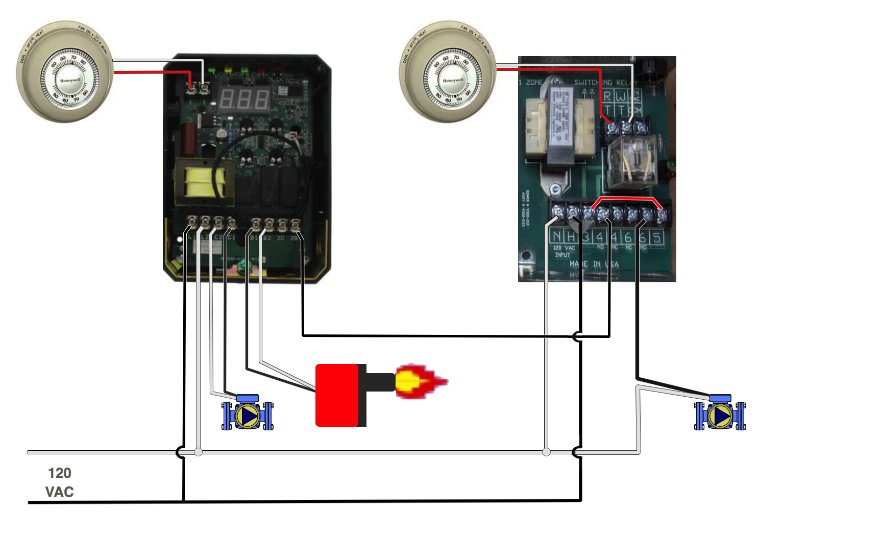
I would purchase a Taco SR 502 (or 503) to operate the zone one and the zone 2 circulators separately using separate thermostats. Here is that diagram
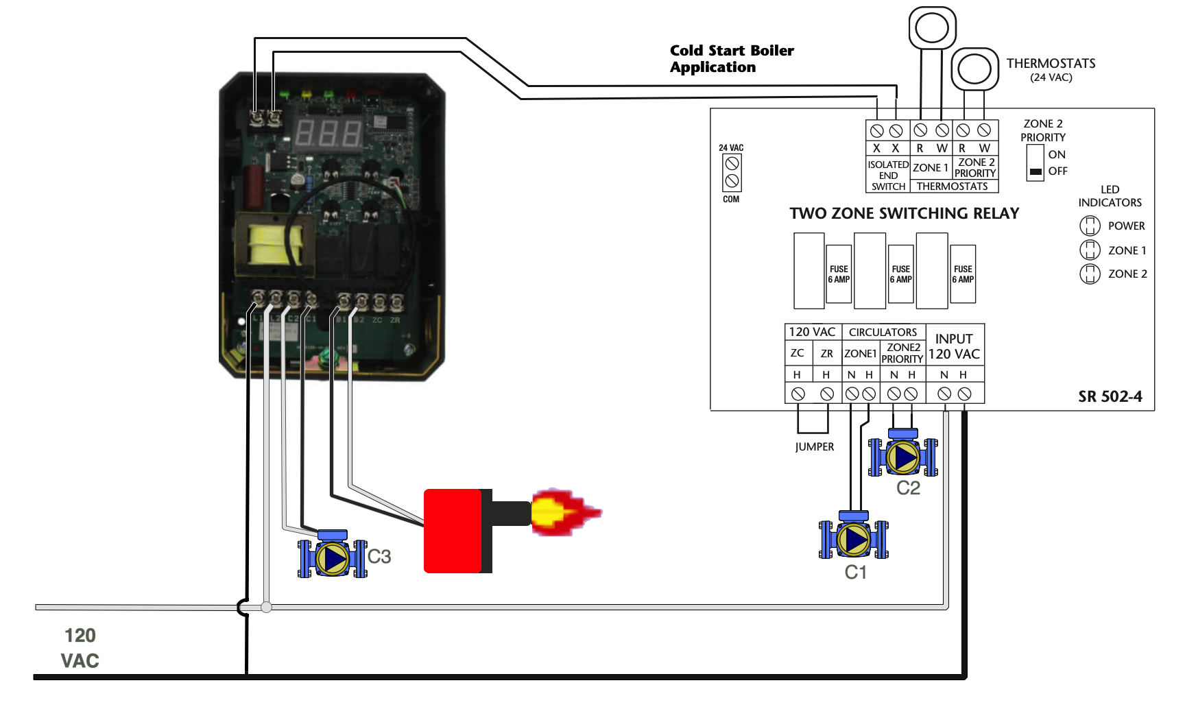
Any Questions?
Edward Young Retired
After you make that expensive repair and you still have the same problem, What will you check next?
 1
1 -
Ed thank you. I don’t see you updated diagram that you are describing 🙁 I do see the control circuit however
0 -
Oops… I edited my previous post with the diagram.
Edward Young Retired
After you make that expensive repair and you still have the same problem, What will you check next?
0 -
if the radiant us around 10% of the boiler btu output , I would not be concerned about return protection
Bob "hot rod" Rohr
trainer for Caleffi NA
Living the hydronic dream0 -
the radiant floor circuits will cover about the same square footage of floor space as the existing, remaining sq footage of floor space that the baseboards are heating
Using aluminum trax under floors 1/2” PEX
was looking at the Caleffi mixing station W three zones and the Taco 5030 -
Ed sorry to bother. Maybe I’m not seeing it but, I still don't see a diagram you updated ( even when I follow your latest link?)
What / how am I missing it?
Can you repost it one more time? Thank you!
0 -

I don't know why it is not coming up on my edit. Here is it in a new comment
Edward Young Retired
After you make that expensive repair and you still have the same problem, What will you check next?
0 -
got it thanks!
0


Categories
- All Categories
- 87.6K THE MAIN WALL
- 3.3K A-C, Heat Pumps & Refrigeration
- 59 Biomass
- 429 Carbon Monoxide Awareness
- 124 Chimneys & Flues
- 2.2K Domestic Hot Water
- 5.9K Gas Heating
- 119 Geothermal
- 168 Indoor-Air Quality
- 3.8K Oil Heating
- 78 Pipe Deterioration
- 1K Plumbing
- 6.6K Radiant Heating
- 394 Solar
- 16K Strictly Steam
- 3.5K Thermostats and Controls
- 56 Water Quality
- 51 Industry Classes
- 50 Job Opportunities
- 18 Recall Announcements