Correct location to install the CW makeup valve on a boiler

Hello all, Steve from the wonderful Catskill mountain park.
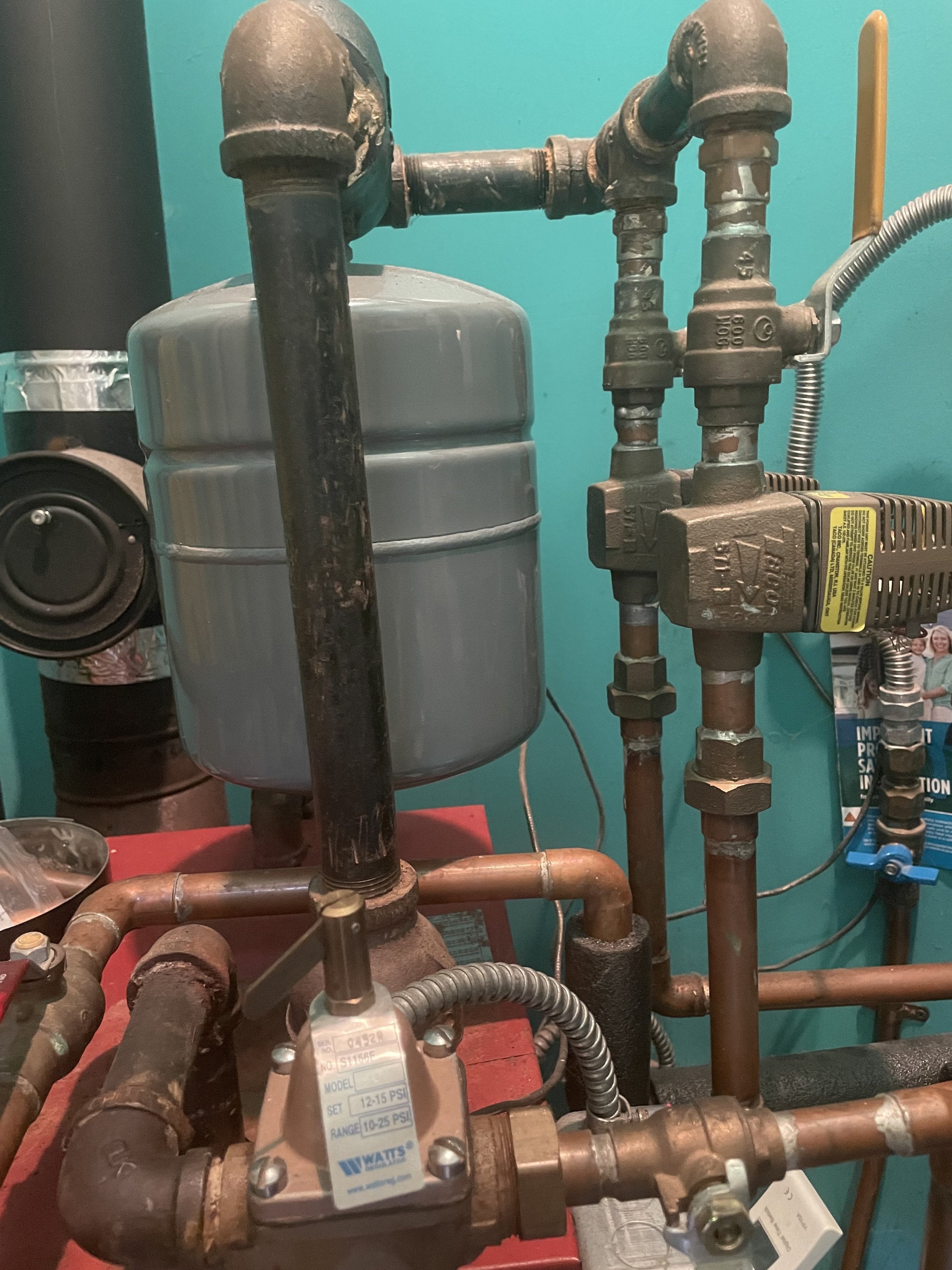
I have a question regarding a hot water boilers CW makeup valve location. The valve is currently installed into a 3/4" pipe on the top front of a hot water boiler next to the supply pipe. This pipe is another alternative location for the pressure relief valve which is installed at the recommended top rear location. I read an article that said feeding the CW at this top location directly into a boiler is not ideal and can be causing the excessive air problems. The directions for this boiler shows the PRV installed on the return end above the circulator. Would anyone recommend removing and reinstall the CW feed to the return end at the suction side of the circulator, or is the supply side near the expansion tank a better location?
Comments
-
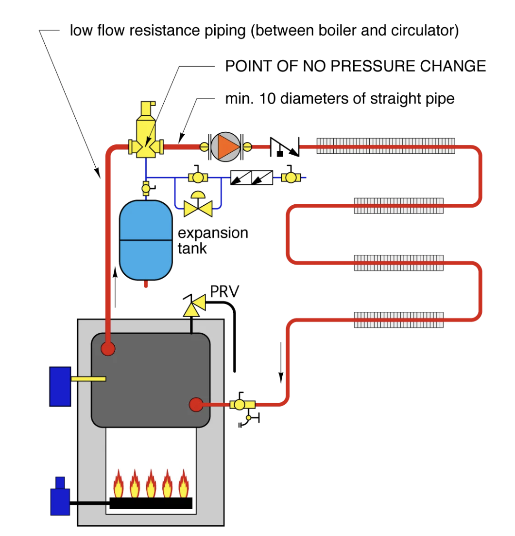
The water fill should connect at or near the expansion tank. And ideally the circulator is pumping away from the tank/ fill location. A backflow device on the fill valve also
A common piping example here:
 Bob "hot rod" Rohr
trainer for Caleffi NA
Living the hydronic dream0 -
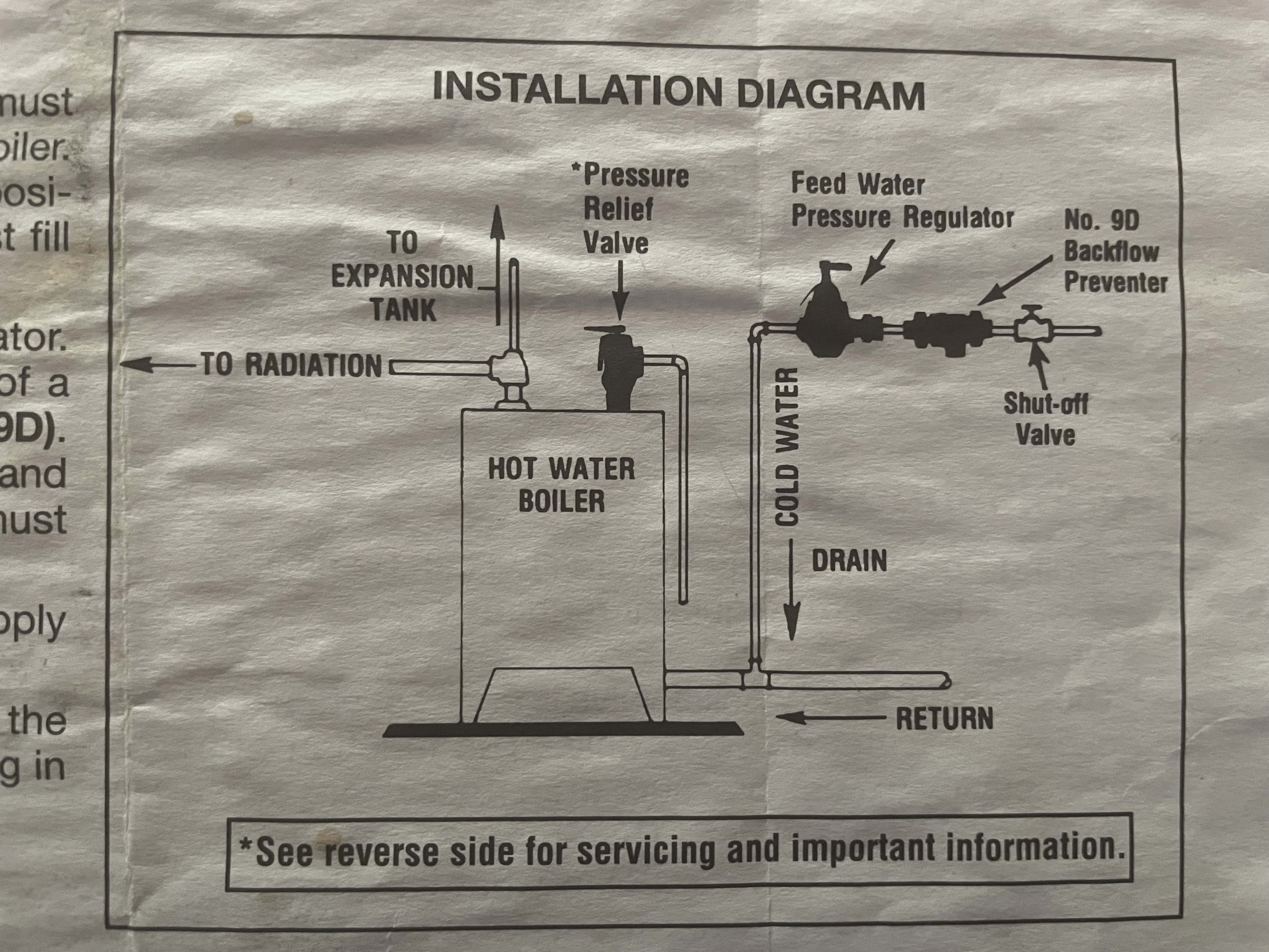
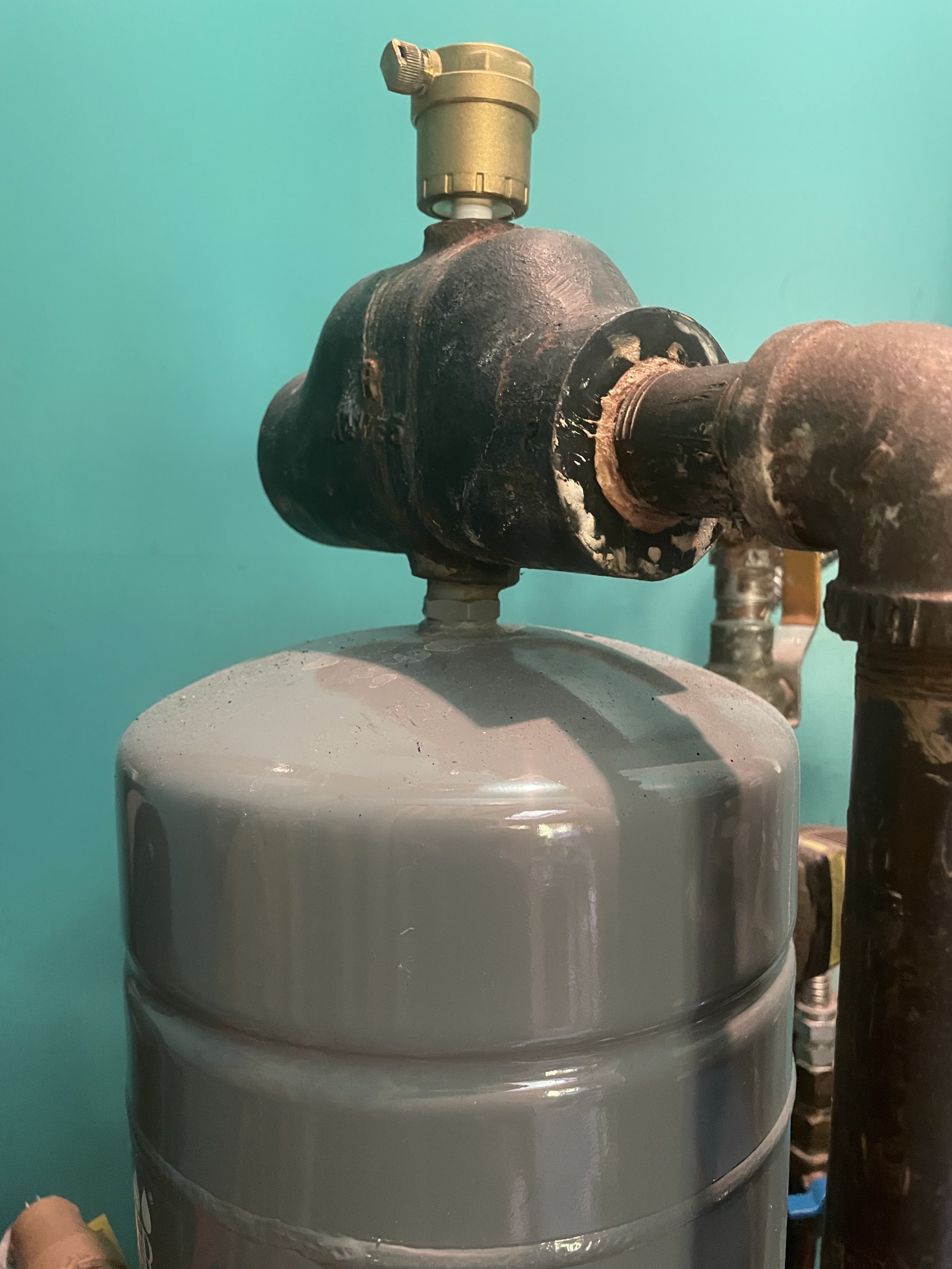
Thanks Hot Rod. This boiler was shipped with the circulator on the return side. The supply side has a Watts air scoop with the expansion tank below and air vent on top. There are two zone valves on the supply side after the expansion tank. The Watts air scoop doesn't have the side tap. I could install a 1/2" T between the scoop and tank and feed the CW makeup there? Would that be better than using the return side or where it's currently feeding through the top of the boiler? I included the boiler and feed valve recommendations as well as the air scoop and tank.
 0
0 -
Yeah, there are many hydronic systems out in the wild with pumps on the return, air purger and expansion on the boiler supply.
Hydronic "best practices" would have the expansion tank located at the inlet of the circulator..
So in your case you would need to either move the circ up after the air purger on the supply
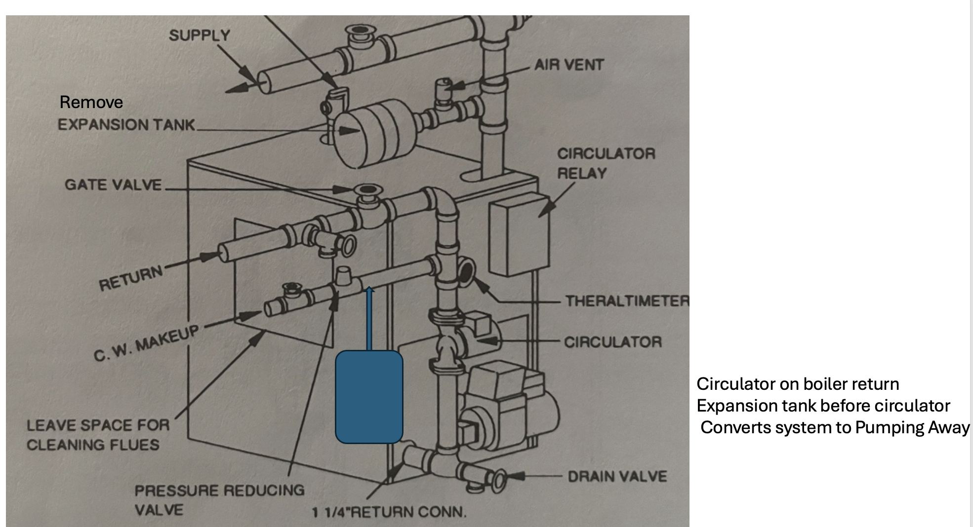
or move the expansion tank connection down before the circulator on the return.
If it works or has worked without any air noise issues you could leave it as is.
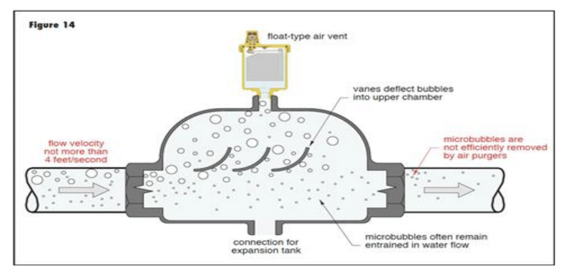
An example of the expansion tank moved to return. I'd like to see an air purger added to this drawing also. Float tytpe air vents positioned like shown do not remove air from fluid stream very well.
Your system does have a primitive, ramp type air purger :) Ideally a purger like yours has 12- 18" of straight pipe upstream.
 Bob "hot rod" Rohr
trainer for Caleffi NA
Living the hydronic dream0 -
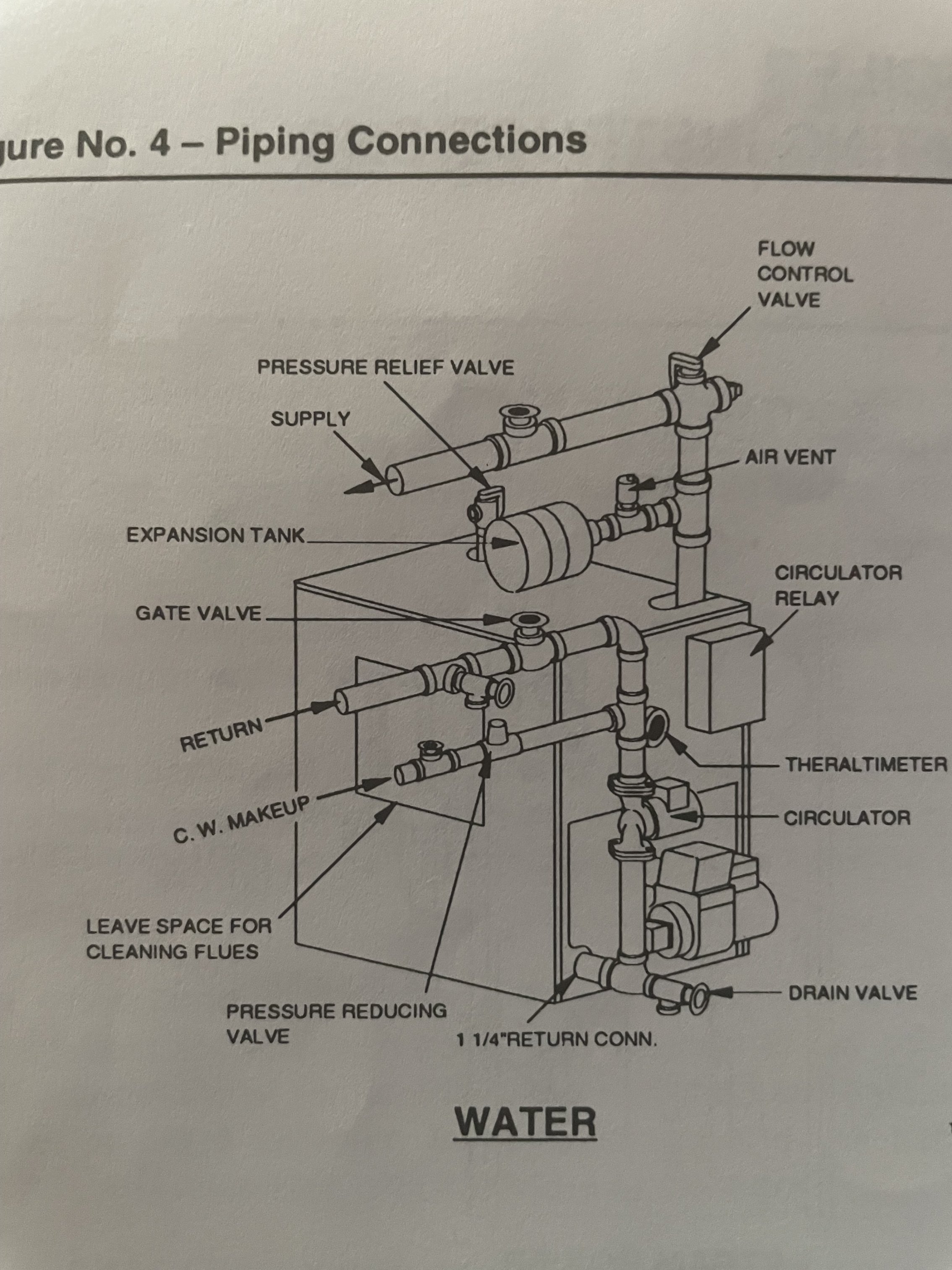
This piping arrangement is very old. It actually causes some problems in some systems. Many installers will use a pressure reducing valve (auto feed) on the CW supply to the boiler.
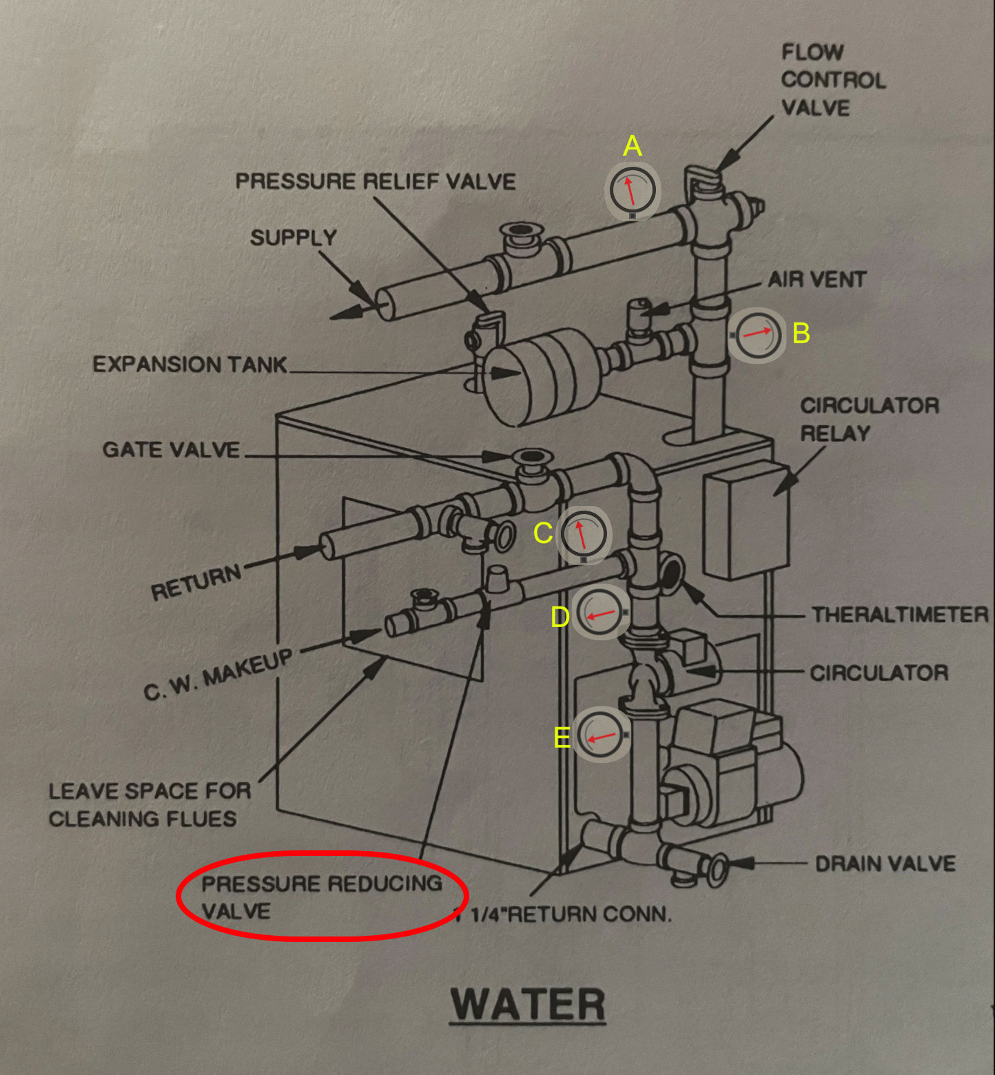
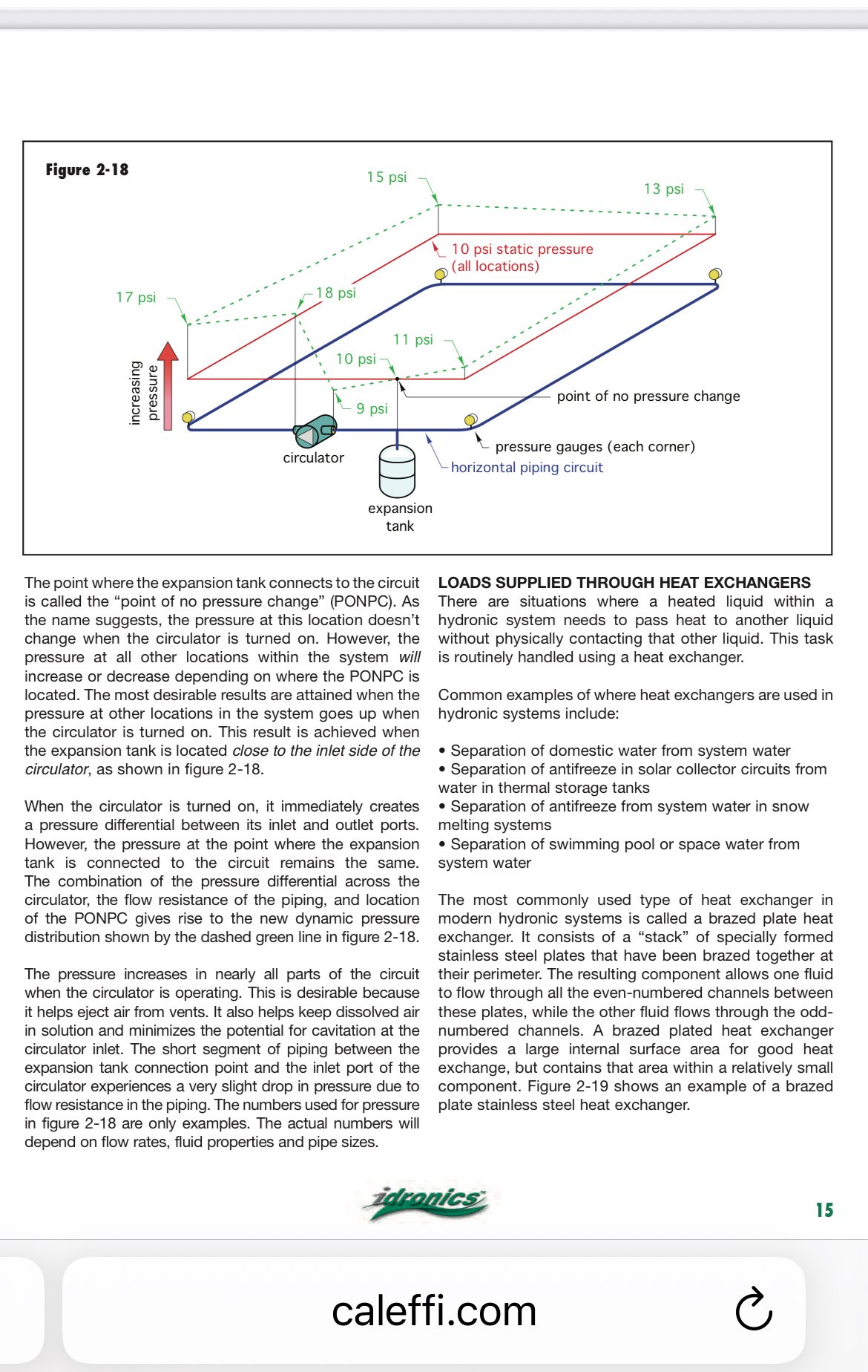
Imagine in your minds eye the pressure at these 5 locations (A, B, C, D, E) in this illustration. When you fill the system using the auto feed valve set at about 12 PSI. you have a system full of cold water and an expansion tank with 12 PSI air pressure so it has no water in the expansion tank. with the circulator pump off, all the pressure gauges will read close to 12 PSI.
Now what happens when the pump turns on?
There will be a pressure difference on either side of the pump. and if we assign a 6 PSI difference to that pump (your actual pressure difference may be different). Now it is a known fact that the expansion tank with 12 PSI in in is known as the Point Of No Pressure Change (PONPC) so unless you add water or air to the closed system OR you change the water temperature, there will always be 12 PSI at gauge B
Now if we allow for about 0.5 PSI pressure drop thru the boiler, when the circulator pump comes on the pressure at the pump outlet might change to 12.5 PSI on gauge E. That means that the inlet side of the pump will change to 6.5 PSI at gauge D.
What is the pressure at gauge C if the pressure at gauge D is 6.5 PSI? Probably 6.5 PSI. And what is the pressure reducing valve set to? 12 PSI right? Then what will the pressure reducing valve (Auto Feed) do it there is only 6.5 PSI on the side that is supposed to be 12 PSI? Add Water to make the inlet side of the pump 12 PSI, right?
If the pressure at the inlet side of the pump is 12 PSI then you add 6 PSI to the outlet side of the pump that will make it 18 PSI… Right?
That will cause more water to enter the system and that additional water has no place to go because the system is already full of water… so it ends up in the expansion tank at 18 PSI. Now there is less air space in the tank for expansion when the water heats up. so maybe the system will actually get close to 28 or 30 PSI because there is not enough room for the water to expand.
Now you have a boiler that is operating and the temperature increases and you end up with the following pressure gauge readings.
- A = 28 PSI
- B = 28.5 PSI due to the pressure drop thru the flow control valve (Aprox)
- C = 23 PSI due to the increase in pressure as a result on heating the water
- D = 23 PSI for the same reason as C
- E = 29 PSI as a result of the increase in pressure folr the pump operating against the PONPC and the 0.5 pressure drop thru the boiler. (all hypothetical numbers)
And every once in a while the pressure relief valve weeps a little water. Eventually the relief valve fails to close completely and you have a leaking valve that needs to be replaced and you can't figure out why they keep going bad every other year, while the water heater relief valves lasts over 10 years without. problem.
That old diagram is a relic from back when pump seals were made of heat sensitive fibrous material so all the pumps were placed on the cooler return piping. Move into the the 21st century and place your pump so the expansion tank is on the inlet of the pump.
Edward Young Retired
After you make that expensive repair and you still have the same problem, What will you check next?
0 -
Ed is on the correct path
To find exact numbers to the pressures at various points you would need to define the circuit, hydraulically speaking.
How many feet of piping, how many fittings and valves, etc
In some cases you could be sub atmospheric in points of the system. A condition you can and should avoid with proper component placement
Here is a visual of
pumping away, on a hypothetical circuit
Bob "hot rod" Rohr
trainer for Caleffi NA
Living the hydronic dream 1
1 -
Thank you Hot Rod and Ed. The detailed explanation of pressure differences makes sense as to why the pressure would rise.
There has been a definite increase in pressure on this boiler since the 007 circulator pump was upgraded with a newer 007e model. The pressure relief valve did start weeping and then popped after the new pump was installed. I thought the pressure reducing valve was stuck open as I've cleaned it once before. I bought a new PRV and planned on replacing it as well as moving the newly installed pump to the supply side.
This boiler always had an air issue and needed to be bled regularly. The pressure only fluctuated between 12-18 psi. The air issue worsened and the pressure began to rise higher when the new pump was install. It appears as though the new pump may have amplified an existing problem?
I have a new cold water PRV which I'll be installing first. If the pressure is still rising higher than the set 12-15 psi, i planned to reinstall the old 007 pump to see if the increased high pressure fluctuations become lower again.
As i mentioned, the PRV was installed into a 3/4" tap on top of the boiler just to the left of the supply. This location was meant as an alternative place for the pressure relief valve and not the CW makeup. I don't know if introducing cold water to the top of the boiler is causing a problem?
Since I'll be moving the pump to the supply side, should i also move the cold water PRV to the supply side or leave it as is in the top of the boiler?0 -
The fill valve connects at or close to the expansion tank.
If the expansion is staying at the supply where it is now, a tee below it would be one option.
It would be an option to connect the tank into a boiler connection at the top. There is very little flow resistance between the boiler and tank location, a foot or so of large pipe.
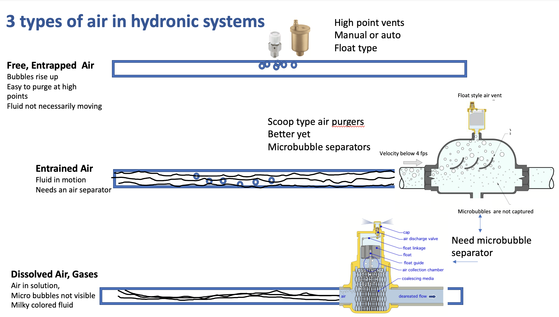
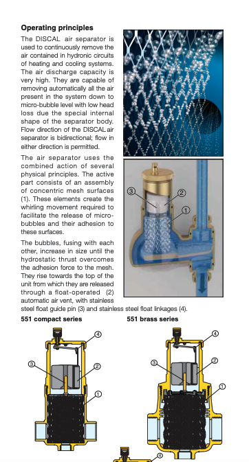
If it were me I would replace that scoop air purger with a Discal or other. That type of air purger, installed like that, with little straight pipe upstream, is not very effective. Since you have had chronic air problems, may as well do the upgrade.
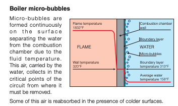
Microbubbles form inside the boiler everytime the flame hits the cast iron. Unless they are completely eliminated they go in and out of solution as the water heats and cools. The pic below shows a cross section of a boiler casting
The microbubble type air separators all have a media inside that quickly grabs those bubbles.
With your air scoop the tiny bubbles just blast through.
Here is a look at the two principles.
 Bob "hot rod" Rohr
trainer for Caleffi NA
Living the hydronic dream0 -
I was looking at alternative air separator's and going to ask for some suggestions. I planned to remove the Watts air scoop, vent, and tank to make room for the circulator and new air separator. Do you have a suggestion where to install the PRV cold water feed?
Your option to move the expansion tank directly into the boiler would also help make room. I thought the expansion tank had to be on the supply side before the circulator?
If installing it directly into the boiler is a good option, i suppose i could use the 3/4" tap on the top front of the boiler (currently used for the cold water PRV) for the tank. I could install a 12" straight pipe with a 90 degree 3/4" to 1/2" reducer to side mount the tank.0 -
I was reexamining Ed's explanations based on the old diagram I provided from the boiler manufacturer. Two differences on this boiler are the cold water pressure reducing valve is connected to the top of the boiler next to the supply piping. There is also no flow control valve which is shown in the diagram. I'm unsure how this will change your example regarding PSI changes. One question i had was if moving the CW makeup to the expansion tank will be a better choice instead of directly into the boiler. Before moving the circulator to the supply side, I want to reinstall the old Taco 007 pump. The system pressure increase began when the new Taco 007e was installed last year.
0

Categories
- All Categories
- 87.6K THE MAIN WALL
- 3.3K A-C, Heat Pumps & Refrigeration
- 59 Biomass
- 429 Carbon Monoxide Awareness
- 124 Chimneys & Flues
- 2.2K Domestic Hot Water
- 5.9K Gas Heating
- 119 Geothermal
- 168 Indoor-Air Quality
- 3.8K Oil Heating
- 78 Pipe Deterioration
- 1K Plumbing
- 6.6K Radiant Heating
- 394 Solar
- 16K Strictly Steam
- 3.5K Thermostats and Controls
- 56 Water Quality
- 51 Industry Classes
- 50 Job Opportunities
- 18 Recall Announcements