Delay of boiler firing?
Comments
-
That's thermostat calling for heat hours, not boiler firing time.
Also it's a bit less as I have a 10 minute delay between the thermostat and boiler.
The thermostat duty rate setting isn't right and Honeywell was of no help with fixing it. So it'd call for heat and a few mins later be satisfied, and constantly do that.
10 min delay means the boiler won't fire unless the t stat has called for heat for at least 10 mins... ie, heat is truly needed.
0 -
I can't edit but I meant to say boiler won't fire and pumps won't run.
 1
1 -
Once you get back to your equipment location, we can get down to the specifics. That is when you can get all the information needed. I believe that @hot_rod will have joined by then. I think that this will be a HX that will work for you. B&G BP400-20LP should do a modest size radiant floor system. It will handle whatever the 80K boiler can do. Your Oil heater needs to have the capacity, And I believe it is at least that big or more!
Edward Young Retired
After you make that expensive repair and you still have the same problem, What will you check next?
 1
1 -
With 140* oil boiler temp, you're not getting 130* on the other side with a 20 plate 3x8 like the BP400. 180* oil boiler temp absolutely, but not 140*- that's 40 plate 5x12 territory
0 -
Agree with your information.
So will 120° for the radiant floor system work with that HX? 140° is a minimum or Low Limit setting for that system assuming that the oil boiler has a L8124 aquastat relay. then I would set the high limit to 160° or 170° That means the circulator from the oil boiler to the HX will not operate unless there is a call for heat at T T and the water temperature is above 140°. If I understand how that control works after over 45 years of working on them.
If @nate379's heating system required a higher temperature for baseboard or CI radiators, I might recommend a higher minimum temperature. What do you think the minimum temp. should be for the oil boiler in this case, and is the 160° high limit too low @GroundUp?
Edward Young Retired
After you make that expensive repair and you still have the same problem, What will you check next?
0 -
I was figuring a standard 160* on,180* off setup.
0 -
That will work, however the control you have on your boiler will determine whether you have a low limit (like the L8124) to maintain boiler temperature or if you need to add a low limit aquastat (to a L8148) to maintain boiler temperature. Once you get back to the boiler and send the specifications, we can address the needed controls and wiring you require. I am just hoping that you have the two stage heat T6 thermostat. If your thermostat has only one stage of heat, then you may need get a second thermostat as you suggested in an earlier post.
Edward Young Retired
After you make that expensive repair and you still have the same problem, What will you check next?
0 -
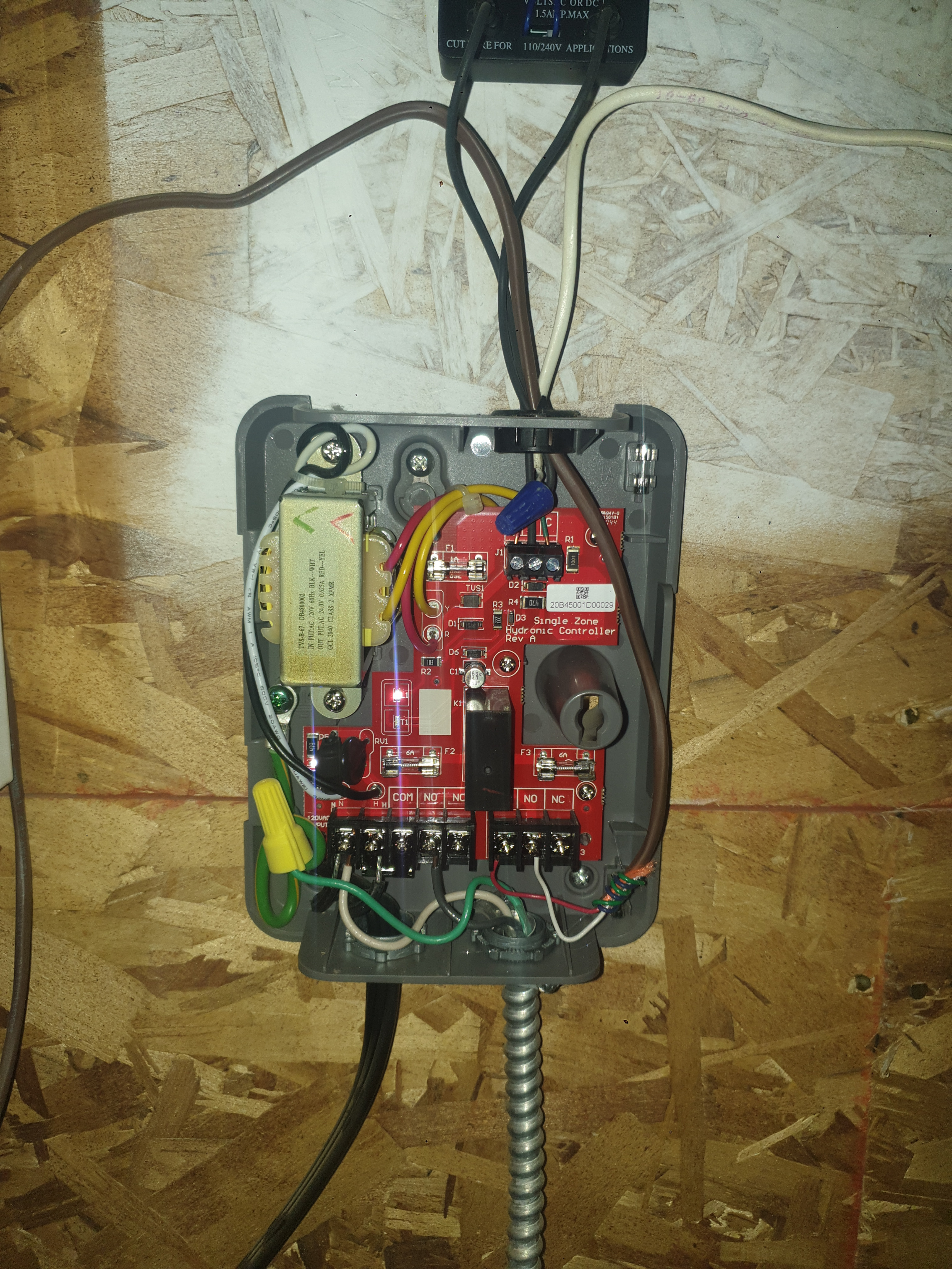
3250 Hydrostat
 2
2 -
T9 Honeywell.
Can do multistage
2 -
Do you know what the thermostat is connected to so the Vesta boiler operates for the floor heat? The Thermostat is a T6 from Honeywell? I can't find a T9.
Edward Young Retired
After you make that expensive repair and you still have the same problem, What will you check next?
0 -
Once I know how the thermostat is connected to operate the boiler, I can finish this diagram to see if the control logic will work.
This is the HydroStat 3250 added to the diagram with the L7284U to operate the burner.
Edward Young Retired
After you make that expensive repair and you still have the same problem, What will you check next?
0 -
Yes Honeywell T9
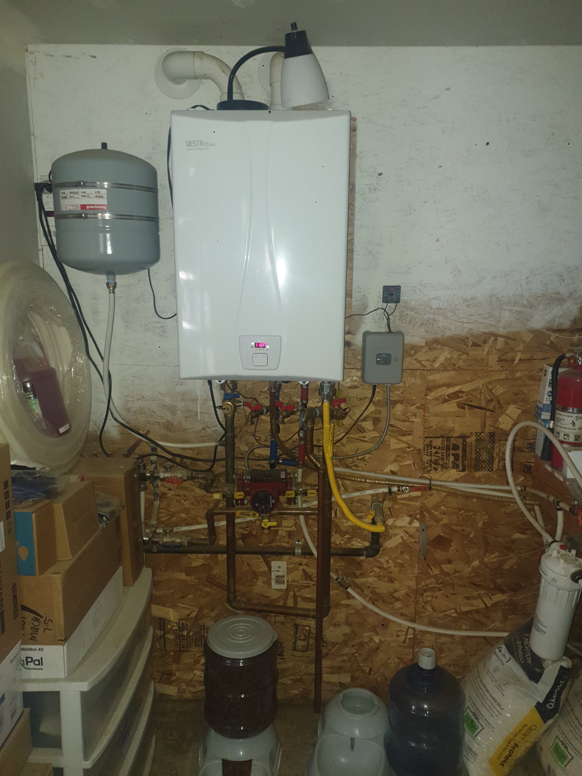
I'll get photos in a couple days.
0 -
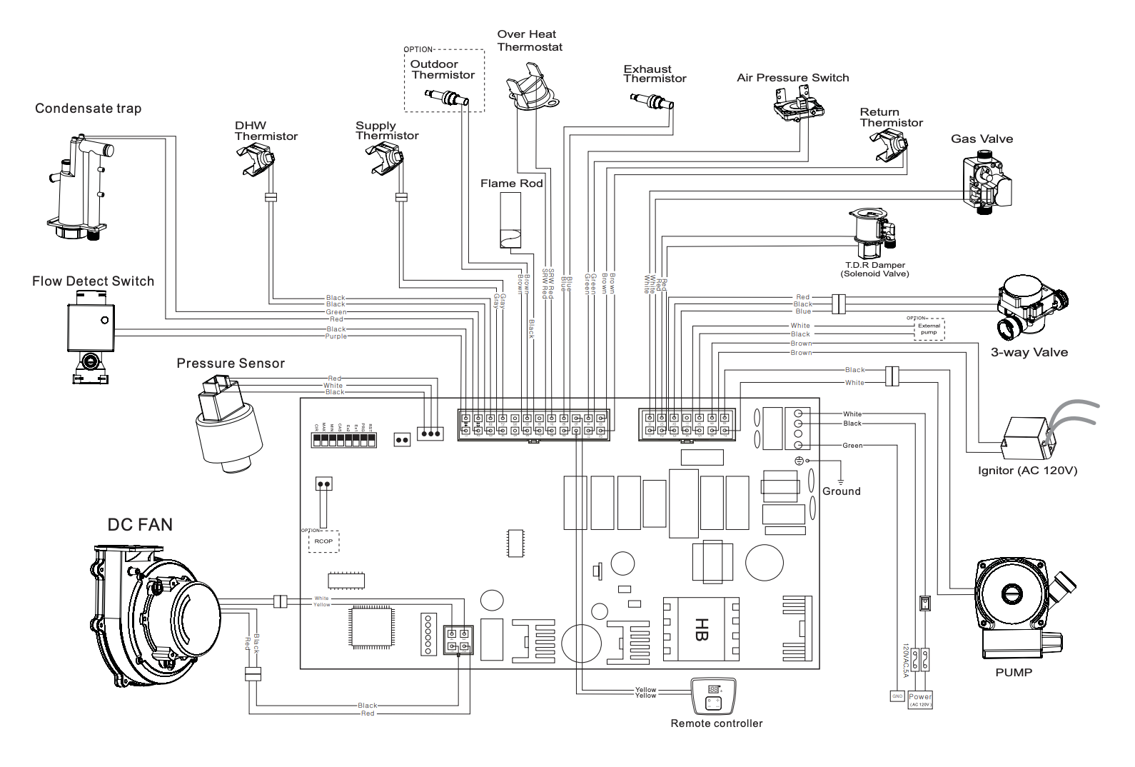
OK. You have a T9 thermostat that has at least 2 stages of heat. Right now that T9 is operating the Vesta boiler. Where is that T9 Red R wire connected to, and where is the T9 White W wire connected to, and where is the T9 C wire connected to? I can not see anyplace on the Vesta Boiler to connect a T9 thermostat to.
Vesta wiring diagram: Shows no place to add a room thermostat.
Edward Young Retired
After you make that expensive repair and you still have the same problem, What will you check next?
1 -
Maybe "remote controller"? It's odd thermostat isn't listed, not sure of an application that wouldn't need a thermostat.
Interesting it shows an outdoor temp sensor. Like an outdoor reset. I had looked into it a while back and had no luck finding one. I've been manually adjusting the water temp. If it stays at the 130* winter setting, it overheats the building in spring and fall.
It'll run during the night, and by day a bunch of heat is it the slab when it's not needed.
0 -
"It's odd thermostat isn't listed, not sure of an application that wouldn't need a thermostat."
Yes and you have a T9 thermostat connected to it somehow? So when you get there, can you look at the actual wires from the T9. R W C and tell me where they connect on the other (boiler room) end?
Edward Young Retired
After you make that expensive repair and you still have the same problem, What will you check next?
0 -
-
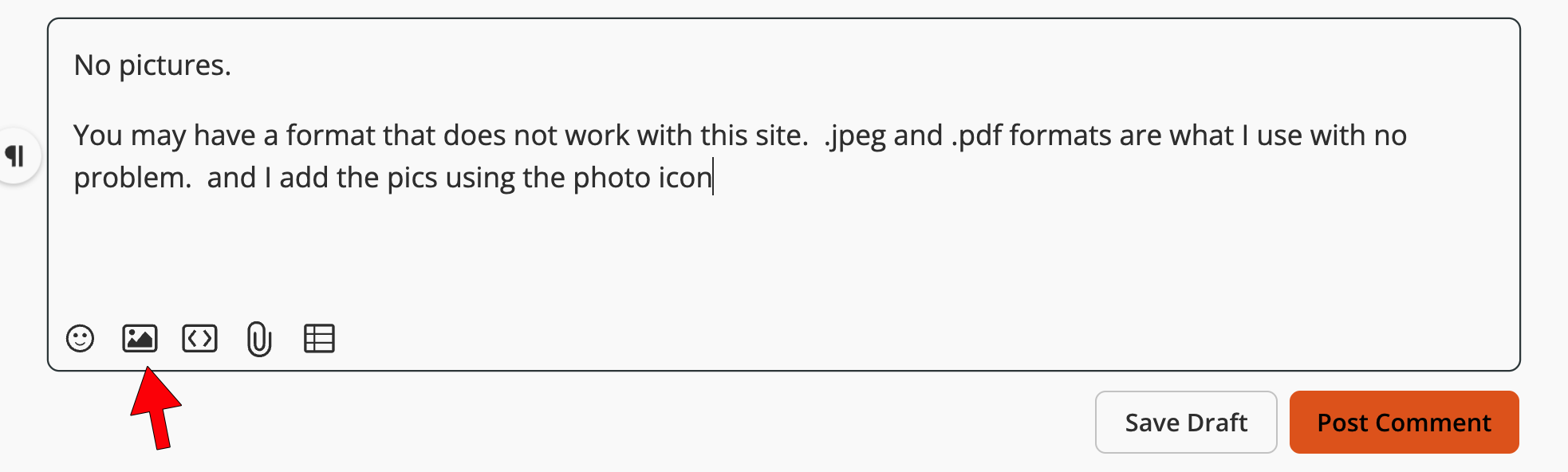
Are the pics showing? Seems to just load at orange dots.
0 -
No pictures.
You may have a format that does not work with this site. .jpeg and .pdf formats are what I use with no problem. and I add the pics using the photo icon below.
Edward Young Retired
After you make that expensive repair and you still have the same problem, What will you check next?
0 -
That's what I did.
Jpeg files my phone took and Im on here on my phone.
Oh, I bought a couple books on heating and one has this forum on the back cover. Thought that was interesting!
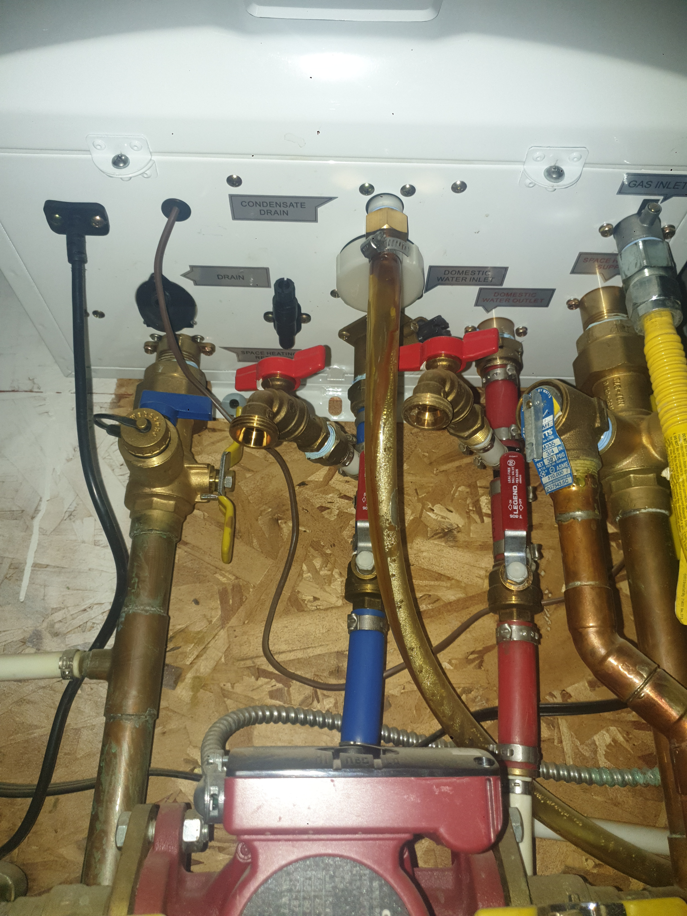
I may have to repipe this stuff, which is ok. It works, but it's not done how I'd like.
The water lines are getting redone, needs to be 3/4" at least (they used 1/2") and water softener and filters. Just waiting on redoing a bathroom which involves moving some walls, eliminating a closet, etc...
 0
0 -
Seems to be working now I think.
 0
0 -
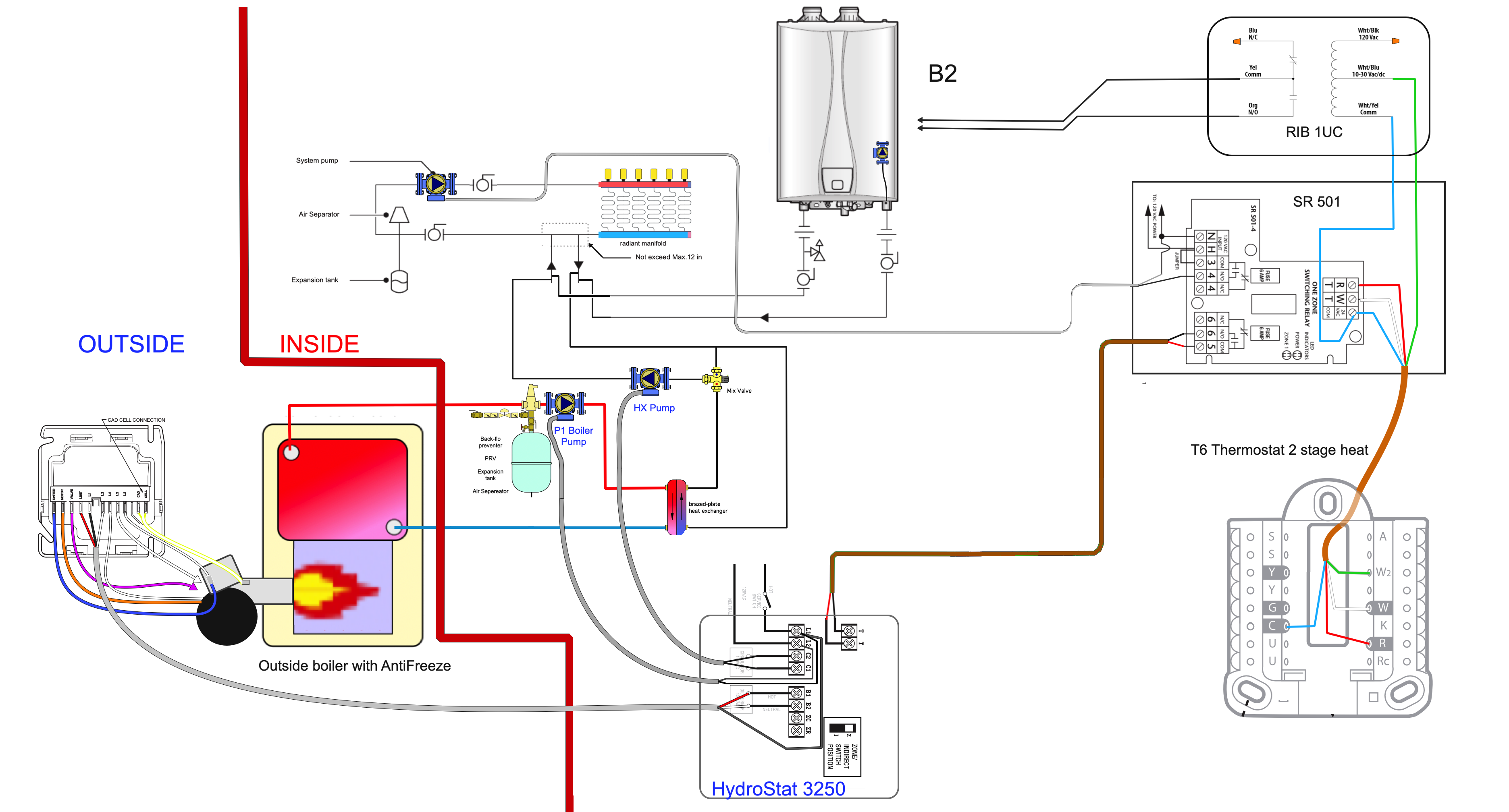
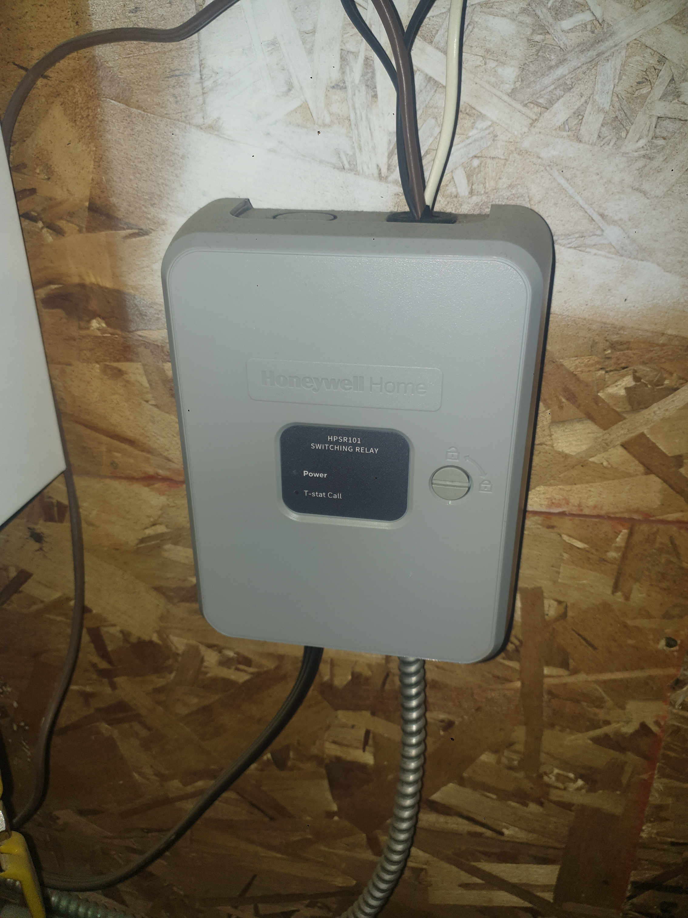
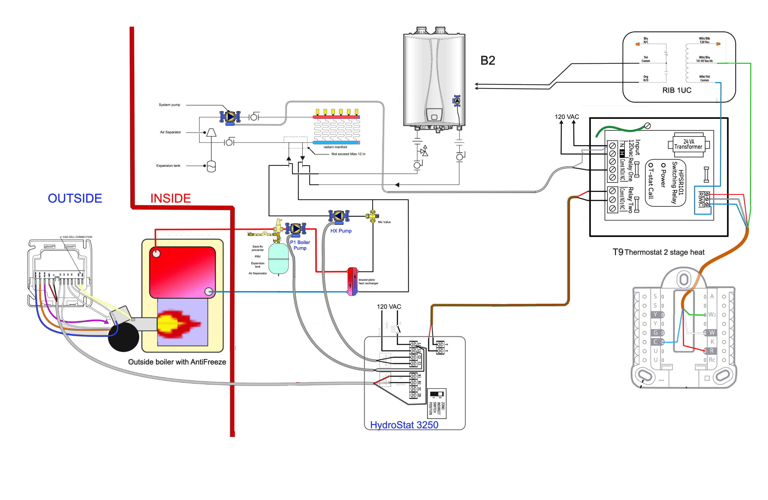
This is the diagram you need to use. There is one set of thermostat wires that I do not know where they go to on the Vesta VRC 120. But it is easy to tell you what to do. There is a two conductor low voltage wire that comes from the Honeywell HPSR 101 that connects to the Vesta VCR120. That wire should be connected to the Com and NO on Relay Two of the HPSR 101. You will remove them and connect Com and NO on Relay Two of the HPSR 101to the HydroStat 3250 T T terminals as shown
The wires you remove from Com and NO on Relay Two of the HPSR 101 will be connected to the Com and NO wires on the RIB U1C as shown below. The RIB U1C will be powered by W2 terminal of the T9 thermostat as shown by the green wire on the diagram connected to 10 to 30 VAC on the RIB U1C . The COM wire will be connected to the HPSR 101 transformer as shown by the blue wire on the diagram.
This diagram should be printed and placed with the both boiler manuals near the Vesta boiler
Since you are using a 120 size boiler, and we do not know the heat loss of the central heat area, then you may need a larger heat exchanger. The one I specified earlier was based on an 80 size boiler. The piping may also need to be 1-1/4" because 1" can only handle up to 80,000 BTUh under normal conditions.
Once you are ready to commission the oil boiler, you will set the low limit on the HydroStat 3250 to 140° and set the High limit to at least 160°. Pay close attention to the wiring of the circulator pumps on the Oil Boiler. I have the antifreeze boiler circulator pump operating constantly whenever the oil boiler is powered to operate. The HX to System pump will only operate when there is a call for heat from the thermostat. I believe this will be the best design to keep the outdoor boiler heating water mixture constantly moving when it is cold out.
Edward Young Retired
After you make that expensive repair and you still have the same problem, What will you check next?
0 -
The Vesta is controlled off a plug marked "RCOP"
The schematic in the cover says "Option RCOP"
In the boiler the 2 brown wires coming off it have a tag labeled "zone control relay"
The remote control in the diagram is for the front display which shows the water temp
0 -
It goes T Stat to Honeywell relay control, then to the boiler. The relay also outputs a 120v line to the secondary loop circulator (the 3 speed Grunfos)
Black wires just goes to a delay in make timer that there to reduce cycle times that the T stat calls for heat. It tended to call for heat and then be satisfied only a few mins later and I got no where with Honeywell support on a fix... it's an issue I found others had too.
0 -
I can't edit, but wanted to add white wire is from T Stat, brown it too boiler. Silver BX is to the Grunfos. Black wire is 120v feed plugged into an outlet. Boiler also plugged in on seperate cord.
0 -
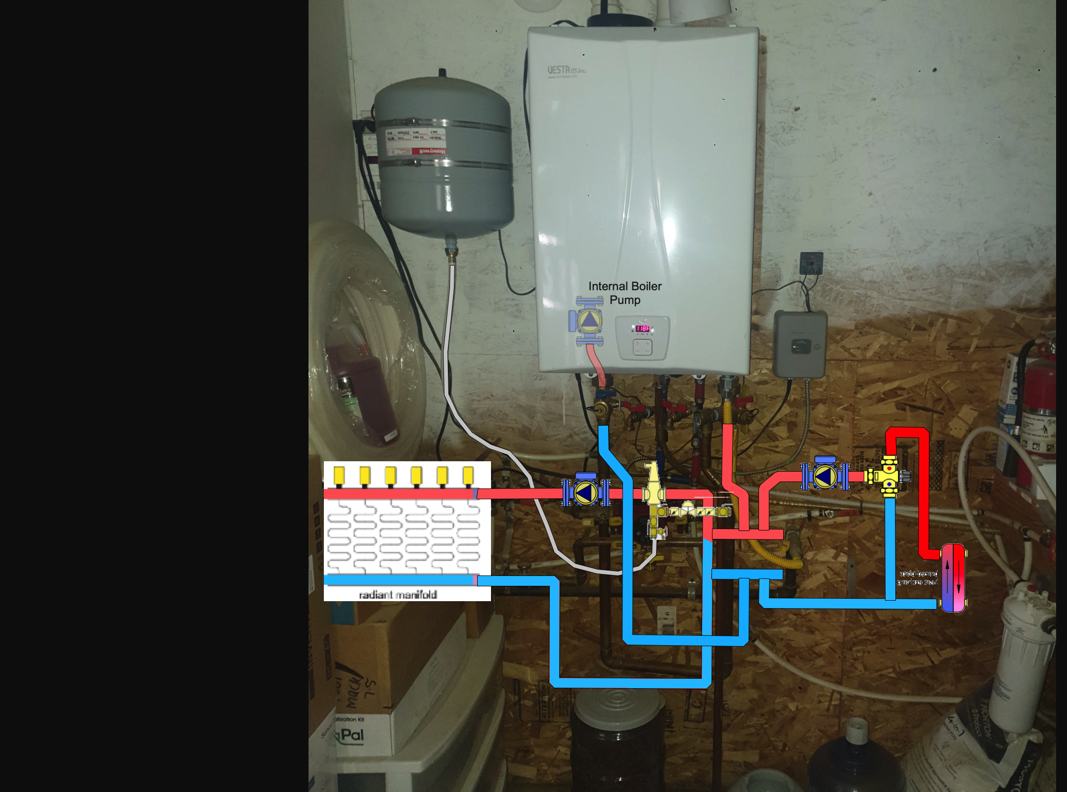
The CH piping looks fine. I have replaced the picture of the Vests boiler with the control inside the boiler. I had a feeling that the (Option) RCOP jumper in the diagram was the thermostat location, but I needed you the confirm this. The Honeywell HPSR101 relay two C and NO terminals are connected to RCOP on the Vesta.
When you are ready to do the control wiring you will purchase the RIB U1C relay and connect the C and NO from the RIB U1C relay to the RCOP on the Vesta VRC120. as shown in this diagram.
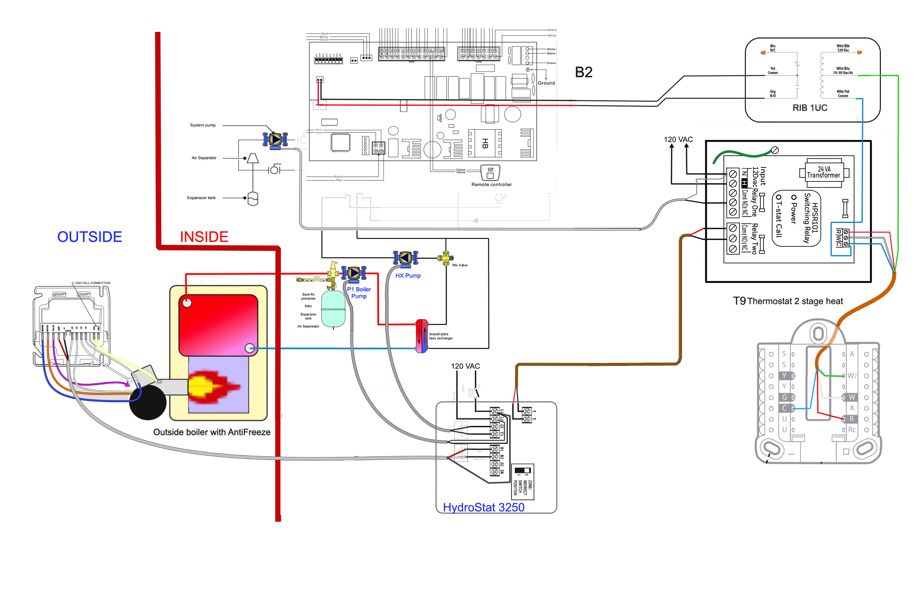
That will leave the HPSR101 relay two C and NO terminals availabe to operate the oil boiler as the primary heat source. If the Oil Boiler system fails to maintain the desired set point temperature, then the Stage 2 of the thermostat will operate the RIB U1C relay and the Vesta VRC 120 will operate to maintain the necessary heat for the building.
If any of this information is unclear please Private Message (PM) me and I will be happy to go over all the details and the control logic, sequence of operation and how to connect all the wires.
You will want to print this diagram and keep it with your boiler room manuals for both boilers and other documents.
Edward Young Retired
After you make that expensive repair and you still have the same problem, What will you check next?
0 -
In this diagram your boiler is properly connected using primary secondary piping. Not exactly like the book, but acceptable. Your boiler is on the primary loop because the expansion tank is connected to that loop. The central heat system is on the secondary loop. Nothing wrong with that setup.
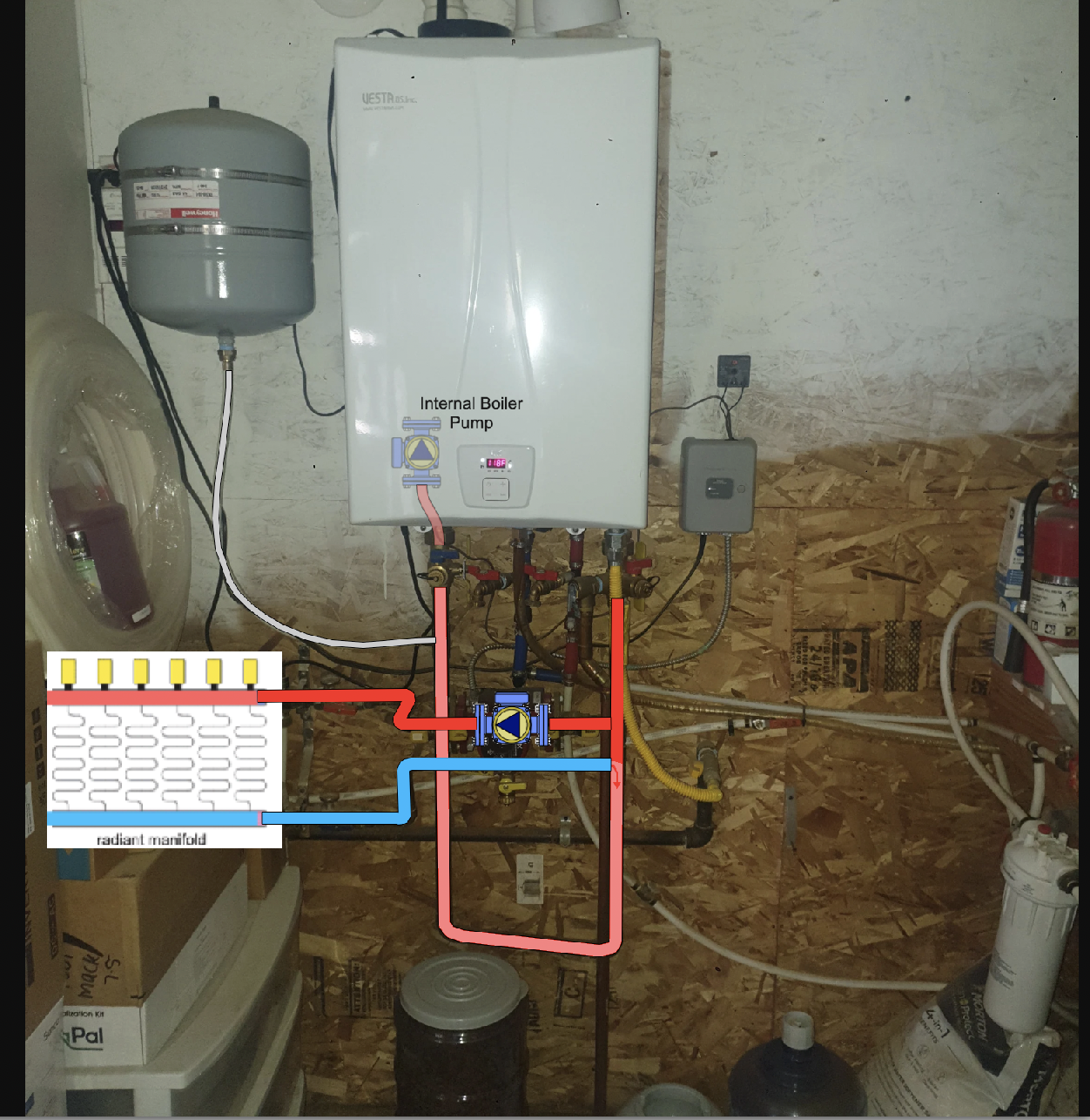
Thwe problem comes in when you want to add a second boiler that has its own circulator pump. You can just put it anywhere, because you don't want the pumps working against each other looking for the point of no pressure change, namely the expansion tank. It needs to be in the same place for both boilers to be able to use it equally, so a repipe may be in order.
According to the Vesta Manual the proper piping is to use the Central Heat (CH)Vsystem as the primary loop and add the boiler to that loop as a secondary loop, like this. I have replaced the radiators in the factory drqwing with your radiant heat manifold and loops See haw the expansion tank is connected to the CH loop?
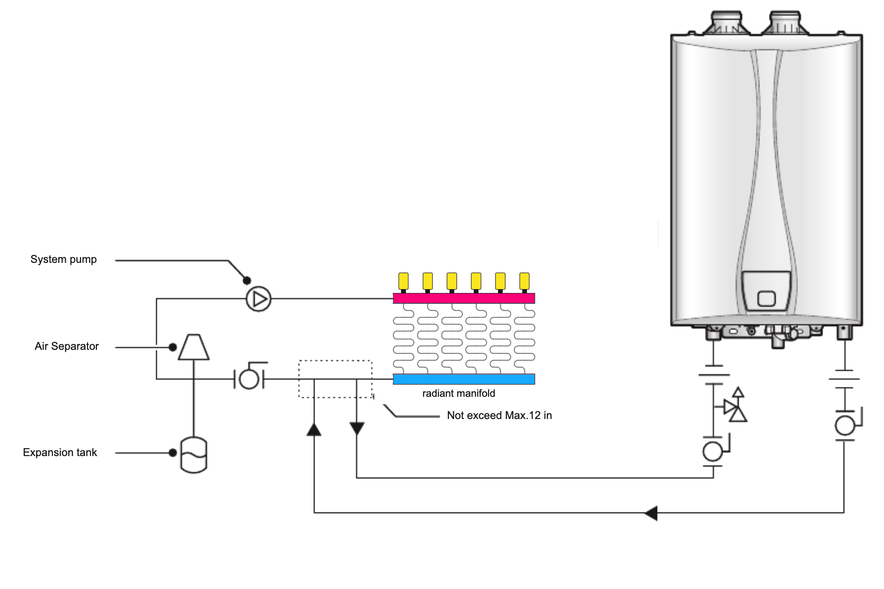
When it is time to add another boiler, you can just manifold it into the secondary branch loops like this:
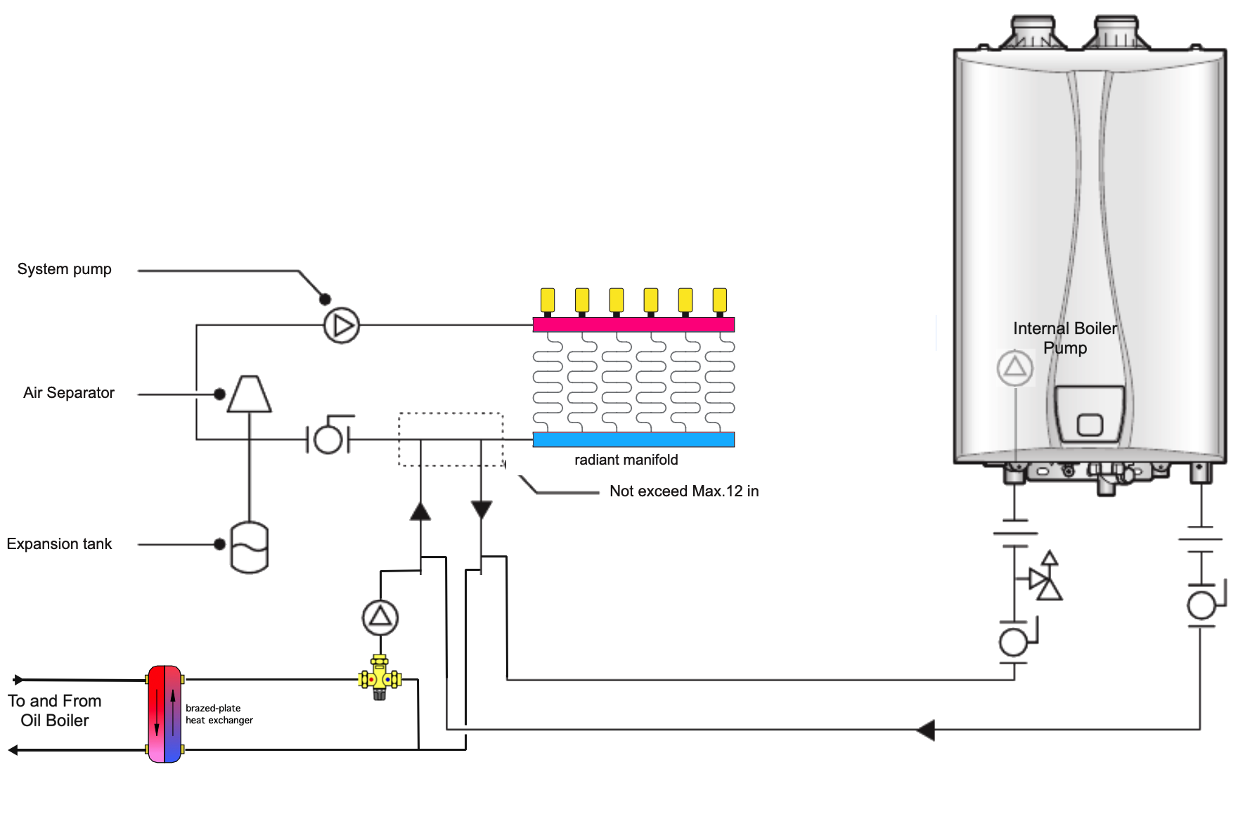
You can see the expansion tank is in the same place relative to both heat sources. The heat exchanger (HX) from the oil boiler's pump in pumping into primary loop and the internal pump in the boiler is pumping into the primary loop by way of the same closely spaced tees, and both see the expansion tank equally. Here is how I might do this with your existing setup.
It looks close for 1-1/4" copper, but that is what you need if you are moving more than 80,000 BTUh out of that boiler, and the oil system HX into your radiant floor heat. Hope this helps.
Edward Young Retired
After you make that expensive repair and you still have the same problem, What will you check next?
0 -
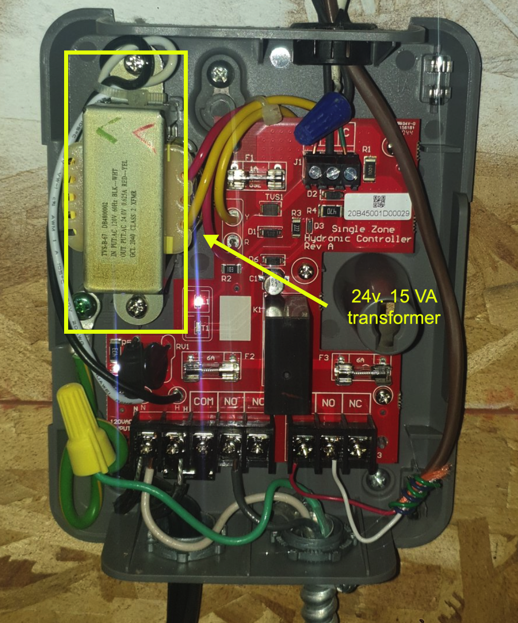
One final note. this transformer is rated at 24v. 15 VA and may not be strong enough for the Honeywell thermostat, the Honeywell HPSR101 relay and the RIB U1C relay. If that happens you can purchase a 20 VA transformer that will fit in that same position. Amana 24v. 20VA Transformer from SupplyHouse.com. I think you should be fine, but if the transformer fails after a few months of use, get the stronger transformer.
Edward Young Retired
After you make that expensive repair and you still have the same problem, What will you check next?
1 -
It's 1"
0 -
You can try it with 1" but you may need to increase if you need more than 80,000 BTUh to heat your home. That 1" or 1-1/4" is not written on stone tablets that were delivered to a mountain in a desert.
The pipe sizing is based on keeping the flow speed below 6 feet per second in order to keep the velocity noise below a noticeable level. Above 6 feet per second will become loud enough to hear. It is not that bothersome when water moves faster than that 10 FPS when you open a faucet because the noise stops when you close the tap. With a heating system that noise would be unacceptable. The next thing is the amount of gallons per minute will flow thru the pipe and this is directly related to the FPS number. And finally the temperature drop (∆T Delta T) of that water flowing thru the boiler or the radiator as the amount of heat that is added or removed from the water. With the industry standard of one gallon per minute for every 10,000 BTU based on a 20° temperature change (∆T), we can come up with some rules of thumb for pipe sizing based on the amount of heat you need to transfer.
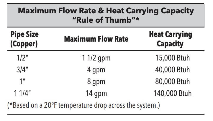
If you change the flow rate or the ∆T, you can also adjust the pipe size. So it is possible that 1” can be made to work for you by FPS or GPM, or by changing the ∆T in order to get the system to work.
For example you can get 100,000 BTU to go through 1” pipe if there is a 25° ∆T in the design. But when the water gets to the emitters (the radiant floor for example) it must move slower in order to release more heat to the floor. The longer the water stays in the emitter the more heat it will release. You also need to let the water stay in the boiler longer in order to change the ∆T in the boiler. So slowing down the water may be able to move more BTU through the smaller pipe.
The best person to make those calculations would be hot_rod if he is interested, since he does that stuff all the time, and I have stopped designing systems since I retired and might make mistakes and don't want you to rely on my numbers where dollars and cents are involved. But It may work with 1” with the proper flow and ∆T. It may also be just fine if you only need 80,000 BTUh on the coldest days. Without a proper load calculation, we may be discussing a point that does not really matter.
Edward Young Retired
After you make that expensive repair and you still have the same problem, What will you check next?
1 -
I'm not sure the reason for sizing the boiler to 120k BTU or the 1". I'd guess more that it was more common.
The boiler at my old place used 1.25" and it was a pain when I repiped some of it. I had to get the copper pipe and fittings at a plumbing supply 30 miles away as all the hardware store only carry up to 1"
0 -
This Heat exchanger suitable?
0 -
Well ordered it, so hopefully it's ok.
0 -
Saw a video of a setup a guy did with a wood boiler and he simply had an aquastat at the wood boiler feed.
T Stat in house kicks on and kicks on circulators. If the water temp is under whatever the aquastat is set to, it allows the secondary boiler to fire.
So used oil boiler is staying 160-180*. Aquastat set to, I dunno, 140* let's say. The Vesta wouldn't fire unless the used oil boiler wasn't making heat, or it can't keep up.
Put aquastat on the piping entering from outside, before the heat exchanger, and a delay on make timer so it would give a bit for the circulator to get going and warm the line and heat exchanger.
That make any sense or using the 2 stage T Stage like discussed a bit ago the a better way?
0

Categories
- All Categories
- 87.6K THE MAIN WALL
- 3.3K A-C, Heat Pumps & Refrigeration
- 59 Biomass
- 429 Carbon Monoxide Awareness
- 124 Chimneys & Flues
- 2.2K Domestic Hot Water
- 5.9K Gas Heating
- 119 Geothermal
- 168 Indoor-Air Quality
- 3.8K Oil Heating
- 78 Pipe Deterioration
- 1K Plumbing
- 6.6K Radiant Heating
- 394 Solar
- 16K Strictly Steam
- 3.5K Thermostats and Controls
- 56 Water Quality
- 51 Industry Classes
- 50 Job Opportunities
- 18 Recall Announcements