Help Please! Half of Hydronic Zone not heating

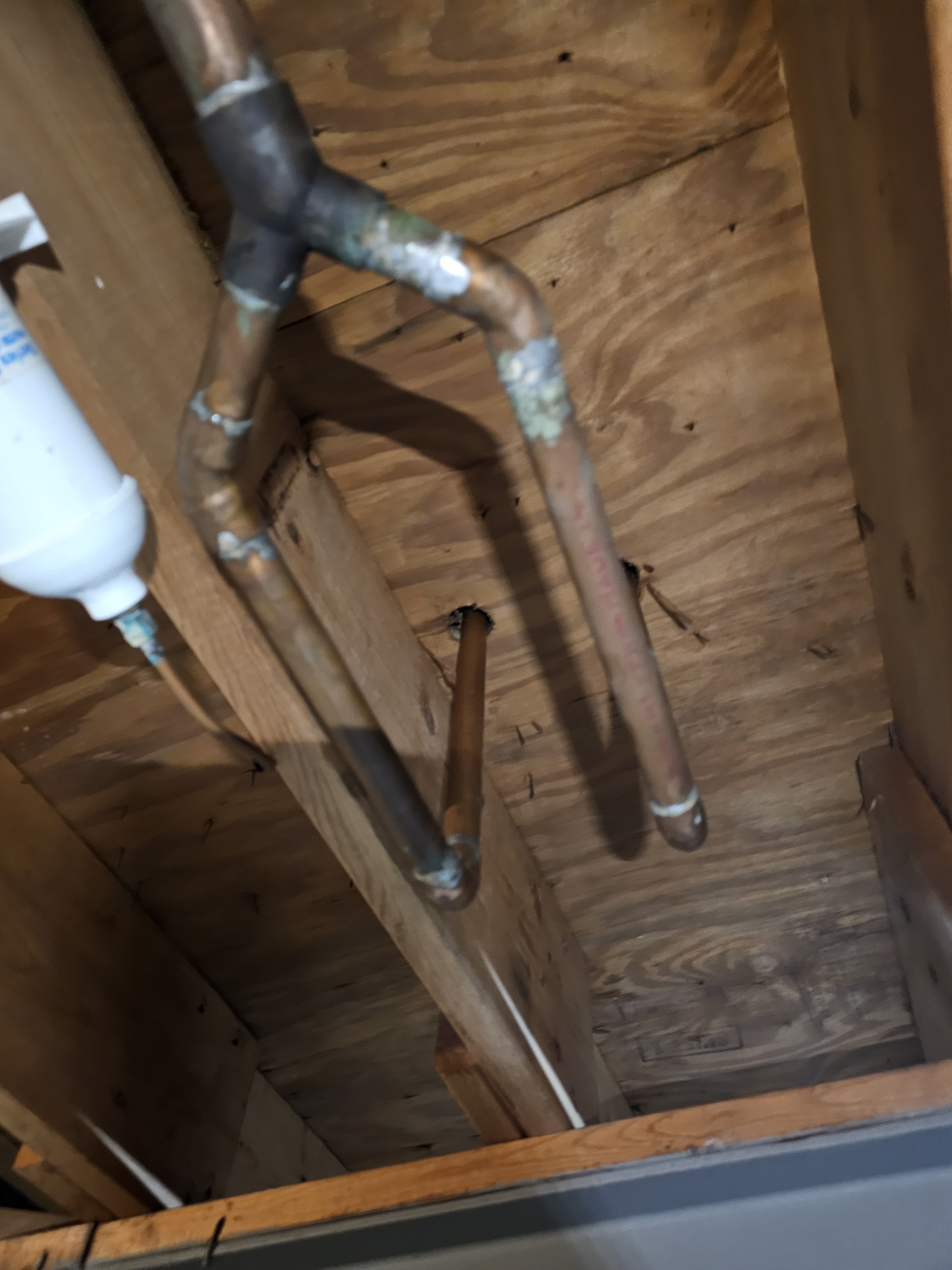
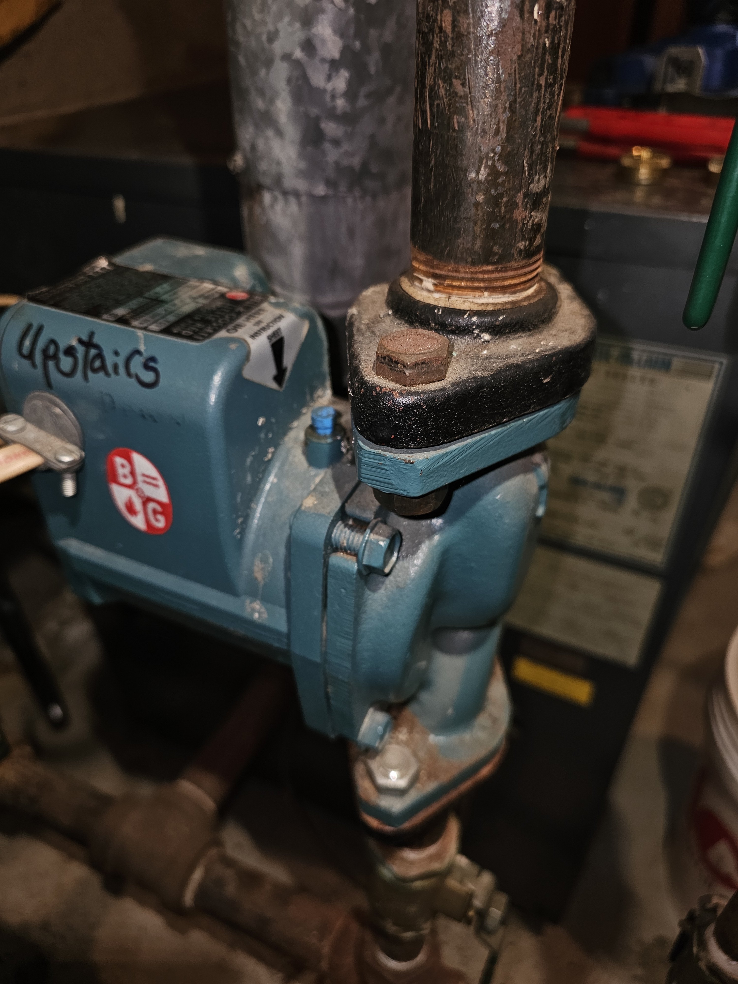
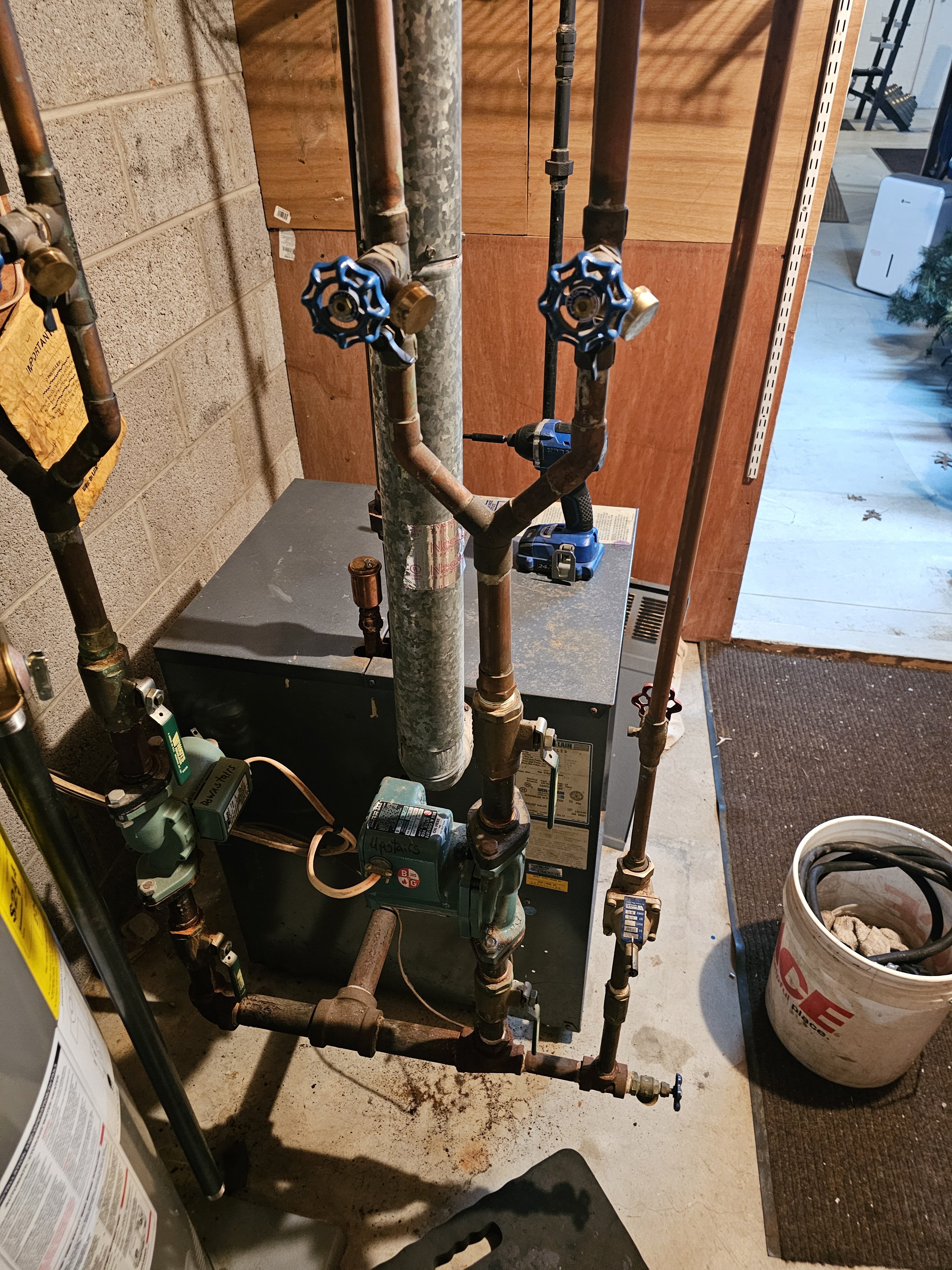
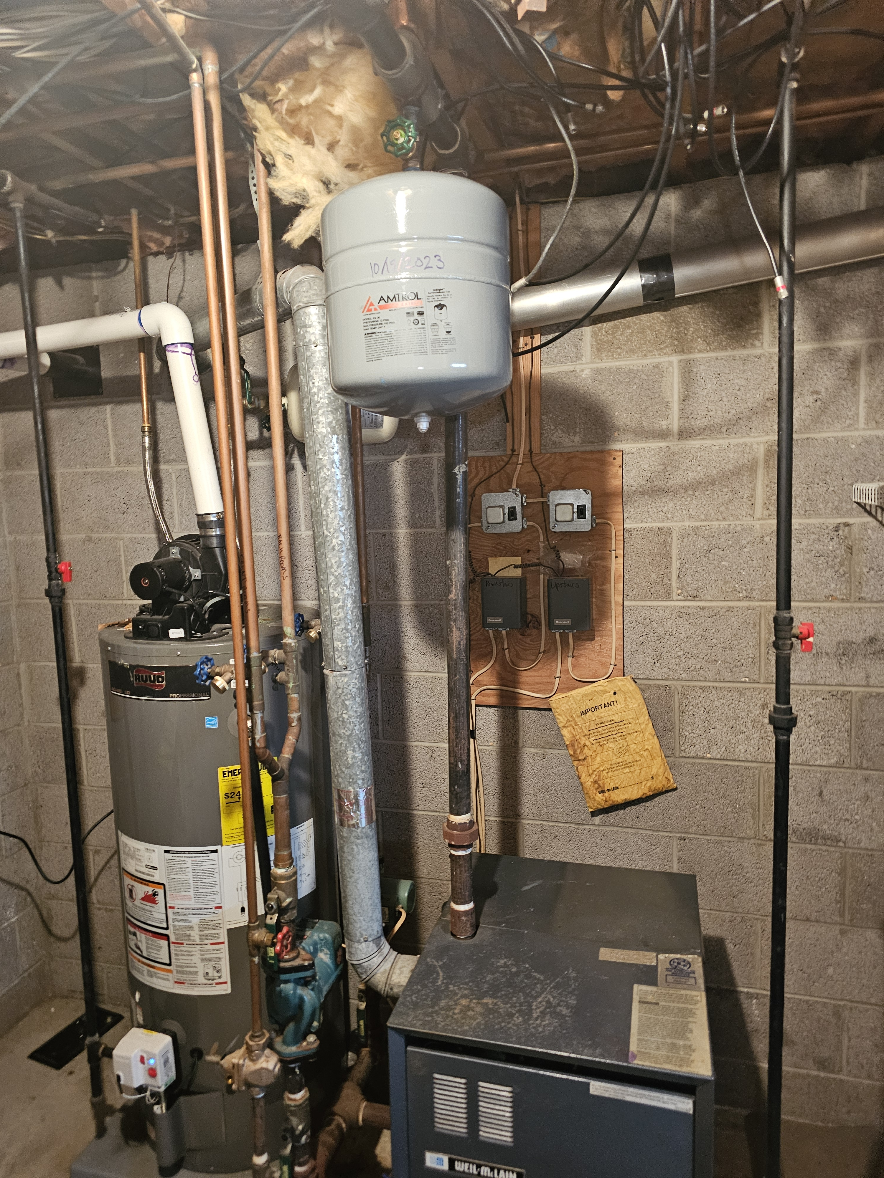
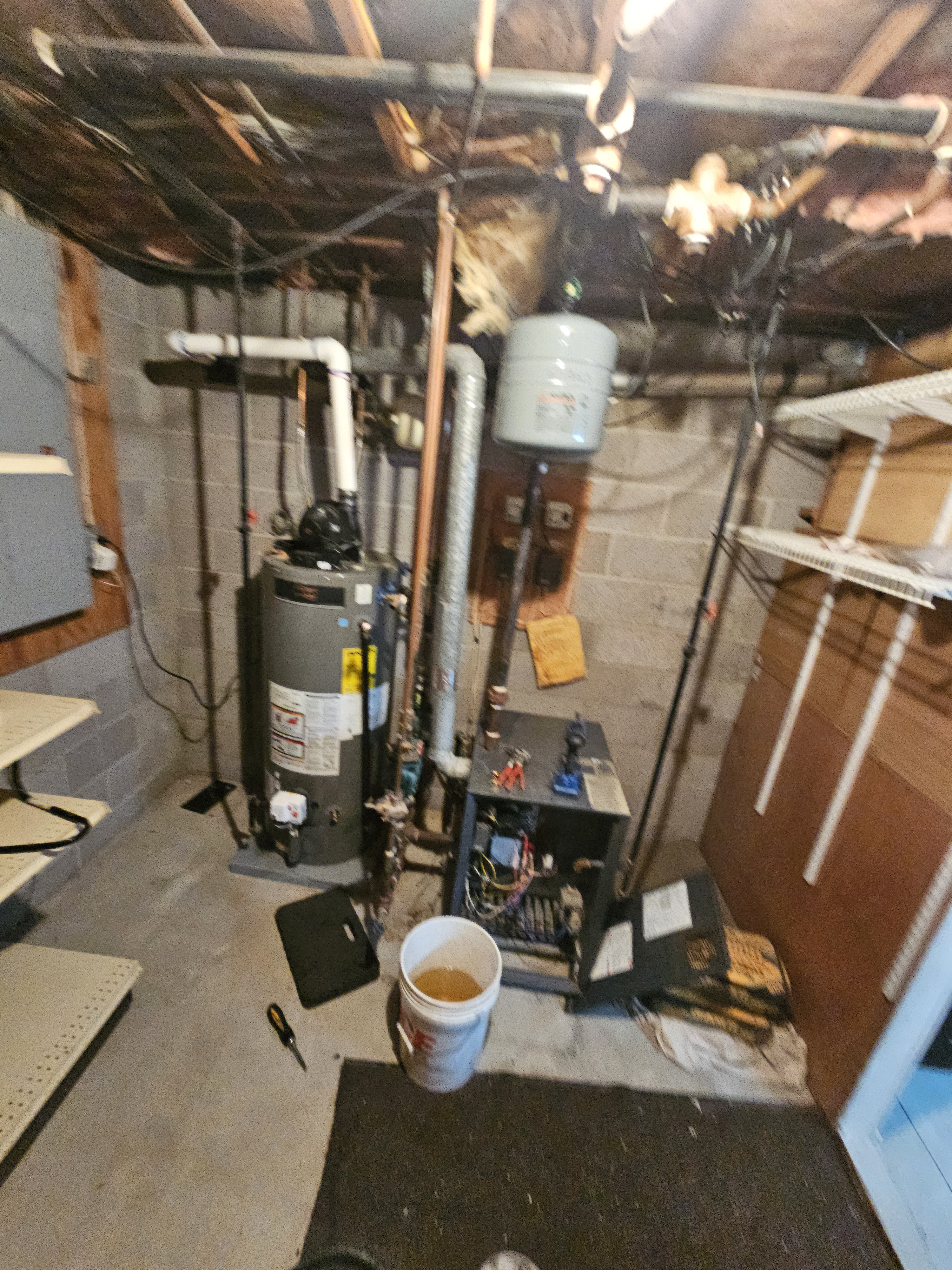
2 Circ Pumps, Each circ pump has 2 pipes branching into a Y before it. Both pumps on Return. Downstairs zone is fine. Upstairs zone, only half of the upstairs gets warm. And the half that gets warm, gets HOT. Basically only one of the 2 pipes going to that circ pump gets hot. I tried using the balancing valve on it, tried purging the system. There's definitely water in both pipes. Circ pump seems to be working. However, I noticed when I turn the balancing valve on the side that's working, I'll hear a noticeable difference in waterflow. However, when I turn the balancer on the side that's not working, it is completely silent.
I've tried everything I know how to do.
New expansion tank, new air eliminators, pressure & water temp are good.
I'm suspecting either a clogged zone, or the pump isn't powerful enough.
All help is appreciated! See pics attached.
Comments
-
To your knowledge, has it ever worked?1
-
if you close the working balancing valve, you get no flow thru the not working side?
and you tried purging with the same valve closed? (the working side closed?)
did you also close the blue circ ball vale below the 2 balancing valves? blue needs to be closed to purgeknown to beat dead horses1 -
Pretty sure they said it did. Will confirm asap.DCContrarian said:To your knowledge, has it ever worked?
0 -
Yes, I did all that.neilc said:if you close the working balancing valve, you get no flow thru the not working side?
and you tried purging with the same valve closed? (the working side closed?)
did you also close the blue circ ball vale below the 2 balancing valves? blue needs to be closed to purge
And when I do purge like that, the non-working side will get warm and blow out warm water.
However, it only gets warm basically up to the ceiling and maybe a foot or so back. The rest of the pipes on that side stay cool...0 -
Are you using the fast fill position on the fill valve when you purge? With that large steel piping you'll need a good flow rate to get a good purge. Keeping the boiler gauge at 20- 25 psi as you purge may help.Bob "hot rod" Rohr
trainer for Caleffi NA
Living the hydronic dream1 -
Yep. Tried doing that.hot_rod said:Are you using the fast fill position on the fill valve when you purge? With that large steel piping you'll need a good flow rate to get a good purge. Keeping the boiler gauge at 20- 25 psi as you purge may help.
It comes out both pipes pretty solid...0 -
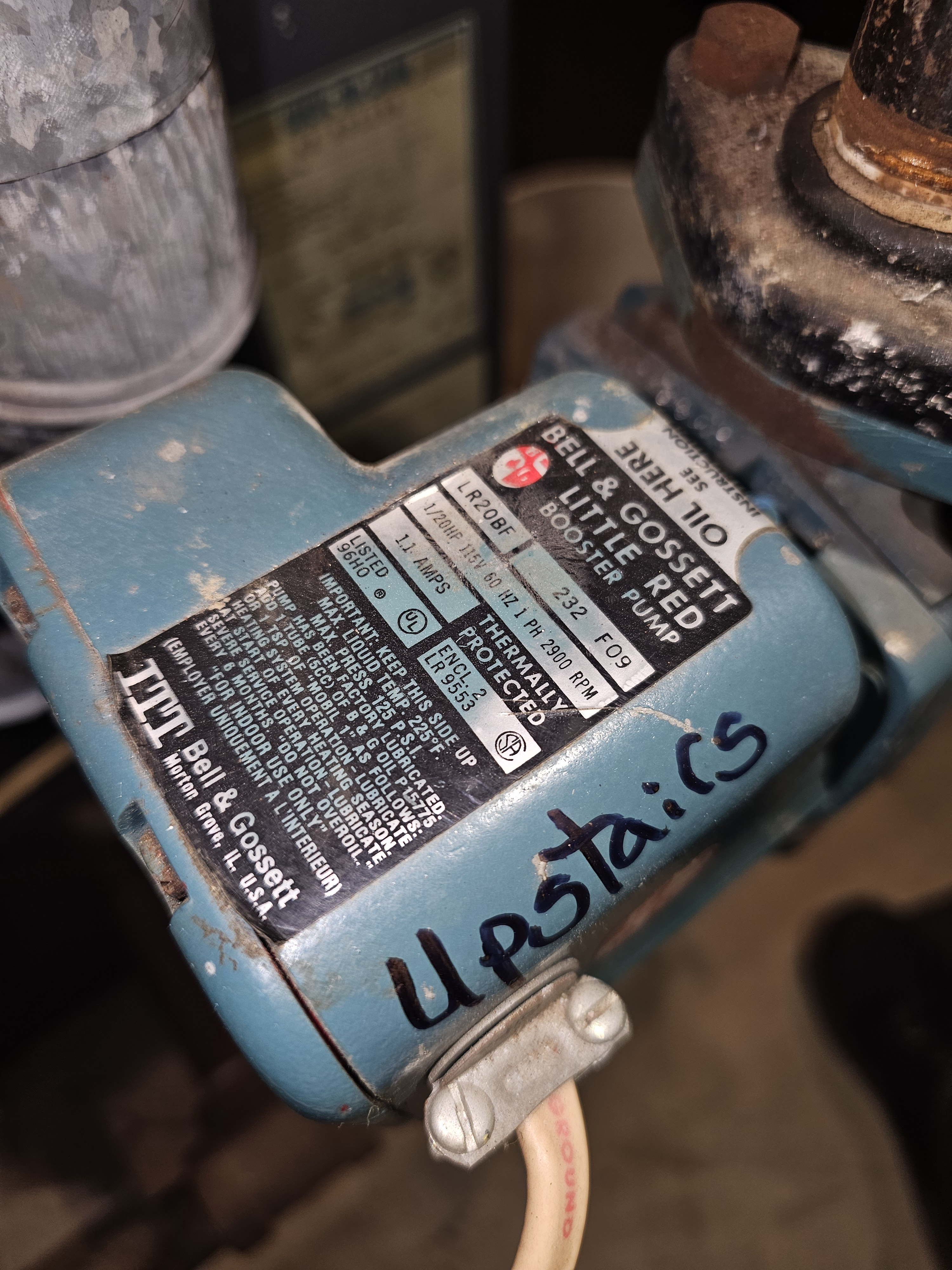
Are you purging all 4 loops? This may sound ridiculous, but the magic marker on the B&G circ looks fairly new, did they maybe mark the wrong circle for the second floor? I’ve seen this happen so many times, if everything is purged properly, try closing down the butterfly valve on the working side, see if the circ is pushing water through the cold side, it is possible that the B&G circ is toasted and is heating by gravity. That’s where I’d start1
-
Yes tried purging all 4 loops. 3 out of 4 working fine. Definitely labelled correctly. Butterfly valve is the Balancing valve right? It's difficult to close and I still hear water spraying by. Cold side still stays cold.StevieG420 said:Are you purging all 4 loops? This may sound ridiculous, but the magic marker on the B&G circ looks fairly new, did they maybe mark the wrong circle for the second floor? I’ve seen this happen so many times, if everything is purged properly, try closing down the butterfly valve on the working side, see if the circ is pushing water through the cold side, it is possible that the B&G circ is toasted and is heating by gravity. That’s where I’d start
I thought the same thing about the circ pump. How would I confirm that theory?0 -
It's almost certainly airlocked and will need to be power purged through that problem loop only. The circ itself will not provide adequate flow for this- it'll need to be done via an external pump or domestic water pressure. Completely isolate the 3 working loops and only purge the problem loop by itself.
 2
2 -
Okay the only ways to isolate are the ballvalve for each zone above circ pump, and the balancing valves which are very difficult to completely close.GroundUp said:It's almost certainly airlocked and will need to be power purged through that problem loop only. The circ itself will not provide adequate flow for this- it'll need to be done via an external pump or domestic water pressure. Completely isolate the 3 working loops and only purge the problem loop by itself.
I'm thinking of closing all the valves maybe hooking up a transfer pump to purge opening on the problem loop, and opening the fill valve manually.
I'm considering grabbing either a cheap pump 1/10hp or going for the 1/4 Milwaukee.
I honestly don't use them alot.
Do you it'll work using a 1/10HP?
Also, what if this doesn't work, What should I try next?0 -
If you have a water heater near by, connect a short garden hose, flush for a few minutes and then connect that to the boiler for a good power purge. You need to keep an eye on the pressure however, over 30 psi and you'll trip the relief valve. Hopefully it trips at 30 psi.
Any hose bib works even an outdoor bib, to connect to.Bob "hot rod" Rohr
trainer for Caleffi NA
Living the hydronic dream2 -
Get a water pressure gauge with a garden hose thread, you can get it at Home Depot. First, put it on the drain at the bottom of the boiler and open the valve, that tells you what the baseline pressure in the boiler is. Then put it on one of the drains that are right above the circulator. That should be noticeably less than the baseline when the circulator is running (I'm assuming that circulator is on the return and pumping down so the drains are on the suction side). If you cut the power the pressure should jump right back to baseline.Hot_n_Cold said:
Yes tried purging all 4 loops. 3 out of 4 working fine. Definitely labelled correctly. Butterfly valve is the Balancing valve right? It's difficult to close and I still hear water spraying by. Cold side still stays cold.
I thought the same thing about the circ pump. How would I confirm that theory?
1 -


Tried doing this. Boiler pressure is about 20psiDCContrarian said:
Get a water pressure gauge with a garden hose thread, you can get it at Home Depot. First, put it on the drain at the bottom of the boiler and open the valve, that tells you what the baseline pressure in the boiler is. Then put it on one of the drains that are right above the circulator. That should be noticeably less than the baseline when the circulator is running (I'm assuming that circulator is on the return and pumping down so the drains are on the suction side). If you cut the power the pressure should jump right back to baseline.Hot_n_Cold said:
Yes tried purging all 4 loops. 3 out of 4 working fine. Definitely labelled correctly. Butterfly valve is the Balancing valve right? It's difficult to close and I still hear water spraying by. Cold side still stays cold.
I thought the same thing about the circ pump. How would I confirm that theory?
On the loop that's working, I can adjust the balancing valve to fluctuate between approx 15psi-20psi.
On the loop that's not working, I cannot adjust the pressure using the balancing valve at all. It stays at
approx 16psi no matter what. Also, even if I adjust the other balancing valve. It doesn't change the other loop's pressure.
Guy at parts desk said I may need to replace the balancing valves completely.
Also, I'm very confident I got a good purge through the lines. I'm getting good flow through even the non-working valve.
Is it possible that'll fix it?
0 -
Pressure Relief definitely works! lolhot_rod said:If you have a water heater near by, connect a short garden hose, flush for a few minutes and then connect that to the boiler for a good power purge. You need to keep an eye on the pressure however, over 30 psi and you'll trip the relief valve. Hopefully it trips at 30 psi.
Any hose bib works even an outdoor bib, to connect to.0 -
Hot_n_Cold said:
Tried doing this. Boiler pressure is about 20psiDCContrarian said:
Get a water pressure gauge with a garden hose thread, you can get it at Home Depot. First, put it on the drain at the bottom of the boiler and open the valve, that tells you what the baseline pressure in the boiler is. Then put it on one of the drains that are right above the circulator. That should be noticeably less than the baseline when the circulator is running (I'm assuming that circulator is on the return and pumping down so the drains are on the suction side). If you cut the power the pressure should jump right back to baseline.Hot_n_Cold said:
Yes tried purging all 4 loops. 3 out of 4 working fine. Definitely labelled correctly. Butterfly valve is the Balancing valve right? It's difficult to close and I still hear water spraying by. Cold side still stays cold.
I thought the same thing about the circ pump. How would I confirm that theory?
On the loop that's working, I can adjust the balancing valve to fluctuate between approx 15psi-20psi.
On the loop that's not working, I cannot adjust the pressure using the balancing valve at all. It stays at
approx 16psi no matter what. Also, even if I adjust the other balancing valve. It doesn't change the other loop's pressure.
Guy at parts desk said I may need to replace the balancing valves completely.
Also, I'm very confident I got a good purge through the lines. I'm getting good flow through even the non-working valve.
Is it possible that'll fix it?
What is the vertical distance between the boiler drain and the spot where you tested?
When you cut the power, does the pressure on the loop that's not working change?
With zero flow you'd expect the non-working loop to be at boiler pressure. That's what I'm trying to reconcile.1 -
Probably 3 feet vert distance.
What is the vertical distance between the boiler drain and the spot where you tested?
When you cut the power, does the pressure on the loop that's not working change?
With zero flow you'd expect the non-working loop to be at boiler pressure. That's what I'm trying to reconcile.
From what I remember the pressures equalize when powered off.
I'll check again tomorrow.
If pressure doesn't change when powered off... What would that allude to?
If pressure does equalize What would that mean?
0 -
I think the scale on that gauge is too wide to be of much use for measuring altitude / pressure difference or delta P added by the circ. A 30 psi gauge is a better option. But they are harder to find with the lazy/ indicator hand.Bob "hot rod" Rohr
trainer for Caleffi NA
Living the hydronic dream1 -
I'll search around for one. What Delta P should I be looking for on this pump?hot_rod said:I think the scale on that gauge is too wide to be of much use for measuring altitude / pressure difference or delta P added by the circ. A 30 psi gauge is a better option. But they are harder to find with the lazy/ indicator hand.
0 -
There are a few different “pressures” that we talk about in hydronic systems.
The static pressure. Pressure that is measures anywhere in the system with no circulators operating. If the pressure reads 12 psi at the boiler, as you connect a gauge into the system higher up in the building the pressure will read lower.
.433 psi to water one foot
To get water to the top of a 25’ building you need at least .,433 X 25 psi 10.8 psi
The next pressure is the dynamic pressure, pressure added to the system when the circulator spins. This added “head” overcomes the resistance in the piping and fittings.
You could calculate that added pressure, or with gauges in the inlet and outlet side of the circulator you could measure that.
For determine a leak, just measure the static fill after you add water then hours or the next day.
If the boiler is not operating the pressure would not increase. Increasing the temperature of the water increases the pressure a certain amount. Eliminate that by not heating the system as you troubleshoot.
If the pressure drops more than a psi or so, then you determine where it is going to. Pressure that continues to drop usually indicates a leakBob "hot rod" Rohr
trainer for Caleffi NA
Living the hydronic dream1 -
hot_rod said:
There are a few different “pressures” that we talk about in hydronic systems.
The static pressure. Pressure that is measures anywhere in the system with no circulators operating. If the pressure reads 12 psi at the boiler, as you connect a gauge into the system higher up in the building the pressure will read lower.
.433 psi to water one foot
To get water to the top of a 25’ building you need at least .,433 X 25 psi 10.8 psi
The next pressure is the dynamic pressure, pressure added to the system when the circulator spins. This added “head” overcomes the resistance in the piping and fittings.
You could calculate that added pressure, or with gauges in the inlet and outlet side of the circulator you could measure that.
For determine a leak, just measure the static fill after you add water then hours or the next day.
If the boiler is not operating the pressure would not increase. Increasing the temperature of the water increases the pressure a certain amount. Eliminate that by not heating the system as you troubleshoot.
If the pressure drops more than a psi or so, then you determine where it is going to. Pressure that continues to drop usually indicates a leak
Make sure the makeup water valve is off when checking for leaks.1 -
Probably 3 feet vert distance.Hot_n_Cold said:
What is the vertical distance between the boiler drain and the spot where you tested?
When you cut the power, does the pressure on the loop that's not working change?
With zero flow you'd expect the non-working loop to be at boiler pressure. That's what I'm trying to reconcile.
From what I remember the pressures equalize when powered off.
I'll check again tomorrow.
If pressure doesn't change when powered off... What would that allude to?
If pressure does equalize What would that mean?
In an earlier post you had wondered if the circulator was working. If the circulator is working, you would expect while it's running the pressure would be higher on the outlet side and lower on the inlet side. When it's off you'd expect them to be the same.
The boiler drain is very close to the outlet of the circulator so it's a reasonable substitute measurement.
With a loop that is working, what I would expect is that when the circulator is running the pressure upstream of the circulator would be somewhat lower. When the balancing valve is closed the pressure rises. That's what we're seeing on the loop that's good.
Now, correct me if I'm wrong, but what we're seeing with the loop that isn't working is:
* Pressure is lower upstream of the circulator
* Closing the balancing valve on that loop has no effect
* Closing the balancing valve on the adjacent loop has no effect
* No flow through the loop
If the loop were blocked or capped, closing the adjacent valve would cause the pressure to rise, there'd be zero flow through the circulator.
It could well be that the balancing valve on the suspect loop is shot, that would explain why closing it doesn't affect anything.
But the only explanation I can come up with for a pressure drop across the circulator but no flow is air in the pipes.1 -
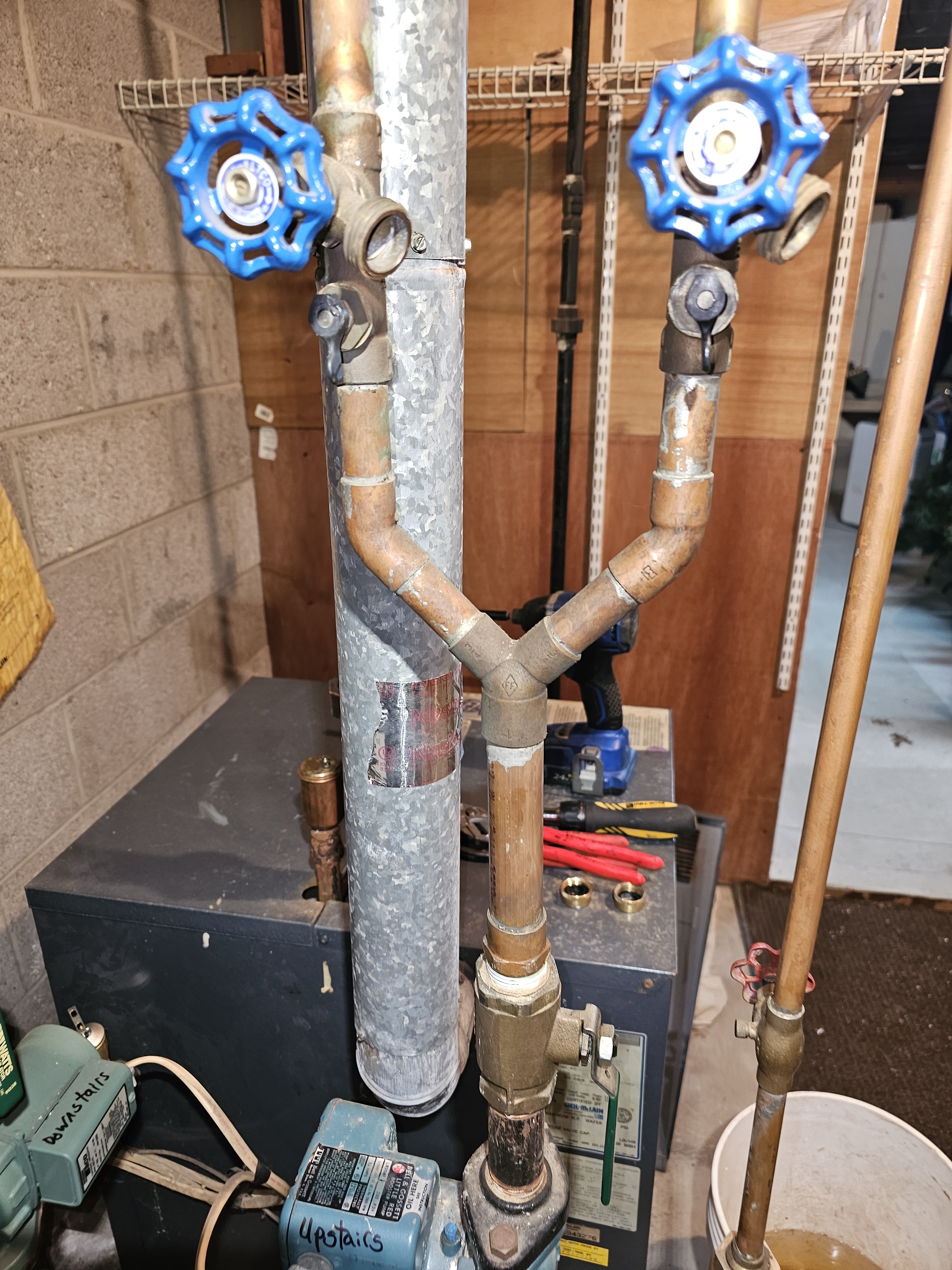
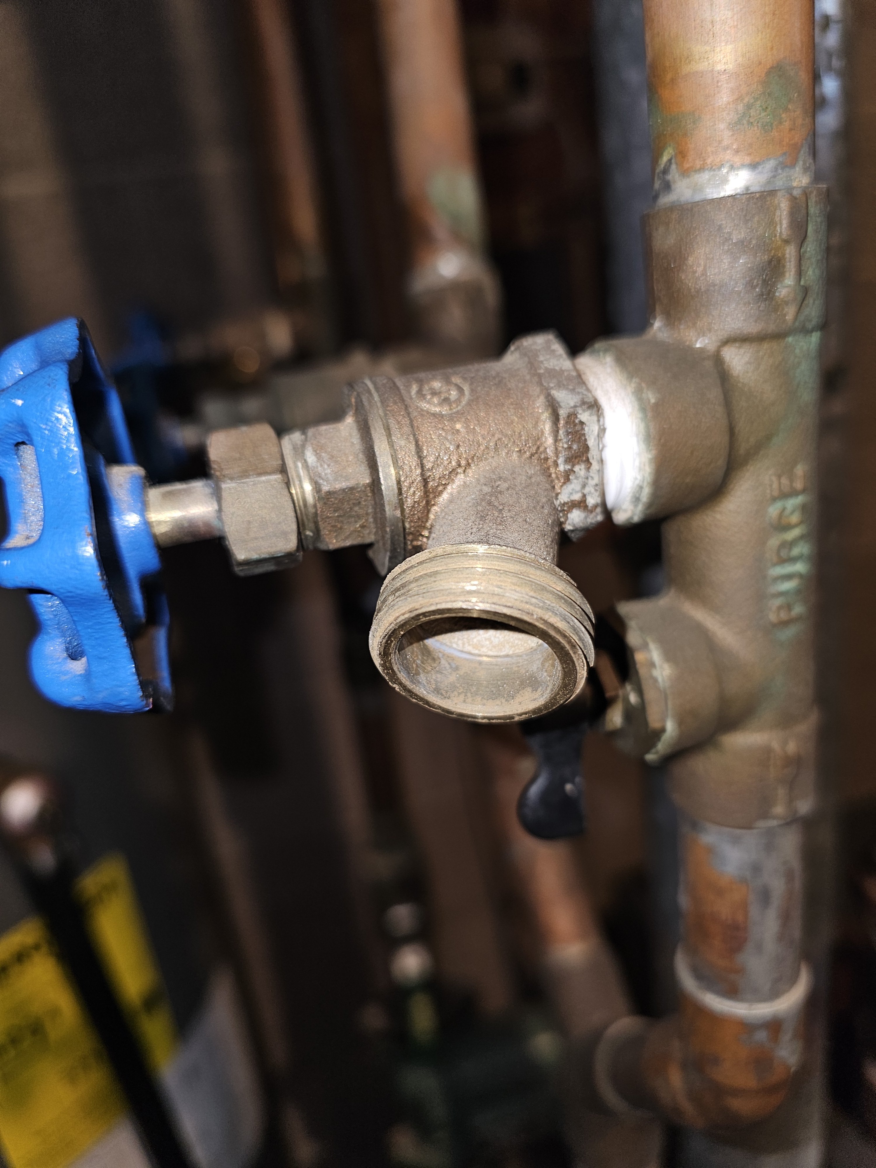
Are your balancing valves upstream or downstream of the drains on each loop? If they're downstream, you can shut off the suspect zone, open the zone valve, put a hose on the drain, put the hose in a bucket of water, and open the drain and check for flow. The system pressure should be enough to drive water through the loop and into the bucket. If the makeup water is on it should flow continuously. By putting the hose in a bucket you can see if air comes out.
In order for this to work you have to make sure the balancing valve* is working.
*(From the picture I think it's more of an isolation valve than a balancing valve. Quarter turn ball valve? Isolation).1 -
If you get a solid stream while purging I would narrow down to a flow check not holding or a circ not moving flow. You have isolation valves, so remove the 4 bolts holding the pump into the body. Power up the circ does it spin, is the impeller clean, in one piece?
While not quite as easy, the flow checks could also be pulled apart, confirm that they close off tightly.Bob "hot rod" Rohr
trainer for Caleffi NA
Living the hydronic dream1 -
DCContrarian said:In an earlier post you had wondered if the circulator was working. If the circulator is working, you would expect while it's running the pressure would be higher on the outlet side and lower on the inlet side. When it's off you'd expect them to be the same. The boiler drain is very close to the outlet of the circulator so it's a reasonable substitute measurement. With a loop that is working, what I would expect is that when the circulator is running the pressure upstream of the circulator would be somewhat lower. When the balancing valve is closed the pressure rises. That's what we're seeing on the loop that's good. Now, correct me if I'm wrong, but what we're seeing with the loop that isn't working is: * Pressure is lower upstream of the circulator * Closing the balancing valve on that loop has no effect * Closing the balancing valve on the adjacent loop has no effect * No flow through the loop If the loop were blocked or capped, closing the adjacent valve would cause the pressure to rise, there'd be zero flow through the circulator. It could well be that the balancing valve on the suspect loop is shot, that would explain why closing it doesn't affect anything. But the only explanation I can come up with for a pressure drop across the circulator but no flow is air in the pipes.
Everything you asked for confirmation about is correct.
If that valve is shot, then there's no way I could purge that loop properly. Right?
And Idk if there's flow... it seems like there is. There is a pressure drop on that loop when circulator pump starts running...
If I remember correctly atleast...
Going back today to do more tests recommended.
Considering changing the balancing valve to a ball valve per recommendation of shop worker.0 -
People have said they're called butterfly valves. Yes, I've tried doing that. Definitely a solid stream of water coming through.DCContrarian said:Are your balancing valves upstream or downstream of the drains on each loop? If they're downstream, you can shut off the suspect zone, open the zone valve, put a hose on the drain, put the hose in a bucket of water, and open the drain and check for flow. The system pressure should be enough to drive water through the loop and into the bucket. If the makeup water is on it should flow continuously. By putting the hose in a bucket you can see if air comes out. In order for this to work you have to make sure the balancing valve* is working. *(From the picture I think it's more of an isolation valve than a balancing valve. Quarter turn ball valve? Isolation).
However, I cannot guarantee it's not making it's way around the valves and coming from the other loop...
Hence why I'm considering just putting ball valves on there so I KNOW it's isolated. That's the agenda for today.0 -
Will check all that too. I thought you're not supposed to run the pumps without water in them?hot_rod said:If you get a solid stream while purging I would narrow down to a flow check not holding or a circ not moving flow. You have isolation valves, so remove the 4 bolts holding the pump into the body. Power up the circ does it spin, is the impeller clean, in one piece? While not quite as easy, the flow checks could also be pulled apart, confirm that they close off tightly.0 -
Bingo.Hot_n_Cold said:If that valve is shot, then there's no way I could purge that loop properly. Right?
 2
2 -
That's what I'm thinking (hoping*) it is...DCContrarian said:If that valve is shot, then there's no way I could purge that loop properly. Right?
Bingo.
The valves on that loop definitely seem difficult to turn and don't seem to close properly... also, the valve on the problem loop has no effect on the water pressure on the purge that's upstream of it.
I think I got this figured out... will see...0 -
running the circ for a few seconds with it removed from the body will not damage it. It's just a quick test.
Also an example of what can happen when checks are not holding.Bob "hot rod" Rohr
trainer for Caleffi NA
Living the hydronic dream0 -
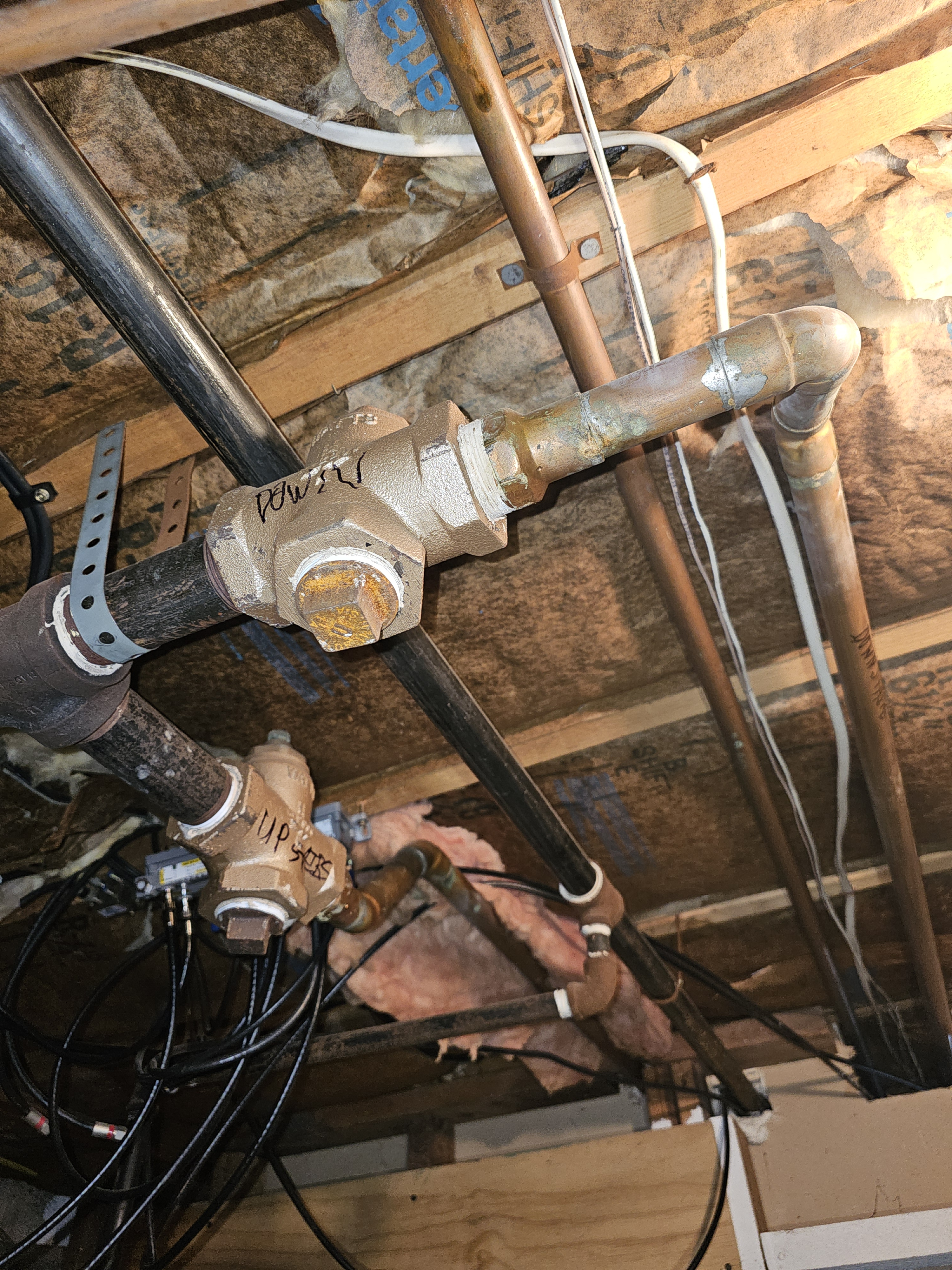
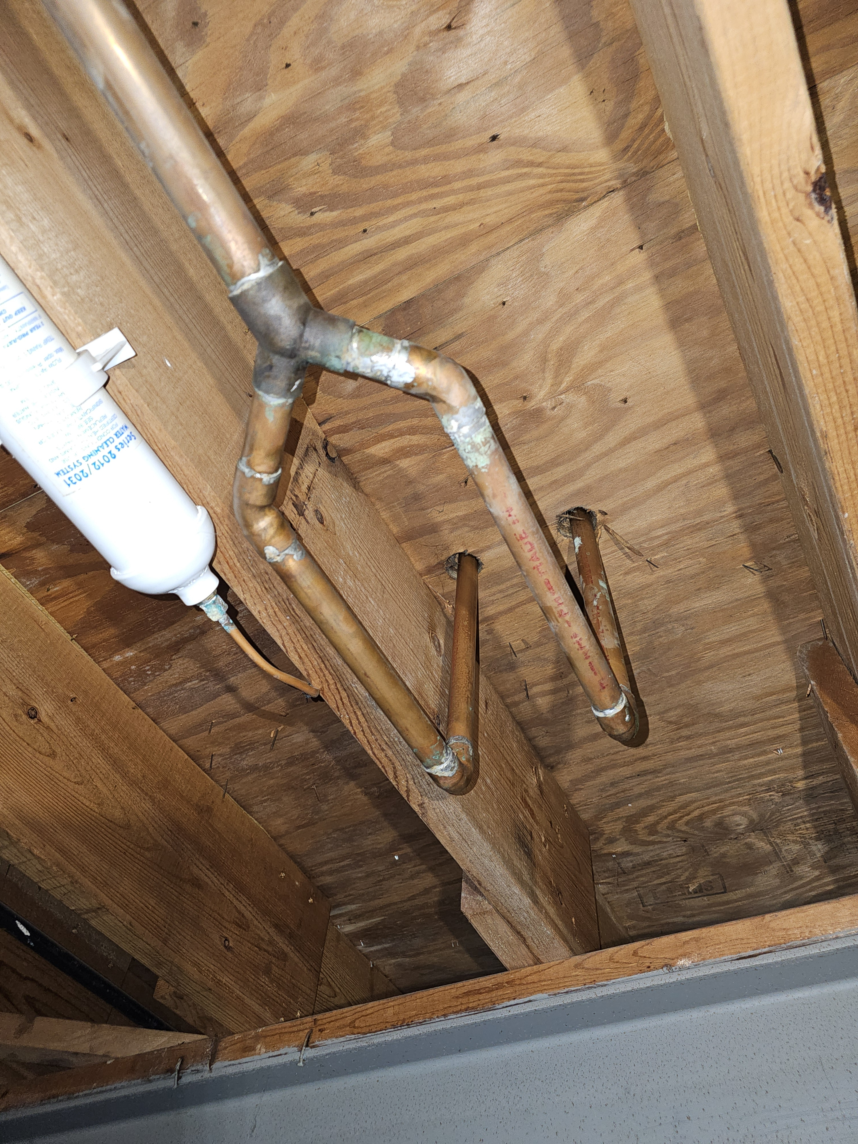
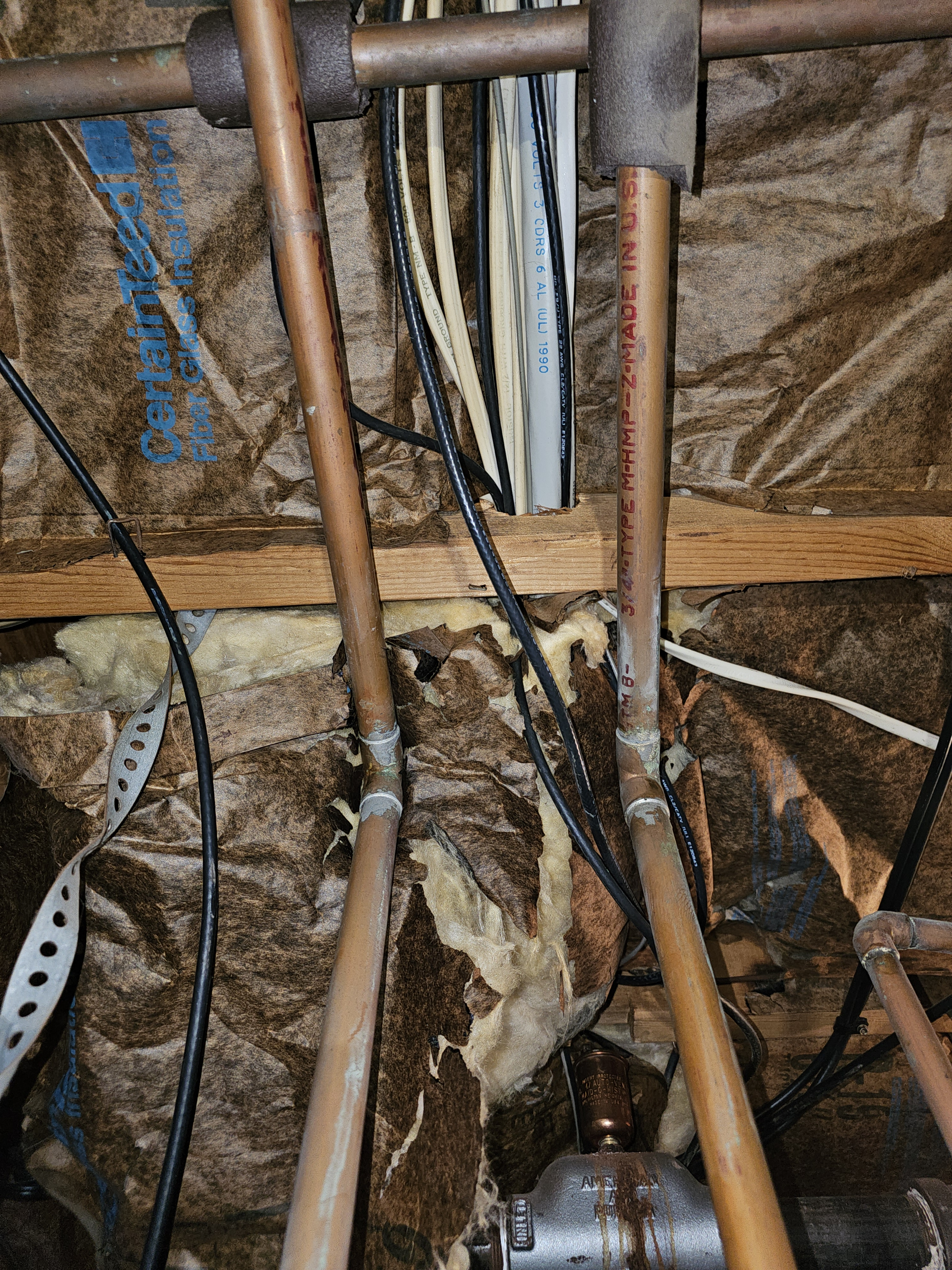
I went back and looked more carefully at the pictures in the original post,
#3#4 in particular was helpful. I'm going to amend my answer a bit. If one of the balancing* valves still works you could isolate and flush the other loop by shutting the balancing valve that works and one of the isolation valves on the circulator. If you did that, and got air when flushing, that would confirm the diagnosis that air in the loop was the underlying problem. I always flush with a hose into a bucket with some water into it so I can see bubbles if air is coming out.
That isn't a long-term fix though, the balancing valve needs to be fixed. That valve looks like it has a core that could be screwed out and replaced. But you'd have to find a replacement core, and drain the system. My position is that if I'm draining, I'm replacing old valves with quarter turn ball valves while I have it dry. I'd cut out that brass fitting and put in a threaded tee with a quarter turn boiler drain in the tee and a quarter turn ball valve between the tee and the circulator. I'd probably do it on both sides while I was at it.
*(I retract my earlier position that they might really be isolation valves).1 -
Those may be butterfly type purge valves. Really any type of valve can be used as a iso and balance valve.
For the least amount of connections and a purge valve that flows either direction, these Webstone work wellBob "hot rod" Rohr
trainer for Caleffi NA
Living the hydronic dream1 -
You read my mind. Exactly the plan.DCContrarian said:I went back and looked more carefully at the pictures in the original post,#3#4 in particular was helpful. I'm going to amend my answer a bit. If one of the balancing* valves still works you could isolate and flush the other loop by shutting the balancing valve that works and one of the isolation valves on the circulator. If you did that, and got air when flushing, that would confirm the diagnosis that air in the loop was the underlying problem. I always flush with a hose into a bucket with some water into it so I can see bubbles if air is coming out. That isn't a long-term fix though, the balancing valve needs to be fixed. That valve looks like it has a core that could be screwed out and replaced. But you'd have to find a replacement core, and drain the system. My position is that if I'm draining, I'm replacing old valves with quarter turn ball valves while I have it dry. I'd cut out that brass fitting and put in a threaded tee with a quarter turn boiler drain in the tee and a quarter turn ball valve between the tee and the circulator. I'd probably do it on both sides while I was at it. *(I retract my earlier position that they might really be isolation valves).0 -
Wish I saw that sooner. Already put together a ballvalve + T with drain fitting for each loop. Gonna install nowhot_rod said:Those may be butterfly type purge valves. Really any type of valve can be used as a iso and balance valve.
For the least amount of connections and a purge valve that flows either direction, these Webstone work well0 -
Wish I saw that sooner. Already put together a ballvalve + T with drain fitting for each loop. Gonna install nowHot_n_Cold said:hot_rod said:Those may be butterfly type purge valves. Really any type of valve can be used as a iso and balance valve.
For the least amount of connections and a purge valve that flows either direction, these Webstone work well
I was the one who led you astray there. The irony is in my own home I have the Webstones.1 -
Lol it's alright. I appreciate the help!DCContrarian said:
I was the one who led you astray there. The irony is in my own home I have the Webstones.
Wish I saw that sooner. Already put together a ballvalve + T with drain fitting for each loop. Gonna install nowhot_rod said:Those may be butterfly type purge valves. Really any type of valve can be used as a iso and balance valve.
For the least amount of connections and a purge valve that flows either direction, these Webstone work well
I got these made up.
Also, how do I get the air out that's downstream from these ballvalves?
I guess I could leave the water level below the breaks in the lines for minimal air and then just let the air scoop do it's job? 0
0 -
Looks good.Hot_n_Cold said:
Lol it's alright. I appreciate the help!
I got these made up.
Also, how do I get the air out that's downstream from these ballvalves?
I guess I could leave the water level below the breaks in the lines for minimal air and then just let the air scoop do it's job?
What you do is fill the system with water, open the makeup water valve. Close the isolation valve on that loop, and then open the drain valve. Water will fill the loop and push out the air. Once you get a steady stream of water, close the drain and open the isolation valve. Any air between the circulator and the valve will rise up and into the loop. Then close the isolation and open the drain again until the air bubbles out. Depending on the system you may have to repeat a couple of times to get all the air out.1 -
Sounds good. I actually did the repair on both loops on that zone. So I assume just do that with both loops right?DCContrarian said:Lol it's alright. I appreciate the help!
Looks good. What you do is fill the system with water, open the makeup water valve. Close the isolation valve on that loop, and then open the drain valve. Water will fill the loop and push out the air. Once you get a steady stream of water, close the drain and open the isolation valve. Any air between the circulator and the valve will rise up and into the loop. Then close the isolation and open the drain again until the air bubbles out. Depending on the system you may have to repeat a couple of times to get all the air out.
I got these made up.
Also, how do I get the air out that's downstream from these ballvalves?
I guess I could leave the water level below the breaks in the lines for minimal air and then just let the air scoop do it's job?0 -
Sounds good. I actually did the repair on both loops on that zone. So I assume just do that with both loops right?Hot_n_Cold said:DCContrarian said:
Looks good.Hot_n_Cold said:
Lol it's alright. I appreciate the help!
I got these made up.
Also, how do I get the air out that's downstream from these ballvalves?
I guess I could leave the water level below the breaks in the lines for minimal air and then just let the air scoop do it's job?
What you do is fill the system with water, open the makeup water valve. Close the isolation valve on that loop, and then open the drain valve. Water will fill the loop and push out the air. Once you get a steady stream of water, close the drain and open the isolation valve. Any air between the circulator and the valve will rise up and into the loop. Then close the isolation and open the drain again until the air bubbles out. Depending on the system you may have to repeat a couple of times to get all the air out.
Yep. Air has a nasty habit of moving around so you may have to purge the other zones too.
Did you examine the valve you took out? Was it suspect?1 -
Yessir. Got it fixed! Everyone's happy. Balanced it so both return pipes on that zone are at the same temp.DCContrarian said:
Yep. Air has a nasty habit of moving around so you may have to purge the other zones too. Did you examine the valve you took out? Was it suspect?
Sounds good. I actually did the repair on both loops on that zone. So I assume just do that with both loops right?DCContrarian said:Lol it's alright. I appreciate the help!
Looks good. What you do is fill the system with water, open the makeup water valve. Close the isolation valve on that loop, and then open the drain valve. Water will fill the loop and push out the air. Once you get a steady stream of water, close the drain and open the isolation valve. Any air between the circulator and the valve will rise up and into the loop. Then close the isolation and open the drain again until the air bubbles out. Depending on the system you may have to repeat a couple of times to get all the air out.
I got these made up.
Also, howgi GG do I get the air out that's downstream from these ballvalves?
I guess I could leave the ÿhv ft g vyvh g c c level below the breaks in the lines for minimal air and then just let the air scoop do it's job? 


Here's some pics for your viewing pleasure.
For some reason they were added in the quote.
Big lessons learned on this job!
It seems like the metals wore off and wouldn't seal properly, thus not allowing a proper isolation purge.
Even verified afterwards by taking each valve and dumping some water in one end while the valve is positioned closed. Both leaked profusely.
I truly appreciate all the help, I hope good things happen for everyone who contributed!!!
Also note that in the Pic showing the inside of the valve, I loosened the packing nut. So, normally that damper/valve inside would sit flush against the back of the fitting. The huge gap wasn't there until I loosened the packing nut. Problem was the metals weren't sealing. Terrible design IMO.


0 -
Good work. And I like the brass caps on the drains, belts and suspenders.
Props to the guy at the supply house who suggested the balancing valve might be the problem. Maybe he's seen it before.0


Categories
- All Categories
- 87.5K THE MAIN WALL
- 3.3K A-C, Heat Pumps & Refrigeration
- 59 Biomass
- 429 Carbon Monoxide Awareness
- 124 Chimneys & Flues
- 2.2K Domestic Hot Water
- 5.9K Gas Heating
- 118 Geothermal
- 168 Indoor-Air Quality
- 3.8K Oil Heating
- 78 Pipe Deterioration
- 1K Plumbing
- 6.6K Radiant Heating
- 394 Solar
- 15.9K Strictly Steam
- 3.5K Thermostats and Controls
- 56 Water Quality
- 50 Industry Classes
- 50 Job Opportunities
- 18 Recall Announcements