Welcome! Here are the website rules, as well as some tips for using this forum.
Need to contact us? Visit https://heatinghelp.com/contact-us/.
Click here to Find a Contractor in your area.
If our community has helped you, please consider making a contribution to support this website. Thanks!
White-Rodgers Universal Hot Surface Ignition Control: problem.............
Options

ChuckKeysor
Member Posts: 17
in Gas Heating
Hello Furnace experts......
I just got done installing a White-Rodgers "Universal Hot Surface Ignition Control" in my old Weil-McLain VHE-6 furnace/boiler. The original controller called for in my VHE-6 manual has been replaced with this universal module. Installation seemed straight forward.
Upon power up, the only thing that happened was an error code of three yellow blinks, which in the new unit's manual says: " Measure AC voltage between terminal L1 and TH. If voltage is approximately 145 vac, polarity is reversed; reverse secondary leads on control transformer. Correct reading should be approximately 95 VAC." I measured 39 VAC. And their suggestion of reversing the secondary leads of the 24vac control transformer doesn't make any sense......... as one side of the 24vac transformer output has always been hard wired to ground for the 30 years this furnace has been in service......
a) I looked on the White Rodgers website, and could not locate a tech support email address or phone number for this type of product............. Any suggestions of where I can call or email????
b) Does anyone have any suggestions as to what I might have done wrong.....
Thank you,,,,,,,,,,, Chuck
0
Comments
-
are you using 50E47-170, control that comes in the WM part number 510-811-477 ?
Edward Young Retired
After you make that expensive repair and you still have the same problem, What will you check next?
0 -
Common from the transformer should go the chassis ground and the TR on the 50E47 control.
R from the 24 V transformer should not go to ground...
R from the transformer should go in series to any 24V limits and the N/O contacts of the relay operated by the thermostat and then to the TH terminal on the 50E47. (not sure of the colors of the wires on that relay but I can find the wiring diagram if it is not on the boiler.)
It is important to get the TR to the common and grounded side of the 24V transformer secondary. That is because the control uses a flame sensing method called Flame Rectification. and proper grounding is an important part of the flame sensing process in the WR 50E47 control.Edward Young Retired
After you make that expensive repair and you still have the same problem, What will you check next?
1 -
This might be your old wiring diagram

and this is the new control on that diagram
Edward Young Retired
After you make that expensive repair and you still have the same problem, What will you check next?
1 -
Hello Ed!!!!!!!!!!! I got home about an hour ago, and found your great reply!
I have attached my schematic, sitting next to your schematic. I have tried to compare my unit's schematic with yours, and found a few differences. (Using my schematic, it seemed like this was a pretty easy install, until I powered it up!!!!)
In the morning, I will take your new schematic and important directions and go to my furnace and see if I can get things straight. I'll report back later in the morning......... (I won't want to get out of bed, as it is cold in my house.....)
Thank you, Chuck
 1
1 -
Oooops, I didn't answer your first question which was: "are you using 50E47-170, control that comes in the WM part number 510-811-477 ?" No.
The manual that came with my furnace said the WR part number was: 50E47-150. It said the WM part number was: 511-330-129.
When I went to order the 50E47-150, I was told that it has been replaced with the 50E47-843. So that is what I ordered, and what I installed in my furnace yesterday.
And I am using the separate flame sensor WR 760-802.
The instructions for the new replacement WR ignition control listed the 50E47-150, so I felt what I bought must be right. (The instructions said to replace the 50E47-150, that I have to use the "B" jumper block.)
Thank you again, Chuck0 -
It dawned on me that I should show what the wiring diagram was in the W-R instruction manual that came with the 50E47-843 "Universal Hot Surface Ignition Control" module. That appears below. NOTE, I USED FIG. 1
I see in figure 1, that L2 of the module is directly connected to ground. In figure 3, L2 of the module is connected to "L2" of the incoming power, which is neutral, which is grounded........... hmmm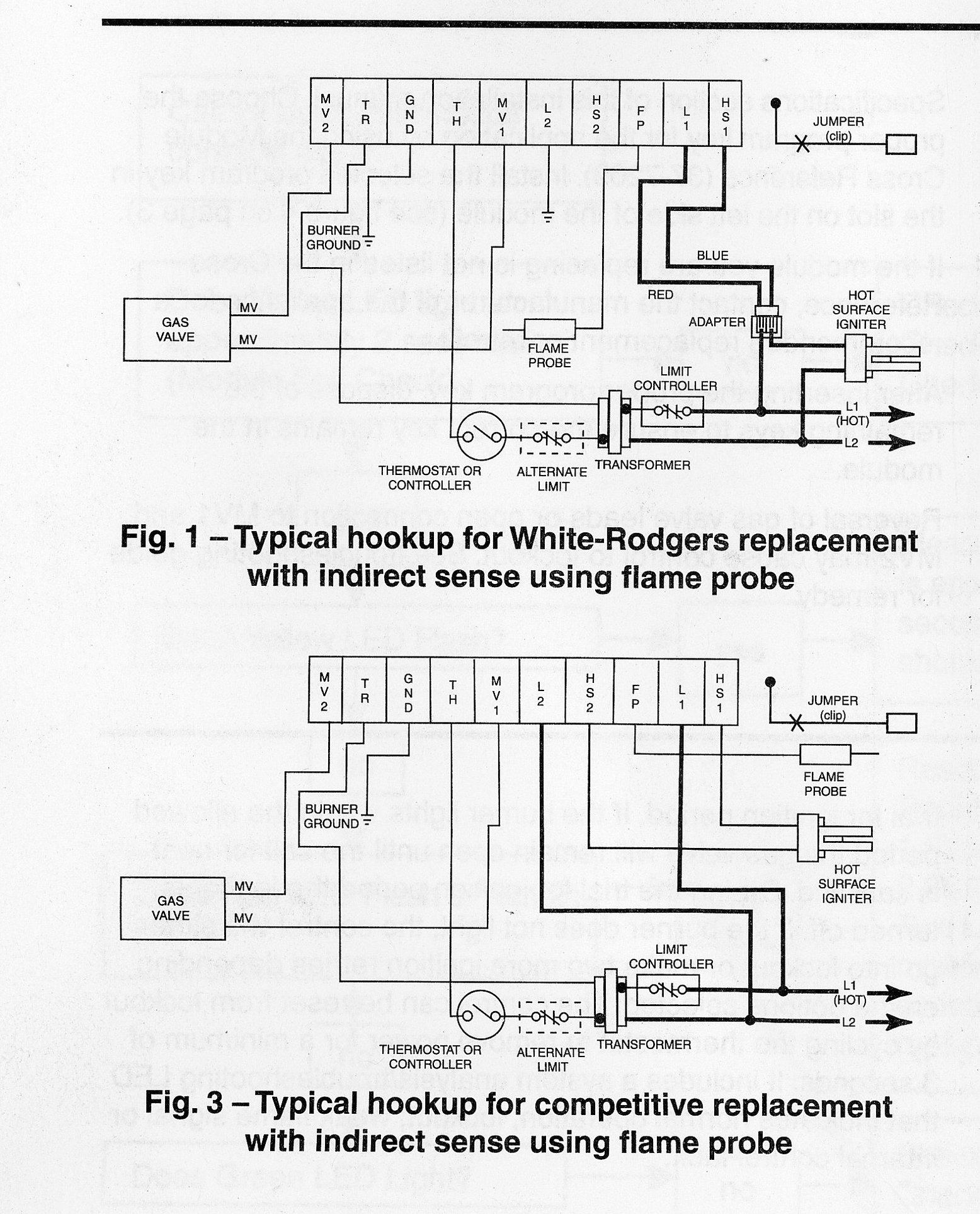
0 -
Thank you Ed for your help. I did in fact have a bad ground connection just as you theorized, and now my unit is working!!!! Thank you, Chuck0
-
Evertbody can use a little help now and then Chuck just like these ladies. Please help the Franciscan Sisters of Kansas City with their boiler. Normally the first or second post on the wall.0
-
UPDATE: I did get my White-Rodgers controller to work, and as Ed suggested, I in fact had a bad ground connection! Thank you Ed! I previously sent Ed a private message, but forgot the public thanks............ oops. This is a great forum, and people like Ed help to keep it a success for people looking for help!
Chuck0

Categories
- All Categories
- 87.7K THE MAIN WALL
- 3.3K A-C, Heat Pumps & Refrigeration
- 59 Biomass
- 430 Carbon Monoxide Awareness
- 128 Chimneys & Flues
- 2.2K Domestic Hot Water
- 5.9K Gas Heating
- 121 Geothermal
- 170 Indoor-Air Quality
- 3.8K Oil Heating
- 79 Pipe Deterioration
- 1K Plumbing
- 6.6K Radiant Heating
- 396 Solar
- 16K Strictly Steam
- 3.5K Thermostats and Controls
- 56 Water Quality
- 51 Industry Classes
- 51 Job Opportunities
- 17 Recall Announcements