Welcome! Here are the website rules, as well as some tips for using this forum.
Need to contact us? Visit https://heatinghelp.com/contact-us/.
Click here to Find a Contractor in your area.
If our community has helped you, please consider making a contribution to support this website. Thanks!
Need some help with hydronic design
Options
Mike_Sheppard
Member Posts: 698
Edit: added second drawing
Good evening guys,
I was wondering if anyone would be willing to give me some guidance on this. This is the job I posted about before, where we lost the bid and they gave the job to the low bidder. They royally messed it up and they're struggling to keep the heat on in the building - an old folks nursing home. I would like to propose a complete solution, not a patch job. Including new boilers, piping, venting, and controls. This is a large customer, 30+ properties and we have their maintenance contract. If they don't approve a complete fix I am going to walk away. But I at least would like to provide them a full solution. I attached a picture of what I had in my head.
I have no idea if this would be the best way to do it. There are two Weil McLain Slimfit 550 boilers. There is a water source loop that stays at 70 degrees during the winter. And there is a 100% outdoor make-up air coil also in the boiler room that needs hotter supply water as it gets colder outside to maintain a 68 degree supply air temp to the building. The pumps, mixing valve, and diverting valve are there already piped to the loop / coil how I drew them. (sorry for the messy drawing, I'm not good with hydrosketch yet).
Am I on the right track? Or is this not even close? I know the boiler piping isn't drawing 100% accurately and if I am not mistaken the two secondary loops with the 3-way valves would need a check valve on them.
Never stop learning.
0
Comments
-
Need closely spaced T's. Or a hydraulic separator/low-loss header.0
-
I'd probably be piping the P/S so that the boilers are on their own sub-header hydraulically separated from the primary loop (with its own circ) and then run the MUA off a HX in said primary loop with glycol to prevent freezing and cold sammiches with 100% OA, but that's assuming my MN climate.0
-
Hydraulic separation is the goal. I really like the simplification of design using a dedicated separator device like Caleffi's. But Taco makes them and I think Spirovent does too.0
-
How about this one? I do like the idea of a buffer tank, especially because of the added water volume. But if I don't necessarily need to add that extra cost to the job I'd prefer to leave it out of this one.

Never stop learning.0 -
Wouldn’t you want your water source mixing valve set up as your make up air set up is pumping from the valve not through . I think I would have the tees upstream of the eliminator and pump .i would leave the sensor downstream of the water source loop pump . Also don’t forget checks on pumps and on the return for your water source loop in case that hi temp outside air coil migrates .peace and good luck clammy
R.A. Calmbacher L.L.C. HVAC
NJ Master HVAC Lic.
Mahwah, NJ
Specializing in steam and hydronic heating0 -
@clammy
I actually drew the condenser loop backwards. You’re right about the tees upstream. That is actually how they are already, I just drew it wrong. The pump and air separator should have been on the left side of the tees.
As for the pump, what is the reasoning for having the pump on the outlet side of the valve (mixing) rather than pumping into the valve (diverting)? Just got my own education.
My thought was, having the pump where it is pumping into the valve, it would allow constant circulation through the header for the boilers. If I were to put the pump on the outlet of that valve it would just sit there and pump in a circle through the close tees and water source loop.Never stop learning.0 -
A sep would give you 4 critical functions aid, dirt, separation, and magnetic partial removalBob "hot rod" Rohr
trainer for Caleffi NA
Living the hydronic dream0 -
@hot_rod unfortunately they’re stuck with the one they have now. Unless you mean putting one on the boiler piping.
Their system, which was retrofitted with these boilers a month ago, is a complete disaster. They barely have heat and their make-up air system is completely non-operational at the moment. I just want to give them a good piping option to get things up and running reliably.Never stop learning.0 -
I think I would look at the btu requirements for water source loop and the make up air ,each requires a total different temp requirements .i It may pay to use a primary loop and pipe the make up first and then water source ,set your boiler to make up air systems curve and let the the water source loop mix down .i m not familiar w the controls on the slim fir I gues a good read through would be a great idea and possible talk to Weil tech services they may shed some light if not do the math and work from that . I think I would figure out the min and max requirement for both water source and make up . I stinks doing follow up every body on the cheap until it don’t work then they want miracles also on the cheap , possibly they should have hire a design engineer but that was to much money lol sometimes you can’t fix penny wise dollar foolish peace and good luck clammy
R.A. Calmbacher L.L.C. HVAC
NJ Master HVAC Lic.
Mahwah, NJ
Specializing in steam and hydronic heating0 -
I ve always pumped away from a mix or divert or valve and installed checks and a globe valve to throttle the mix .It s just the way it’s been done and it s the way I ve seen it done on large commercial stuff hospitals and such done in the 40 and 50 now rarely is it seen and everybody just uses a 2 way and forgets none of the good stuff just on and off no supply air sensor to mod the valve .just a race to the cheapest and hopefully there will be someone who can fiddle w it and squeeze it to work .i was lucky to work for a company who had a ME and PE there and they where great I learned a lot from both guys and they always answered a question and it was followed up by giving me books and literature ,I was lucky most never used the oppurinty to pick there skulls but I did .no one knows it all and it never comes over nite it a daily thing of a little bit every day that’s how it done and usually try to hang w those smarter then you .peace and good luck clammy
R.A. Calmbacher L.L.C. HVAC
NJ Master HVAC Lic.
Mahwah, NJ
Specializing in steam and hydronic heating 1
1 -
I believe I would install the correct size pump on the ground loop and then do injection mixing into the ground loop. That gives you the option of slowing down the injection pump if the boiler return temp drops to low.
For the make up air, I would probably use a variable speed setpoint circulator and run the water in at boiler temp. The circulator will operate off of the supply air temp, speeding up and slowing down as needed.
And yes, you should decouple the boilers either via primary secondary or a low loss header, or Hydraulic seperator. They are high temp boilers supplying low temp loops, no?0 -
@Harvey Ramer these new boilers are condensing. So they can run at low temp. If the darn MUA unit wasn’t this this would be extremely simple. I like the idea of an ECM pump, I will consider that.
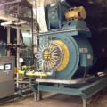
The water source loop is large, the pump for that is correct. It’s 8 inch pipe and a large floor mounted pump. It uses a cooling tower during the summer for cooling. Since these buildings have a lot of core load they don’t need much heat addition from the boilers during the winter. One 500,000 btu boiler was enough to satisfy the heating load.
I went there yesterday and did some experiments. Set the boilers up to run outdoor air reset. That is working much better but the piping and pumping is still wrong. Have to lock the 3-way valve open to the MUA unit to get decent enough flow to run the boilers.
@clammy , the sad thing is, they DID hire a design engineer. They installed it as the engineer drew it. The engineer removed the 3-way for the water source loop and installed a 2-way. Then drew the new boilers piped in series with the main circulator pumps, instead of primary-secondary. The gas lines are also undersized and the venting is completely wrong. I don’t think the engineer knew what kind of system it was. He labeled the boilers and the water source loop as operating at 180 degrees. He labeled the pipes “dual temperature” like a 2 pipe changeover system that uses boilers and chillers. But that’s not what it is at all. The whole job was doomed from the get-go.Never stop learning.0 -
Mike just wondering was there any heat exchanger between the cooling tower and the water source loop or are they just shutting isolation valves and switching pumps over and calling it a day Peace and good luck clammy
R.A. Calmbacher L.L.C. HVAC
NJ Master HVAC Lic.
Mahwah, NJ
Specializing in steam and hydronic heating0 -
@clammy yes, there is a plate and frame heat exchanger separating the cooling tower and closed loop.
Picture attached.Never stop learning.0


Categories
- All Categories
- 87.6K THE MAIN WALL
- 3.3K A-C, Heat Pumps & Refrigeration
- 59 Biomass
- 430 Carbon Monoxide Awareness
- 124 Chimneys & Flues
- 2.2K Domestic Hot Water
- 5.9K Gas Heating
- 120 Geothermal
- 169 Indoor-Air Quality
- 3.8K Oil Heating
- 78 Pipe Deterioration
- 1K Plumbing
- 6.6K Radiant Heating
- 396 Solar
- 16K Strictly Steam
- 3.5K Thermostats and Controls
- 56 Water Quality
- 51 Industry Classes
- 51 Job Opportunities
- 18 Recall Announcements