Wiring BVS+FRS+aquastat to Taco SR502 ?

Current config is:
Burnham Series 2 boiler (P-206A-WNI) stamped 1994
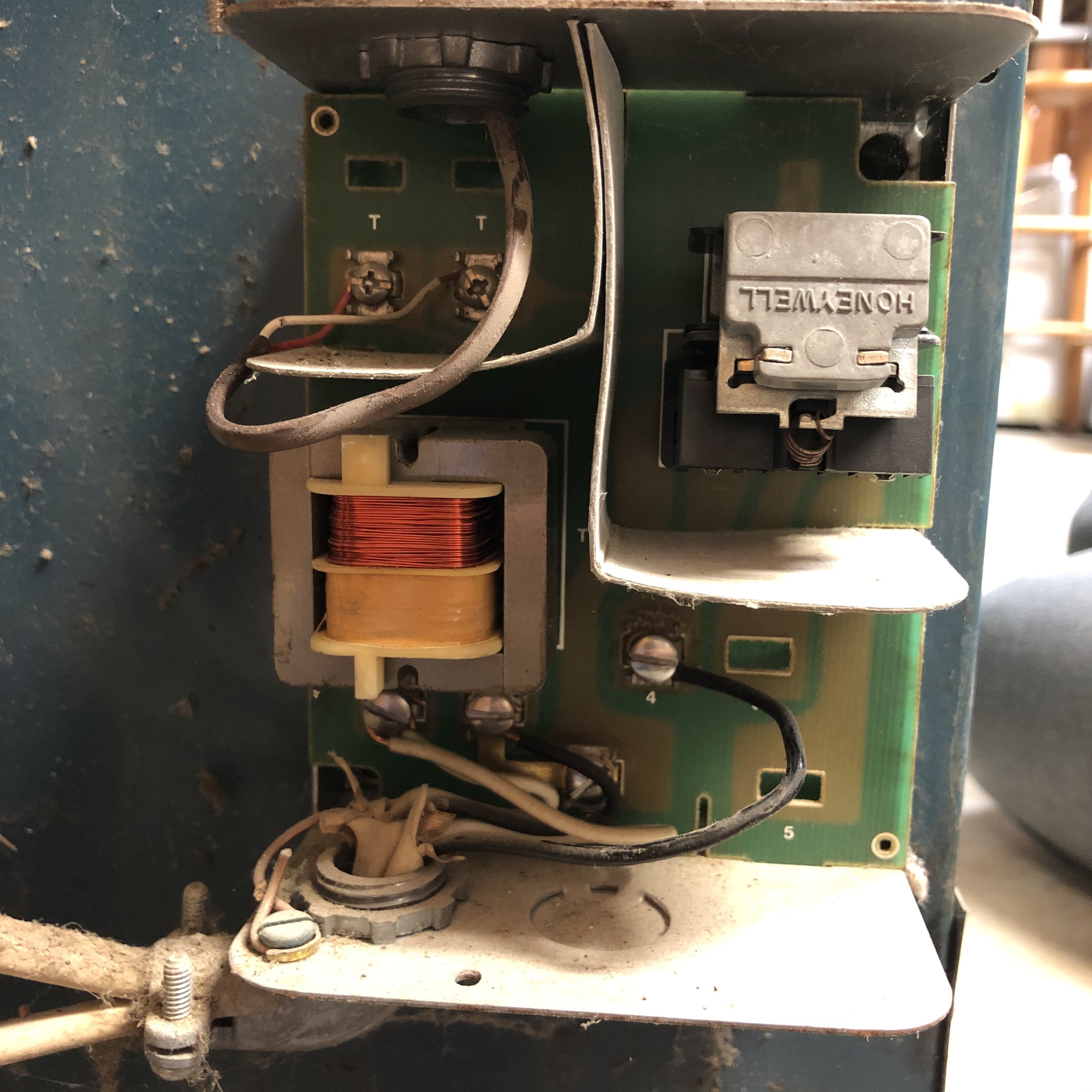
Honeywell S8610M
Honeywell R8285D connected to thermostat A, pump A, and S8610M.
Honeywell RA89A connected to thermostat B, and pump B.
Problem is thermostat B had no connection to the boiler to call for heat - it would pump cold water through it's loop.
Searched and read forums for similar situations and saw a recommendation to replace the two Honeywell relays with a Taco SR502 (SR502-4 wiring guide). I believe I have all the wiring mapped out except for the sensor circuit.
Currently there is a wire running from the Y-terminal on the R8285D serially through the blocked vent, flame rollout, and aquastat sensors before connecting to the TH-W connector on the S8610M. I'm trying to figure out where this would connect on the Taco. I suspect the 24VAC (top terminal?) on the upper left of the board?


Thanks,
Arryn
Comments
-
#1 MOST IMPORTANT .... DO NOT BYPASS ANY SAFETY OR LIMIT DEVICES IN THE GAS VALVE /BURNER CIRCUIT WITH YOUR RE-DESIGN.
#2 Look for a wiring diagram on the boiler and do your best to place the wiring in the exact same configuration as the manufacturer original specifications.
#3 Don't re-invent the wheel The SR502 is very simple and takes only a minimum amount of wiring knowledge to install it properly.
In the original boiler wiring diagram, there is a place for the room thermostat. You will connect the X X end switch of the Taco SR502 to the thermostat location on the boiler
Now take your zone A thermostat wires and connect them to the SR502 then take the circulator that is connected to the boiler control R8285D and connect it to the SR502. This assumes that the SR502 is already wired to replace the RA89A and has zone 1 available for the zone A thermostat and zone A circulator
The R8285A is still needed for the step down to 24 v to operate the gas valve thru the limits and safety controls.
I know the boiler diagram may not be exactly what you have, that is why you should locate the diagram inside the boiler access door and check that the wiring is as close to original **** possible
Finnaly: I realized that my drawing utilized Zone #3 for your zone A thermostat and zone A circulator. I did that on purpose to see if you are paying attention!Edward Young Retired
After you make that expensive repair and you still have the same problem, What will you check next?
0 -
follow-up
Once you believe that you are correctly wired, operate zone A to see if the Zone A thermostat operates the zone A circulator and also operates the burner. Once you have determined this is correct, test the limit circuit by closing a valve to stop the water from circulating and see if the burner shuts down if the water temperature exceeds the limit setting. If the limit operates properly the burner should shut off. Open the valve you used for the test, watch the water temperature drop and the burner should come back on once the water temperature drops below the limit setting.
Do the same test on Zone B. If you get the same results, you are good to go. If the burner does not shut off on either zone then get a professional to check it out.Edward Young Retired
After you make that expensive repair and you still have the same problem, What will you check next?
0 -
I wouldn't close a valve and deadhead a circulator. I would remove the wire that operates the circulator.
Also, let it cool down before reconnecting the circulator. Don't pump room temp water right back into a 200° boiler.There was an error rendering this rich post.
0 -
Factory wiring shouldn't and doesn't need to be altered other than bringing the circulator wiring into your new zone board. Get the SR502. Wire up the zones. Run a thermostat wire from the XX dry contacts on the SR502 to the terminals on the control relay in the boiler cabinet that has the red and white wires connected to it in your third pic. Those existing red and white wires will now move to the SR502.0
-
HVAC NUT has the right idea. The third picture in my post shows the details on paper. Here it is again.

the boiler diagram is not exactly your heater but it is close!Edward Young Retired
After you make that expensive repair and you still have the same problem, What will you check next?
0 -
Hi Folks,
i'm going to try and make better (more complete) current and planned wiring diagrams. But in short, my plan is to replace the R8285 and RA89 with the Taco SR502. Assuming I can keep the limit and safety devices...0 -
Just put the FRS and BVS in series before the gas valve if you get stuck. That "CO2 Sensor" on your diagram, by the way, senses heat, not "carbon dioxide", and not carbon monoxide either. Are you sure you should be doing this work?Contact John "JohnNY" Cataneo, NYC Master Plumber, Lic 1784
Consulting & Troubleshooting
Heating in NYC or NJ.
Classes0 -
You don’t want to remove the R8285. It is part of the manufactures design that was approved for safe operation by such agencies like ASME, I=B=R , NFPA and other Boiler Manufacturing Licensing agencies. Once you redesign the control system to something other than the manufacturers specifications, you are voiding all the approvals and protections afforded by those agencies. If something fails that gets your insurance company involved... you may be on the hook without coverage
Edward Young Retired
After you make that expensive repair and you still have the same problem, What will you check next?
0 -
Here's the current wiring setup:

0 -
And what I was trying to achieve. Except I can't figure out where to wire in the safety circuit (ends in a question mark). Where should that question mark be connected on the Taco?

0 -
I also stumbled across a possible solution that would replace the RA89A relay with a R845A relay which would allow me to connect the two relays so that either thermostats call for heat would be passed on to the boiler.
0 -
Yeah. Sorry. Described it correctly in the write up, but labeled it wrong on the diagram.JohnNY said:Just put the FRS and BVS in series before the gas valve if you get stuck. That "CO2 Sensor" on your diagram, by the way, senses heat, not "carbon dioxide", and not carbon monoxide either. Are you sure you should be doing this work?
 1
1 -
You dont do anything with the safety circuit. It stays on the Y terminal.
Rewire EVERYTHING back to factory specs.
All you need to do is connect the XX isolated end switch on the SR502 to R and G on the R8285.
Take the existing line and low volt wiring for the zone currently in the R8285 and move it to the SR502.
Nothing at the ignition control module should be touched.
Why would you even think what you drew was ok?0 -
I didn't think it was ok. That's why I was asking for help. Sincerely, thank-you for your concern. Please note that I started this thread expressly because I'm trying to figure out how to maintain the safety devices in this system - I do NOT want to blow my house up.HVACNUT said:You dont do anything with the safety circuit. It stays on the Y terminal.
Rewire EVERYTHING back to factory specs.
All you need to do is connect the XX isolated end switch on the SR502 to R and G on the R8285.
Take the existing line and low volt wiring for the zone currently in the R8285 and move it to the SR502.
Nothing at the ignition control module should be touched.
Why would you even think what you drew was ok?
Don't worry. There's nothing to rewire because I haven't touched anything yet. I'm still trying to figure out the best course of action. The system is still as I found it (in it's factory spec'd state?), pumping cold water around the 2nd loop (2nd floor). This seems like a pretty bad design if this is how the factory designed it.
I don't understand how moving the line and low voltage wiring from the R8285 (zone 1) will allow the thermostat attached to the RA89A (zone 2) to trigger the boiler.
What I was hoping to achieve was a system that allows both thermostats to trigger the boiler (and associated circulator) while being as simple as possible. To that end I was hoping a single Taco SR502 would replace the two Honeywell relays. I was hoping to avoid doubling the complexity of the system.
I'm coming to the conclusion that the Taco unit is the wrong tool for this job. I was told the SR502-4 was a suitable replacement for the two existing relays, but maybe not.0 -
To help anyone else in my shoes, here's my solution.
I scrapped the plan to use the Taco. It cannot replace the Honeywell relays. At least, not in my case.
I removed the Honeywell RA89A and replaced it with an R845A. This allowed me to connect the 2nd zone to the boiler controls. Now both zones can activate their respective circulator and the boiler.
The only hiccup was I initially wired R845A terminals 5&6 to the R8285D R&Y backwards so one Nest wasn't getting power. Flipped the wires and it's all good.0 -
Is the R8285D still operating one of the circulators as in the original factory diagram? If yes.. then when the zone controlled by the RA845a will operate both circulators at the same time. you would need another RA845a for the other circulator.
The better option is the SR502 wired in as I indicated earlier in this post.
In the diagram you posted with the question mark ? asking where do you put the limit circuit... you leave it on the Y terminal. the Y gets power from R thru the relay. See the other yellow wire sneaking into the line voltage side of the junction box? That goes to a normally open NO set of contacts on the relay. the other side of the NO contacts is the red wire sneaking into the line voltage side of the junction box.
That is why everyone is saying DONT FU*** WITH THE FACTORY WIRING ! ................................................................................(Fudge)Edward Young Retired
After you make that expensive repair and you still have the same problem, What will you check next?
0 -
I had to physically check, but the second zone (upstairs) that is attached to the R845A and it's circulator operate independently of the first zone (downstairs). I checked by turning up the thermostat on the 2nd zone and checked the pumps, pipe, and radiators. With the upstairs thermostat calling for heat and downstairs not, only the upstairs radiators got hot.
As a novice I'm confused by the conflict between "Don't fudge with the factory wiring!" vs. slide this SR502 into the middle of the factory wiring by moving the thermostat and circulator over, but leave the Y terminal alone.
Thank-you to those folks that responded and pushed me in the right direction (Ed, John, Steve, HVACNUT). RTFM is a good place to start - and ultimately gave me the correct solution. Figure 16 on zone wiring in the Burnham Series 2 boiler manual in my case.0


Categories
- All Categories
- 87.7K THE MAIN WALL
- 3.3K A-C, Heat Pumps & Refrigeration
- 59 Biomass
- 431 Carbon Monoxide Awareness
- 127 Chimneys & Flues
- 2.2K Domestic Hot Water
- 5.9K Gas Heating
- 121 Geothermal
- 170 Indoor-Air Quality
- 3.8K Oil Heating
- 79 Pipe Deterioration
- 1K Plumbing
- 6.6K Radiant Heating
- 396 Solar
- 16K Strictly Steam
- 3.5K Thermostats and Controls
- 56 Water Quality
- 51 Industry Classes
- 51 Job Opportunities
- 17 Recall Announcements