Welcome! Here are the website rules, as well as some tips for using this forum.
Need to contact us? Visit https://heatinghelp.com/contact-us/.
Click here to Find a Contractor in your area.
If our community has helped you, please consider making a contribution to support this website. Thanks!
One-Pipe 3-Circuit Monoflow System
Options
Mike_Sheppard
Member Posts: 698
Does anyone have experience with multi-circuit one pipe systems?
I came across another one today, this one with 3 circuits. If anyone remembers my last thread about a one-pipe system, it had a single abandoned monoflow tee in the return line at the boilers. This one is the same way. A single abandoned monoflow tee in the return.
The supply is 2.5 inch, and the three loops are 2 inch, and all return to a common 2 inch return. Does this seem right?
Never stop learning.
0
Comments
-
I tried to post a picture of it from my phone but I'm not sure if it worked or not. If not, I'll do it from the computer later today.
Edit: nvm it seems to have worked.Never stop learning.0 -
What's the problem Mike
There was an error rendering this rich post.
0 -
@Big Ed
Currently there is no problem. I'm just struggling to understand the concept of three 2 inch returns coming back to a single 2 inch return.Never stop learning.0 -
The other loops have a slower fluid velocity for greater delta T.Mike_Sheppard said:@Big Ed
Currently there is no problem. I'm just struggling to understand the concept of three 2 inch returns coming back to a single 2 inch return.
 1
1 -
Normally, the pipes are sized based on connected load, anticipated delta t at a given flow. If the boiler only has 2" return tapping, then I'm not surprised all combined returns are 2" as well. You'd need to do a reverse load survey, inventorying all radiators connected to a given main before you can determine the proper pipe size.Mike_Sheppard said:Does anyone have experience with multi-circuit one pipe systems?
I came across another one today, this one with 3 circuits. If anyone remembers my last thread about a one-pipe system, it had a single abandoned monoflow tee in the return line at the boilers. This one is the same way. A single abandoned monoflow tee in the return.
The supply is 2.5 inch, and the three loops are 2 inch, and all return to a common 2 inch return. Does this seem right?
As for the monoflo tee on the return, hard to say, but my gut tells me its to blend the hotter supply with the cooler return water to keep the boiler from condensing when doing a cold start up.
If the boilers been replaced, this was probably lost in the shuffle...
ME
0 -
-
I guess to truly figure it out the system would have to be reverse engineered. Each loop would have to have heat loss calculations done.
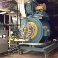
There are two boilers that aren’t original. They are piped primary secondary with common manifolds. Both rated for 305,000 btu. Cast iron sectionals. With a 20 degree delta T we’d be looking for 61 gpm. Basing that off the boiler output though and they’re likely oversized. Identical to the last monoflow system I posted about but this one has three loops instead of two.
Each boiler has 2 inch tappings. Each loop has a balance valve at the end but they’re all wide open and each loop does see about a 20* delta T. I used Dan’s ballpark friction loss formula and the friction loss through the longest loop pretty much falls right on the pump curve where it should be.
So I’m guessing each loop will be looking for about 20gpm, 200,000 btu/hr. With 2 inch pipe that’s around 1.9 feet per second velocity.
How important is velocity for diverter tees? Does it matter? I guess they’ll still create a pressure drop either way.
I guess they could have dropped the loop pipe sizes down to 1-1/4 but then friction loss would have been about two times greater which would require a larger pump.
So now I’m wondering how the velocity is correlating with the delta T in each loop. If the pipe was reduced to 1-1/4, and a larger pump was installed to overcome the added friction loss, while still providing 20 gpm to each loop, the velocity is going to go up from 1.9 to 4.3. The water is moving faster so it isn’t staying in each convector as long, but 20gpm is 20gpm so the delta T across the loop should stay the same.
Please forgive my random questions... it’s 5am, been running a service call since 3am, now I’m waiting on my next job and as usual my mind is going a million miles per hour. Can’t stop thinking about these questions. I need to seek help. Lol
The system is working fine, I’m just asking these questions as a way of trying to learn.Never stop learning.0 -
Higher delta v leads to lower delta T in circuit and higher delta P through fittings, and as you mentioned, larger pump.0
-
But if there is still 20 gpm, whether there velocity is higher or lower, would the delta T be the same? I know If velocity is too high you get laminar flow and that’s another issue.
Would 20gpm at 2fps transfer more heat than 20gpm at 4fps?Never stop learning.0 -
Pipe size is fixed. So fps is tied to gpm by pipe cross section.
If volumetric flow rate is fixed, then delta T depends on edr based on water temperature and room heat loss.
In design phase they weighed bigger pump and faster water velocity vs bigger pipe slower water velocity.0 -
I’m just thinking of hypotheticals.
2 inch pipe with 20gpm
1-1/4 pipe with 20gpm
Both connected to the same load
Are they going to transfer the same amount of heat, even though the velocity is different?Never stop learning.0 -
@Mike_Sheppard same flow same heat transfer as long as you have the same baseboard or radiation.
Increased velocity helps with heat transfer (turbulent flow) laminar flow reduces heat transfer in the baseboard or rad. But with the same flow you get the same heat transfer0 -
@EBEBRATT-Ed
Thanks for clarifying that. That's what I thought, it seemed to make sense.
So I guess perhaps they went with larger pipes than necessary in the three loops to reduce friction loss, allowing for a smaller pump. That's all that would make sense to me here.
Thanks to everyone for all of the input! Learning a lot.Never stop learning.1 -
If it makes you feel any better, I have YET to see a system running at 100% of capacity, even at design conditions, and even on jobs that I did the loss calcs, gain calcs and set the physical plant. Best that I have seen at design condition (bang bang boiler, and pump) is a 50% duty cycle. What this tells me is that there is a WHOLE lot of reality that kicks in and overrides theory, including internal gains, external (solar) gains and what I call the flywheel mass effect.
And FWIW, primary secondary doesn't protect a boiler as well as a non electric TRV (Caleffi, Danfoss/ESBE,Honeywell) will do.
And yes, by doing a heat loss calculation, backed up with a good blower door test, you would be able to fine tune the required water supply temperatures, and may very well result in a significant reduction in discharge temperatures and required flows. With this being standing cast iron radiators, the need for maintaining "sweep velocities" (4 to 5 FPS) in your system fluid are less important. Dirt and air will separate out in the radiation and boilers and not be a problem as it pertains to air "hang up".
ME1 -
At low velocity, say 2 fps or below the water does not carry the air along as well and you may have trouble purging and keeping good heat transfer. You want water touching steel as much as possible to transfer energy to the load.
Chapter 11 in Modern Hydronic Heating has a good section on divertor tee systems. It takes you step by step from load calc, pipe sizing, and circulator sizing.
The concept of a single pipe system is attractive, but the sizing and balance takes some time.Bob "hot rod" Rohr
trainer for Caleffi NA
Living the hydronic dream1 -
@hot rod
I read about that 2fps last night. So the pump in question was doing about 60gpm. It splits at the end into three single pipe loops. I have no way of telling the flow through each loop but I’m assuming they would be somewhat equal at around 20gpm each. 2 inch pipe, 20gpm, is less than 2fps. About 1.9. And they do have air problems from what I have heard.
I have Modern Hydronic Heating sitting at home waiting to be dissected! I’ve heard nothing but great things about it. Excited to start reading it.Never stop learning.0 -
Is this a standing cast iron radiator system or HWBB?
Also, is the pump "Pumping Away", or?
ME0 -
-
Monoflo systems are a royal PITA to purge. Tough to force purge. After you're done force purging, you have to go around to each individual convector, and lift up on the end with the bleeder to get the final little bit of air out. Very time consuming. Really no way around it.
If it were standing radiators, those systems CAN'T be force purged, and require bottom filling with manual venting on top. Also labor intensive, but much ore forgiving if a little bit of air remains behind.
ME0


Categories
- All Categories
- 87.6K THE MAIN WALL
- 3.3K A-C, Heat Pumps & Refrigeration
- 59 Biomass
- 430 Carbon Monoxide Awareness
- 125 Chimneys & Flues
- 2.2K Domestic Hot Water
- 5.9K Gas Heating
- 121 Geothermal
- 170 Indoor-Air Quality
- 3.8K Oil Heating
- 78 Pipe Deterioration
- 1K Plumbing
- 6.6K Radiant Heating
- 396 Solar
- 16K Strictly Steam
- 3.5K Thermostats and Controls
- 56 Water Quality
- 51 Industry Classes
- 51 Job Opportunities
- 18 Recall Announcements