Welcome! Here are the website rules, as well as some tips for using this forum.
Need to contact us? Visit https://heatinghelp.com/contact-us/.
Click here to Find a Contractor in your area.
If our community has helped you, please consider making a contribution to support this website. Thanks!
These are straight tees - no scoops or such to direct water?
Options

rlaggren
Member Posts: 162
2-1/2 mains, single pipe converted gravity system.
I'd like to know because straight tees mean, I think, that the radiators are supplied purely from gravity flow off the main; and also that radiators depend on some stratification of "hot" and "not so hot" water in the main. Which means that flow rate in the main s/b kept quite slow. Some prior threads pointed this out and it looks like it applies to my system.

If the radiators do run on gravity, does anybody have ideas about how fast the flow in the main can be? I think it would be better to keep a more even temperature across the system, supply to return, and that would mean boosting the gpm in the main. (Insulating, too. All in good time,) I have a huge delta between system input and return - greater than 40*F. ; this is at 135*F. system supply. I'd like to figure out if a "quicker" pump could help help that. That would lower the delta across the boiler and, I think, keep temperature swings at the emitters a smaller. The present 35*F diff at the boiler (to allow a burn of 5 minutes or more) injects a "hump" of hot water into the system every 15 minutes or so. Seems like 35*F. change would be noticeable to the occupants. Or maybe because of the way the gravity flow (I think) works in the radiators it would average out and nobody would notice and I don't have to do a thing... Be nice.
Right now I'm looking for tables showing the flow speed in different pipe sizes for any particular gpm. I thought I had a handle on the present pumping rate - about 9gpm through the boiler - based on specs about temperature rise but further thought looking at the pump curve I'm not at all sure. The BG Series 100 curves say about 28gpm at 3.5' head (which several old threads here say is what old gravity systems present a pump). That would be in the 1" pipe at the pump which would translate to something less in the main; and maybe something more in the boiler which uses a 3/4" coil. But I haven't seen any spec for the head presented by the Burkay boiler and I've been through a lot of documents. The prior pump was a big old PR series which the curve says actually pumps a little less - say 26gpm. But if I understand the curve right, the PR doesn't care much about head, it just pumps somewhere in the 22-27 gpm range regardless.
Thanks for any comment.
Rufus
I'd like to know because straight tees mean, I think, that the radiators are supplied purely from gravity flow off the main; and also that radiators depend on some stratification of "hot" and "not so hot" water in the main. Which means that flow rate in the main s/b kept quite slow. Some prior threads pointed this out and it looks like it applies to my system.
If the radiators do run on gravity, does anybody have ideas about how fast the flow in the main can be? I think it would be better to keep a more even temperature across the system, supply to return, and that would mean boosting the gpm in the main. (Insulating, too. All in good time,) I have a huge delta between system input and return - greater than 40*F. ; this is at 135*F. system supply. I'd like to figure out if a "quicker" pump could help help that. That would lower the delta across the boiler and, I think, keep temperature swings at the emitters a smaller. The present 35*F diff at the boiler (to allow a burn of 5 minutes or more) injects a "hump" of hot water into the system every 15 minutes or so. Seems like 35*F. change would be noticeable to the occupants. Or maybe because of the way the gravity flow (I think) works in the radiators it would average out and nobody would notice and I don't have to do a thing... Be nice.
Right now I'm looking for tables showing the flow speed in different pipe sizes for any particular gpm. I thought I had a handle on the present pumping rate - about 9gpm through the boiler - based on specs about temperature rise but further thought looking at the pump curve I'm not at all sure. The BG Series 100 curves say about 28gpm at 3.5' head (which several old threads here say is what old gravity systems present a pump). That would be in the 1" pipe at the pump which would translate to something less in the main; and maybe something more in the boiler which uses a 3/4" coil. But I haven't seen any spec for the head presented by the Burkay boiler and I've been through a lot of documents. The prior pump was a big old PR series which the curve says actually pumps a little less - say 26gpm. But if I understand the curve right, the PR doesn't care much about head, it just pumps somewhere in the 22-27 gpm range regardless.
Thanks for any comment.
Rufus
disclaimer - I'm a plumber, not a heating pro.
0
Comments
-
You want to circulate this system SLOWLY. Otherwise the water won't go up to the radiators.
How much EDR does the system have?Baltimore, MD, USA
Steam, Vapor & Hot-Water Heating Specialists
Oil & Gas Burner Service
Consulting0 -
> EDR
EDR I calc as 770; @180*F. I think that makes potentially 180K
The boiler clocks at 185k in, so @75%, about 138k delivered.
Heat loss somewhere between 107k to 115k depending on how I heat or not the basement. (Pipe insulation.)
Looking at it like that, I guess not too bad. Maybe the "economizer" program in the control can lower the water temps some.
> [delta OK]
I'm real happy to here that. Seemed like a lot of differential and this is definitely bang/bang. All I could think of was this big bulge of heat moving down the system...")
Thank you. It helps to have some input from experience. Calms the mind. Still would like to know what the flow figures really are but it looks like it works good enough for another year. Sufficient unto the day...
Oh, and I assume those tees _are_ straight through?
Rufusdisclaimer - I'm a plumber, not a heating pro.0 -
Thanks.
I got inspired and spent the day w/the Taco "HVAC-Solutions" software demo, figuring it would help w/the drawing. Very pretty, powerful, program and It does help, sort of; but has a few peculiarities and bit of a mind of it's own. Eg., connecting radiators to the mains it automatically put tempering valves on each line and didn't want the returns going back into the same main. Sometimes it will make a "tee" connection (inserting a "tee") and sometime it just refuses. But it's an impressive bit of technology and I'll see if another day produces a nice picture w/most of the numbers laid out in an easy to understand way. Got to list pipe lengths and fittings, too...
Rufus
disclaimer - I'm a plumber, not a heating pro.0 -
Here's a diagram from the Taco software. The schematic layout is sorta OK except the zones aren't divided right. The numbers, aside for the radiator btu's which are correct, are funny money - mostly because the software is very smart and does what it feels like w/the pump specs and calcs.
Details:
- two main zones coming together in one return at the pump
- 170 to 180' of 2-1/2" mains; one main 120', second 75''
- 5 90's on each of the two mains (so 10 2-1/2" 90's total)
- each rad has two 2-1/2" x 1" tees on the main; 36 tees total. 14 on the short zone (7 rads), 22 on the long zone (11 rads).
- each rad has about 4 1" 90's in each riser (but I don't think the pump sees those)
- about 30' total 1" pipe at the boiler, six 1" 90's total at the boiler.
It has a BG Series 100 running now that doesn't return any heat for at least 7 minutes, likely longer, w/the bypass closed.
3 yr old niece is hollering DINNER so away I go.
Thanks for any thoughts on the flow.
Rufusdisclaimer - I'm a plumber, not a heating pro.0 -
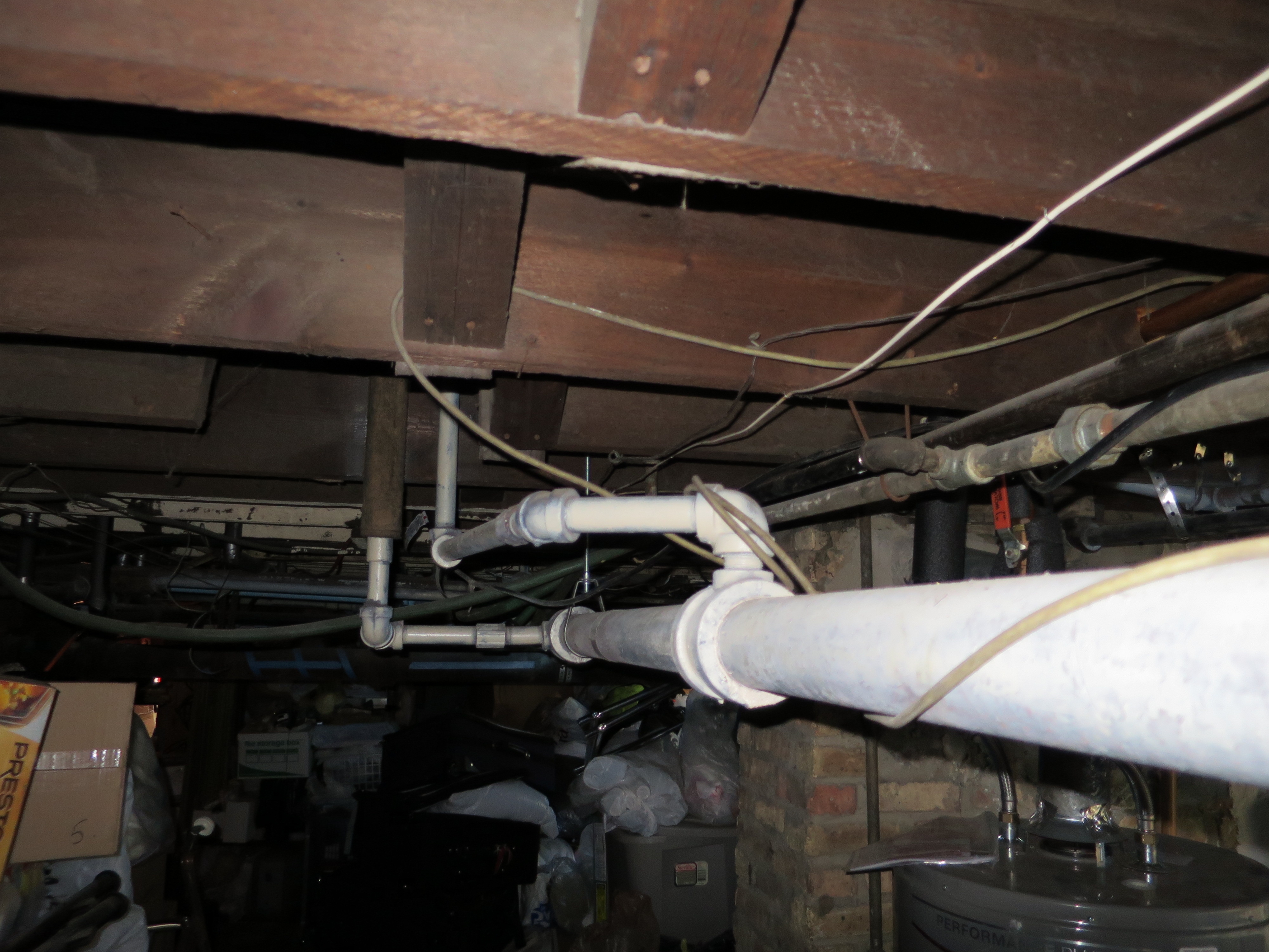
Yes, the layout is accurate in the essentials. The first pic at the top of the thread shows the take-offs for one radiator, the first pipe teeing off the top of the main, the second returning into the side of the main. The number of rads on each zone, as shown in the schematic, is not correct; but I doubt that changes the principle. I had the devil of a time getting the software to accept that piping!
I'm glad to have a figure for the head, at least vv. the near boiler pipes; that gives me a leg up figuring out the head at the pump. By they by, no copper in this system - all iron. I'll come up with a number for the Burkay boiler to complete the picture and give me something to try to force down the throat of the Taco software. Very nice program but it thinks it knows to much. Or maybe it's even right - it claims 5' head for the boiler. Oughta be able to figure it out and make that design correct by spring...
Your thoughts on balancing are interesting. Would mean I may want to go directly to (some) TRV's if I reach the point of fine tuning this system. Guess that would apply regardless of heat source.
Do you know off hand what the head on a 1" TRV is? Or, I guess maybe a better way to look at it is how does the TRV compare with an old radiator valve in way of head? The radiator flow may be very slow. If those 2-1/2" tees for the radiator take-offs are straight tees, and I kinda suspect they are, that means the flow through the radiator piping is effectively gravity flow. The rads heat well (or most of them, when I get the air out) so there s/b hope for the system, I think.
Thanks
Rufusdisclaimer - I'm a plumber, not a heating pro.0 -
Looks like a single pipe counterflow gravity system. We put a mod/con one of these last year with great success. Frank is right -- ODR with constant SLOW circulation is the key. You'll need some time to tweak the ODR curve. If you need zoning, use TRV's, NOT conventional zone valves.
 1
1 -
> single pipe counter flow
Thanks for the info. The tentative plan is better boiler protection and maybe ODR next year. When the weather goes colder next week I'll turn it on w/a 110*F lower limit. According to what I have read, the copper coil Burkay will tolerate that; from November through February it shouldn't sink that low too often. I run the circ constantly, have for many years - the house is drafty enough that once it gets below 40*F, especially w/a breeze, there are frequent "calls".
When a system works decently I try to keep it running as long as it does the job. Running better is better, of course. If I can separate the system and the boiler I can potentially use this boiler for a long time, especially if I can get the mains insulated well. Now that's a challenge.
It seems to me there is a progression here:
1) lower system temps on ODR w/a few TRV's as needed
2) farthest rads struggling, so force the systems temps higher and add more TRV's
The system delta seems to want to be quite large (40*F) which means that the distant rads can be losing out. I have had some issues along those lines in the past. ODR is way simpler to install than TRV's but "working good" is controlled by the farthest rad and that may force the supply temps a lot higher than would normally be expected from ODR. Pipe insulation will help some, but the mains are probably not much of the load and I'm not actually too adverse to heating the basement - somewhat at least.
Or am I missing something here? Way down the road, I or somebody needs to split the system between 1st and 2nd floors and add another boiler. But that's not on the board for a while.
Rufusdisclaimer - I'm a plumber, not a heating pro.0 -
Not sure how it's piped, but if you're keeping the Burkay you want primary-secondary piping with the system pump on SLOW constant circulation and the primary pump controlled by the boiler. If you can, add a 4-way Taco iSeries-R valve to couple/isolate them.
 1
1 -
The taco I series-R 4 way valve Kurt mentioned would eliminate The need for P/S. It was an either or choice. The benefit of the I valve gives ODR also.
This is not a mod/con boiler so low return water temps associated with the full benefit of ODR need to be isolated from the boiler.
I will add while the i series R may seem a bit pricey it offers many benefits.
0 -
Certainly worth a try. The problem we have seen is that if the water is not circulating through the radiators, the boiler will see only the primary loop (which is very, very low head) and can quite easily short-cycle. Keeping a small circ running all the time on the system side will much better represent the system temp to the boiler's internal limit switches.
These systems are quite unusual, even when compared with a traditional gravity hot water system.0 -
The lag time in these systems is huge -- tens of minutes to see a degree or two of change. When there is only one pump and circulation stops, the entire system stagnates. Once the boiler does fire up, the primary loop heats up quickly, but the gravity (radiator) loops are just getting started. I haven't instrumented the system in enough detail to know for certain, but we see over and undershoots that which indicate that something is not working right without that constant circulation.Hatterasguy said:Under which conditions do you have no circulation through the rads (secondary loop) but flow through the boiler loop? Would not both shutdown at the same time (end of call)?
The best solution might well be a large buffer tank connected to the main loop(s) using 3-4" pipes for pure gravity circulation on the system side as originally intended. Pump the boiler in and out of the tank (on opposite sides, aka 4-port) to create maximum isolation.0 -
Is this system worthy of the contortions required to make it provide even heat? I understand the desire to preserve history, but not at the expense of comfort. Would the poster be better off in the long run to separate supplies and returns?0
-
A real education here. Looking back over the posts, I think I need to clarify a couple of points, though.
1) Single pipe counterflow was identified as the likely configuration. Just want to be clear that the system is most definitely a loop (two actually), with the zones returning at the boiler and combining into a one pump into the boiler at that point.
2) @SWEI pointed out correctly the lag on this system is large. 7-10 minutes to see any response on the return temp gauge. It appears to me the delta for the system is around 40*F. I observed 35*F. but it appeared to be rising and I didn't want to make the tenants too uncomfortable that day. So I set the high limit at 190*F to provide an average of 170*F on cold days. In fact I doubt any radiators will see more than about 155*F because of poor insulation on the mains and none on the risers. The house was originally uninsulated and I doubt my father added much, if any.
3) The pump runs constantly. I can't recall my reasoning from 2009 or so when I set it constant on - distribution issues at the far rads.
From the discussion here it looks to me like TRVs will be the most effective way to regulate local temps. Because of the large mains, I doubt they will have much affect on the system head but if enough of them remain closed or only partly open, the system delta should shrink.
> boiler protection
I don't mind expense (or not too much, anyway). But I do like installations to be appropriate, especially if that means significantly less complexity and maintenance. It appears to me a simple 3-port valve on the return at the bypass so it regulates temp into the boiler would do that. EXCEPT - how does the valve know to let the system flow through (no bypass) as long as the boiler it not firing?
Presently there is a 3/4 bypass w/corrugated flex and a butterfly valve. The valve works perfectly but the bypass might as well not be there for all the affect it has on return temps w/the valve wide open. Read zip to two degrees...
Thanks for all this information.
Rufusdisclaimer - I'm a plumber, not a heating pro.0 -
Ah. A problem.
It seems to me that I want the system to flow all the time, regardless of whether the boiler is firing. This will keep temps at the boiler "current" (as much as they get in this system) and it will keep a steady state in the system which should contribute to more even temps and reduced cycle-start affects (like distant or fast-cooling rads not getting as much heat as possible). W/one pump, that means it flows through the boiler if it flows at all. This shouldn't be a problem for the boiler because the condensation issue only occurs during a firing cycle - no fire, no flue gas, no condensation. But it means the regulating valve has to allow system flow through the boiler regardless of temps when the boiler is not firing.
Two Q's:
1) Am I right that there is no large downside to this type of flow?
2) How to achieve this? Clearly the regulating valve (or whatever) needs to know when the boiler is firing and be programmable for the different states (boiler ON and boiler OFF).
Rufusdisclaimer - I'm a plumber, not a heating pro.0 -
-
Right, as long as water is continuously moving through the system side things should work reasonably well. Whether that water goes through the boiler or not is optional (one pump or two.) This is one of those cases where a high efficiency system pump is worth the extra money. If your eventual plan is to install a fire-tube mod/con, I would use two, as the system pump will become the only pump after the upgrade. Don't forget a magnetic dirt separator.0
-
Having not seen the system at hand I can't say for sure. The one we retrofitted a couple years back had almost 200 feet of 3" mains which were still covered in asbestos in the crawlspaces. We fed them using 1" PEX and re-insulated the exposed basement pipes which only took about a day and a half. I'd estimate a re-pipe to the risers would have added about $6k to the job.Paul48 said:Is this system worthy of the contortions required to make it provide even heat? I understand the desire to preserve history, but not at the expense of comfort. Would the poster be better off in the long run to separate supplies and returns?
0 -
Rufus is a plumber. If he split the main loop and re-fed a riser on each radiator with pex, it would make life easier. He could do a reverse-return and it would self-balance, to an extent.0
-
@Paul48
>repipe
That's the Someday job. Been looking at it for 10 years. Involves rezoning into 1st and 2nd floors. Completely change of system dynamics and would need two boilers to really make it worthwhile. Seems to me it might as well all be in PEX. Bit of a job but it could open up the basement considerably. It's a contender along w/raising the horizontal 4" stack into the joists (presently a show stopper for anybody over 5'2"...)
For now the system delivers heat and has, so far as I can see, the potential to do a pretty decent job given boiler protection to reduce temps in spring and fall and maybe ODR. That would let it all run 24/7/365 w/only pump oiling. Mostly. The Danfoss valve looks pretty good except I don't see it available anywhere in 1"; the correct # is 464A. What I find a lot of is the ESBE labeled valves which appear physically larger; that should work, just make layout more difficult. And there's surely a competitor or two out there.
> P/S
That was my original inclination. Have to stare a while and figure what P/S would involve - exactly. To use one system pump I'd have to join the two supplies leaving the boiler (I'm a bit scared of touching the bolted flange holding little cast manifold onto the boiler outlet, but maybe it's doable), insert pump, then split the supplies again for the two zones; after that hooking in the common return would be a breeze. !! Might see how the price of two system pumps compares to that grief when adding up the P/S.
However, a themic valve and a solenoid valve (to bypass the thermic valve when the boiler is off) seems like maybe a reasonable go. That won't give full flow when the boiler is off because the thermic valve will still be open across the boiler. But it should provide at least half normal system flow and probably more - might do the intended job, have to think a bit.
I guess I'll read up on 4-port valves, too. Really don't have a clue where they fit in, but it's feels better to understand the concepts when looking at options.
Thanks for all you interest. Too much thought today. Off to dinner and a life.
Rufusdisclaimer - I'm a plumber, not a heating pro.0 -
For any general interest, the following pics show details this old system piping. Starting above the boiler and the outboard main of zone-1. The zone-1 return has only one rad on it and just runs back to the boiler. Outbound, there are several take-offs stacked together with their returns down stream several feet. The outboard leg is almost level, the return has a steep slope, drops almost 12" back to the boiler - about 20'. Not sure if that slope resulted from heating design or just some kind of piping convenience; don't see anything that says it's not original. Zone-2 appears to be essentially level, though I haven't checked it in detail - it's almost all soffited.
---------------------------------------------------------------------------------------
3 vertical pipes are from L to R: common return; zone-2 supply (bkgrnd ctr); zone-1 supply (behind copper). The 4 large horizontal pipes from L to R: zone-2 return; zone-2 supply; zone-1 return (partly hidden); zone-1 supply (middle R).
------------------------------------------------------------------------------------------
Looking outboard down zone-1 supply. Pipe at the bottom is the zone-1 return.
----------------------------------------------------------------------------------------
Takeoffs from top, returns to side. Main turns left.
------------------------------------------------------------------------------------------
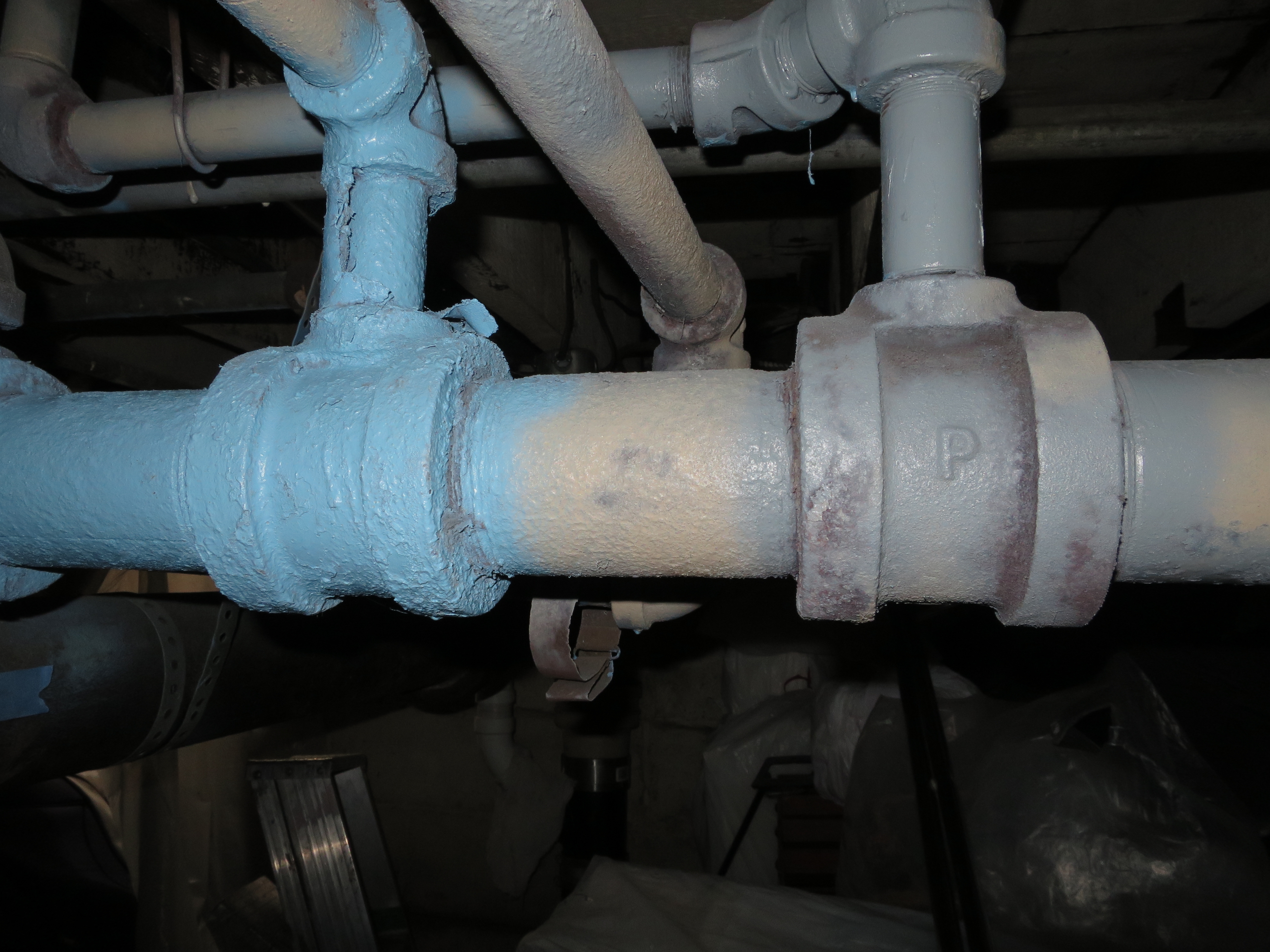
Main enters soffit. 1" on L is return, on R rad takeoff. Main turns left (back to boiler) about 12" into soffit. Straight run back, the 90 over to boiler. One take-off and return on that run.
--------------------------------------------------------------------------------------------disclaimer - I'm a plumber, not a heating pro.0 -
From those reducing 90's, it looks like there was at least one previous retrofit. Insulation will help a lot.1
-
> retrofit
I remember what seemed like a large boiler, box shape, w/the full size pipes connected; would have been oil. The house was built around 1900 and moved to the present location in 1946. I thought my folks converted to gas in the early 60's but I don't have the slightest recollection of an installation in the early 80's - or after, for that matter. So how that Burkay w/the tag saying it was made in 1980 got there is a real mystery to me. I was in CA for 20 years w/not much contact, but normally I'd expect to hear my father's reaction to the price tag even if I were in Australia.
> insulation needed
Yes, that's become unavoidably obvious from firing the boiler last week. Hadn't realized it radiated so much. A friend who is a real estate agent kept bugging us to remove the asbestos (which was in bad shape). A couple years ago I got a hose and bug sprayer and keeping a drenching spray on it, pulled most of the old stuff out. Around here the garbage company will take it if it's double bagged and labeled. Did then, anyway.
The preformed hard pipe insulation (well, _all_ pipe insulation) is priced higher than gold on a per pound basis. I've hung back thinking I must be missing something about that particular market, but about given up. With four more working days here, I'm toying w/the idea of splitting faced fiberglass bats to get about 1"+ thickness; 14-1/2", the width of the fiberglass, is just about the right circumference for that 2-1/2" iron pipe plus 1" insulation. Have to look at the likely R-value. Might not be worth it, even though it should staple together easily using the facing flaps. Always lotsa other stuff to do, anyway. "Real" insulation has to wait for time/money next year.
Cheers
Rufusdisclaimer - I'm a plumber, not a heating pro.0 -
Wow they moved this house to a different location. Interesting how the pipes made the excursion to their new nesting site. Was it moved far?0
-
House was moved about 1/2m i or so. IIRC, all the risers have unions. So the mains may have traveled separately or been redone. I don't have any real documentation on the details of the move. A school was going up and it looks like a contractor bought this and the one next door on spec, moved them and refurbed for sale.
Rufusdisclaimer - I'm a plumber, not a heating pro.1


Categories
- All Categories
- 87.7K THE MAIN WALL
- 3.3K A-C, Heat Pumps & Refrigeration
- 59 Biomass
- 430 Carbon Monoxide Awareness
- 128 Chimneys & Flues
- 2.2K Domestic Hot Water
- 5.9K Gas Heating
- 121 Geothermal
- 170 Indoor-Air Quality
- 3.8K Oil Heating
- 79 Pipe Deterioration
- 1.1K Plumbing
- 6.6K Radiant Heating
- 396 Solar
- 16K Strictly Steam
- 3.5K Thermostats and Controls
- 56 Water Quality
- 51 Industry Classes
- 51 Job Opportunities
- 17 Recall Announcements