Is this 2-pipe buffer tank diagram equivalent to closely spaced Ts?


Regarding the Ts going into the buffer tank, I plan to use a street tee since I can't get any closer than that. Or is there a best practice that suggests I should use a close (or short) nipple and regular T?
Thanks everyone. I'm really learning a ton here.
Comments
-
yes the 2 pipe buffer setup is equivalent to closely spaced tees....because of the generously sized tees and that there really close to the buffer it provides hydraulic separation between the system loop and the boiler loop (very low head loss through tank)... I have done this using close nipples and just regular tees....I would prefer to use the regular tees over the street because sometimes the street part of the fitting is a little smaller than the actual inside diameter of the pipe....using the 2 pipe tank method in my opinion is preferred because it keeps a well stratified tank compared to a mixed one using the 4 pipe method...the Caleffi idronics #17 is a great read on this subject.ASM Mechanical Company
Located in Staten Island NY
Servicing all 5 boroughs of NYC.
347-692-4777
ASMMECHANICALCORP@GMAIL.COM
ASMHVACNYC.COM
https://heatinghelp.com/find-a-contractor/detail/asm-mechanical-company0 -
yes, maybe
")
The key is the sizing of those tees or headers on the tank. Once you have the total flow rate expected in those tees or header piping, select the size based on low velocity in that section of piping.
You can find the piping velocity tables online, here is an example.
Think short, fat, large diameter. There is no harm in oversizing that piping detail.
Bob "hot rod" Rohr
trainer for Caleffi NA
Living the hydronic dream

 3
3 -
Thanks Rod & Paul.
The idronics publications are great reads but somehow I still need some assurances to make sure I'm understanding the concepts correctly.
That chart is helpful, too. I've been doing the math for every different brand & size of pipe.DIY'er ... ripped out a perfectly good forced-air furnace and replaced it with hot water & radiators.0 -
ahh I was asking about this.
does it matter how the tee is positioned, or if positioned as shown which port came from boiler and which went out to system?
Hot rod says its ok too oversize tee, which i think would carry on to the header out from tee to system, In other words if 1 1/4 were a good size to for tee to keep fps [under i think 2fps was the recommendation] then is it ok to stay with that on into the header?
And must the pipe from boiler be less than that, or can the whole thing simply be oversized?
hot rod you mean size the tee according using the total flow on design day?0 -
Generally speaking, bigger is better. Hydro separators are typically 3x the diameter of the pipes that feed them. If you're teeing directly off the tank, I'd use a bullhead tee with the branch sized to the tank port.0
-
Thanks swie my problem is if i recall correctly the buffer has a
1 1/4 port and the boiler a 1 but i used a bushing to come off 1 1/4 and i the system total flow is 7.6 gpm so 1 1/4 is only barely under 2 fps. I suppose i could go back and use a 1" from the boiler but with a bull head wouldnt that make my header undersized. There is a larger buffer with a 1 1/2 port is that what i need to do have the tank port a size larger and can the boiler and system side be the same size smaller.
is this the right chart for threaded pipe?0 -
I'm not a huge fan of bushings to make a size transition, it presents a sharp edge, and encourages turbulence. The flow kinda bangs into a wall.
Here is a slick method to increase or decrease with swage nipples.
The brass 1X1-1/4 is actually from an old Munchkin, they used them right at the boiler.
The galvanized is a resin coated from the petroleum industry,
1-1/4 x 2. All sorts of sizes and materials online for swage nipples.
Use the largest flow rate and size for under 2 fps, better yet under 1 fps, it is usually just 1 pipe size larger to get that flow as slow as possible in the section.
img src="https://us.v-cdn.net/5021738/uploads/editor/o1/2h69poxw6mwq.png" alt="" />Bob "hot rod" Rohr
trainer for Caleffi NA
Living the hydronic dream0 -
Why not install a 1" x 1" x 1-1/4" tee right at the tank?0
-
SWEI said:
Why not install a 1" x 1" x 1-1/4" tee right at the tank?
That would work also, you will need a 1" nipple to reach thru the tank insulation.
The swage nipple gets the increase as quickly as possible, stack tees on the end for take-offs.
Assuming it is an FIP connection at the tank? If it has a nipple welded in the tees are easiest way to increase.Bob "hot rod" Rohr
trainer for Caleffi NA
Living the hydronic dream 1
1 -
The SMART tanks have female fittings on the side for the outer tank. Those would benefit somewhat from a swage nipple depending on the flow. The inner tank has male stainless fittings protruding from the top.0
-
-
Still have yet to install my buffer tank. Just haven't made the time and still not sure how I'm going to tie into my system yet. Any suggestions guys?0
-
Hot rod thanks
i saw your video on the swage nipples thought they were a neat idea. Unfortunately the TT boiler had 1"nipples but the TT indirect required 1 1/4 so i used a 1" female by -1-1/4 male bishing over the boiler nipple and ran 1 1/4 copper. Unfortunately i also made a up a 1/14 header which is just barely under 2 fts because i used an online calculator and changed the flow and pipe size to gpm and inches but didnt catch the output was in meters per second. Im going to change whatever needs changing but space is tight and the buffer is likely going to be a future option in case it becomes needed or necessary in which case i dont want to repipe it all thats why im trying to get a sense of what leeway i have in terms of tee orientation and the relation of the size from all three tee legs.
Swei a bullhead would be nice as a tight conection and the up down orientation would be great guess im just wondering if 1 1/4 from all sides (1.98 ft p s) would also work, since i did the header and from boiler in that size. Im guessing I want that sudden pressure drop by size change.
The better option that might not be good enough is the larger tang has a 1 1/2 port so i could use a 1 1/2 x 1 1/4 x 1 1/4 bull head but do you guys think 1.98 fps on the header would be sufficient with zone valves on design day0 -
swie the smart im using as an indirect and yes it has females i might as well confess for space concerns i used 1 1/4 brass radiator 90 unions hope they were ok i was pretty proud of my solution
so now im wanting to do my ch headers with non P/S, but be prepared if need be to add a buffer and second pump.i could step down the pipe to 1'' after the indirect tees on the boiler or stick with 1 1/4 @ 1.98 fps if thats ok and plan on a buffer with a 1 /12 port, thats the least re work but i dont know if 1.98 fps is sufficient or if its ok to have that all the way from boiler to headers or if the header [s] need to jump up just before the zone valve tees0 -
NJtommy take hotrods advice and read caleffis idronics 17 one thing it warns is dont top into top and bottom of buffers0
-
Hot Rod those are awesome! And pricey.
I'm finding the tank-to-tees transition to be very clunky - the tank size (1-1/4 FIP tank) to the larger tee plus a transition from the tank's black iron. I've change my mind on how to pipe this a half-dozen times and every incarnation was probably just fine; I should stop looking for perfect.
I've settled on FIP TANK -> nipple -> dielectric union -> nipple -> bushing -> tee. Now that I've written that out, I want to change my mind again.
Should I? dang it. FIP TANK -> black nipple -> black bushing -> black tee.... shorter & sweet. Or TANK -> nipple -> bell reducer -> street tee. Still need to transition from black iron at some point.
this never endsDIY'er ... ripped out a perfectly good forced-air furnace and replaced it with hot water & radiators.0 -
I'd skip the dielectric union, for sure. All black fittings would be the least$$ and easy to adjust or modify.Boon said:Hot Rod those are awesome! And pricey.
I'm finding the tank-to-tees transition to be very clunky - the tank size (1-1/4 FIP tank) to the larger tee plus a transition from the tank's black iron. I've change my mind on how to pipe this a half-dozen times and every incarnation was probably just fine; I should stop looking for perfect.
I've settled on FIP TANK -> nipple -> dielectric union -> nipple -> bushing -> tee. Now that I've written that out, I want to change my mind again.
Should I? dang it. FIP TANK -> black nipple -> black bushing -> black tee.... shorter & sweet. Or TANK -> nipple -> bell reducer -> street tee. Still need to transition from black iron at some point.
this never ends
Bob "hot rod" Rohr
trainer for Caleffi NA
Living the hydronic dream1 -
keyote said:
NJtommy take hotrods advice and read caleffis idronics 17 one thing it warns is dont top into top and bottom of buffers
You can drop in the top of a tank, just build or buy a sparge, ( not to be confused withe swage nipple, basically you want the flow to spread across the top and bottom, not straight in flow which breaks up the stratification.
I've seen these nipples shipped with tanks intended for chilled water applications to, again, drive that stratification. They look like water heater dip tubes, with the plastic end fused closed and slots around the outside.
It's easy to build them with a double tapped bushing and a copper dip tube with holes or slots.
Perfection Co used to offer these tubes, I don't see them around anymore after that dip tube class action suit a few years back where the tubes came apart.
Bob "hot rod" Rohr
trainer for Caleffi NA
Living the hydronic dream0 -
I found SS unions and fittings to be about the same as black but i always choose brass over dielectrics they just seem to always do the opposite of what theyre supposed while i never saw a brass between steel and copper rot out, and brass can usually be found as a thread to sweat transition or a thread to sweat copper can be put into them, try not to sweat after you thread you can get leaky threads occasionally
I liked the brass radiator elbows with integral union then screwed in a copper thread to sweat on the indirect it was $15 at plumbing supply in 1 1/40 -
So just marry the black iron to copper and let them fight it out?DIY'er ... ripped out a perfectly good forced-air furnace and replaced it with hot water & radiators.0
-
Yep, just keep oxygen out of the system and no worry about corrosion, or damaging, fighting, reaction between the dissimilar metals. Copper to steel or iron is common in hydronics, start with a brass tee or nipple for extra piece of mind.Boon said:So just marry the black iron to copper and let them fight it out?
A squirt of Rhomar hydronic conditioner is a big help to hydronic systems also
Bob "hot rod" Rohr
trainer for Caleffi NA
Living the hydronic dream1 -
hotrod im kind of shocked i understand oxygen needs to be present and copper and stainless is done and dielectrics are not all that is supposed but i never heard anyone say to not at least use brass between black and copper. have i really been overly cautious all these years0
-
Keep the oxygen out and the pH up and they will last decades even when directly connected.
 1
1 -
Many, many decades with closed systems.Steve Minnich0
-
keyote said:
hotrod im kind of shocked i understand oxygen needs to be present and copper and stainless is done and dielectrics are not all that is supposed but i never heard anyone say to not at least use brass between black and copper. have i really been overly cautious all these years
I'm reluctant to add anymore to your plate
A little water quality info is a must for healthy, long lasting hydronics.
True the lack of O2 is part of the potential for corrosion, important is the conductivity of the water. The O2 in the fill water is consumed quickly by oxidizing any steel in the system, like pump bodies and expansion tanks, once the process is complete you should be O2 free. Unless more is getting in with fill or leaks.
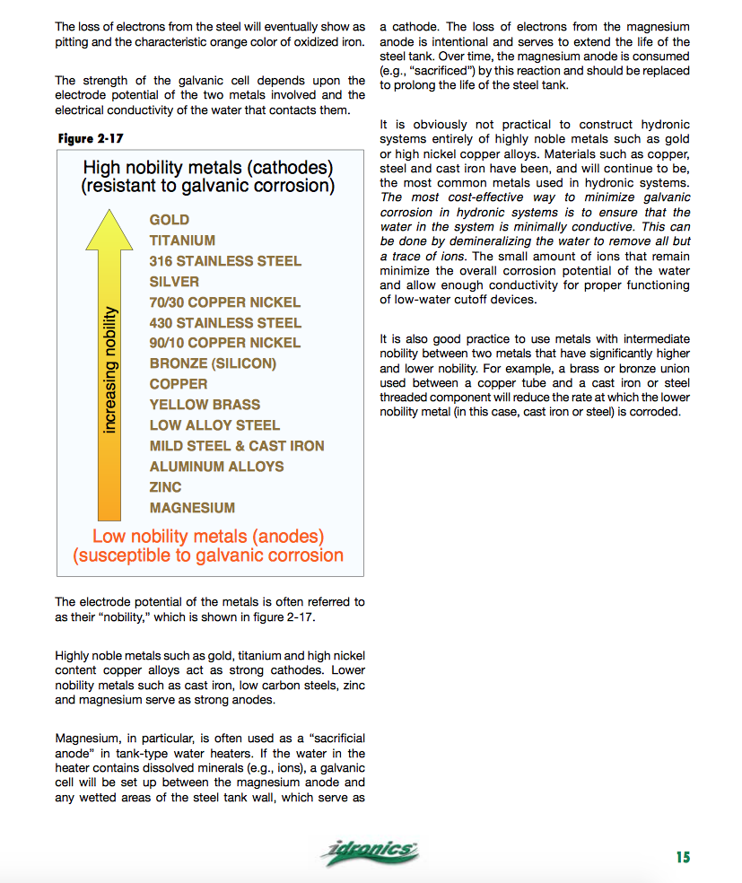
The higher the TDS of your water, the greater the potential for galvanic corrosion, strip the minerals "salts" from the water and that potential drop to near zero.
A simple TDS meter reads the conductivity of your fill water, an ohm meter works in a pinch The more "stuff" in the fluid, the higher the conductivity.
Strip all those colored dots, seen on the Idronics 18 cover shot from the fluid.
Copper and steel are not all that far apart on the scale, no harm in introducing brass in the middle, it should not be required in a sealed, good fluid quality system, millions of those copper to steel and iron connections out there
O Bob "hot rod" Rohr
trainer for Caleffi NA
Living the hydronic dream0 -
nyc has pretty good water ill worry less now. conventional wisdom wrong again.0
-
"Pretty good water" can have a lower than optimal pH. Check it.
 1
1 -
Excellent drinking water in NYC and LI, some of the best in thekeyote said:nyc has pretty good water ill worry less now. conventional wisdom wrong again.
nation.
Here is what the various boiler manufacturers require to assure warranty. Bob "hot rod" Rohr
trainer for Caleffi NA
Living the hydronic dream0


Categories
- All Categories
- 87.7K THE MAIN WALL
- 3.3K A-C, Heat Pumps & Refrigeration
- 59 Biomass
- 430 Carbon Monoxide Awareness
- 129 Chimneys & Flues
- 2.2K Domestic Hot Water
- 5.9K Gas Heating
- 121 Geothermal
- 170 Indoor-Air Quality
- 3.8K Oil Heating
- 79 Pipe Deterioration
- 1.1K Plumbing
- 6.6K Radiant Heating
- 396 Solar
- 16K Strictly Steam
- 3.5K Thermostats and Controls
- 56 Water Quality
- 51 Industry Classes
- 51 Job Opportunities
- 17 Recall Announcements