The Hidden Hydronic Problem Nobody Checks: Water Velocity
Comments
-
Does that pre-1930 handbook you showed above say anything about GPM or flow velocity? Or even BTU/hr and temperature delta? Because if you know two you can derive the rest.
In a post above I estimated that the pressure difference between two 20' columns, one at 180F and the other at 160F, would be 0.06 PSI. Plugging into a pressure drop calculator, I get 6.5 GPM for a 0.06 PSI drop over 100' of 2" galvanized pipe. Which works out to 65,000 BTU/hr. That's a flow velocity of about 2.5 feet per second. I'd be curious to see what the handbook said for the capacity of 2" pipe.
Note that it's somewhat self-balancing. Let's say you have more than 100 feet of pipe. The water coming out of the radiator is actually colder, say 140F. So it's denser, and the pressure differential is higher, so you get more flow than you would at 160F, which partially makes up for the longer pipe. Overall you get less heat — the average radiator temperature is lower — but only a bit less.
0 -
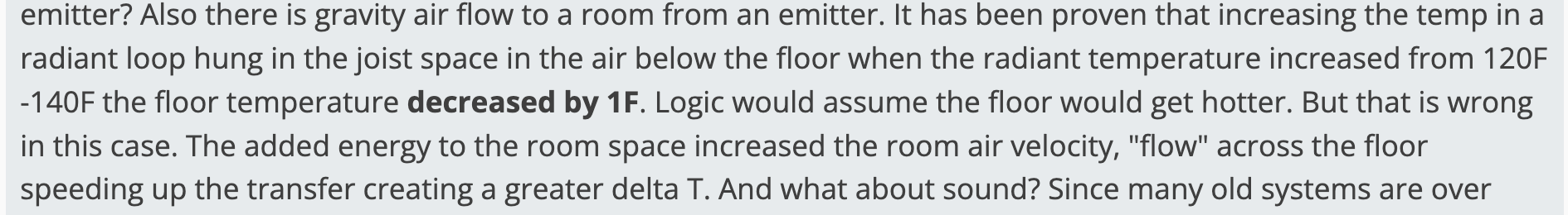
Hot topic? Too much to read and too little time. these are just 2 factors of many involved in assimilating knowledge. Same with heat transfer. We considered flow at the main, the loop, but what about the loops in the emitter? Also there is gravity air flow to a room from an emitter. It has been proven that increasing the temp in a radiant loop hung in the joist space in the air below the floor when the radiant temperature increased from 120F -140F the floor temperature decreased by 1F. Logic would assume the floor would get hotter. But that is wrong in this case. The added energy to the room space increased the room air velocity, "flow" across the floor speeding up the transfer creating a greater delta T. And what about sound? Since many old systems are over sized its rare to have a problem with replacement stuff, but a system properly designed using a B&G 100 1725 rpm circulator was replaced with a boiler packaged with a 3450 RPM pump, the heat was fine but now a hum noise emanated from the pipes. Solution: change pump to 1725 RPM. Problem solved. I was caught wrongly accepting the boiler as is then checking this detail. Easy to determine, surprising to find. Beware the manufactures selling choices will not always match the owners or contractors buying choices, we have to choose wisely. To be great in this business you need to be a detective and that requires a whole lot of other skills. Is it me or is it getting warmer in here?😉 Great stuff from all contributors!
0 -

This doesn't seem to jive with any output charts from the radiant manufacturers.
In all cases a warmer emitter, including the floor, should increase btu/ area output.
Charts from the Uponor Design Manual
 Bob "hot rod" Rohr
trainer for Caleffi NA
Living the hydronic dream1 -
@hot_rod "In all cases a warmer emitter, including the floor, should increase btu/ area output."
Yep. And I still fail to see any scenario where an increased flow doesn't lead to a warmer emitter.
1 -
Hi, Hot Rod, The emitter tubing is warmer 140F or more. The floor is just a pass through. Its surface temp in the room is affected by the increased room air velocity created by the increased thermal supply. Not unlike how an open window affects air flow across a floor. The output is greater, its evidence of the greater temperature split. Its just an effect tested and observed by Ultra-FIn. The effect of too high a temp in flooring causing damage is real. But what I built in my home was a way of providing for outdoor temp reset controlled boiler water with different emitters. Too high direct floor contact emitter is not good without tempering control. I use both a hydronic air coil, for my Forced air heat units, and using that same temp water with Ultra-FIn in my floor joist space. Essentially the boiler water travels to a tube emitter to joist air space to, through the floor, to the room air, to the outside is the pathway of the heat supplied. It is how I make old boilers with radiators running at 170F heat a radiant floor without mixing valves. For zone control I add a T-stat controlled zone valve. No need for "in room emitter" at all.
I have done all forms of heat and systems except nuclear. There is nothing more amazing to me than the laws of physics and nature. While my statement on floor temp decreased it is not always the case. Depends on certain . See attached.
0 -
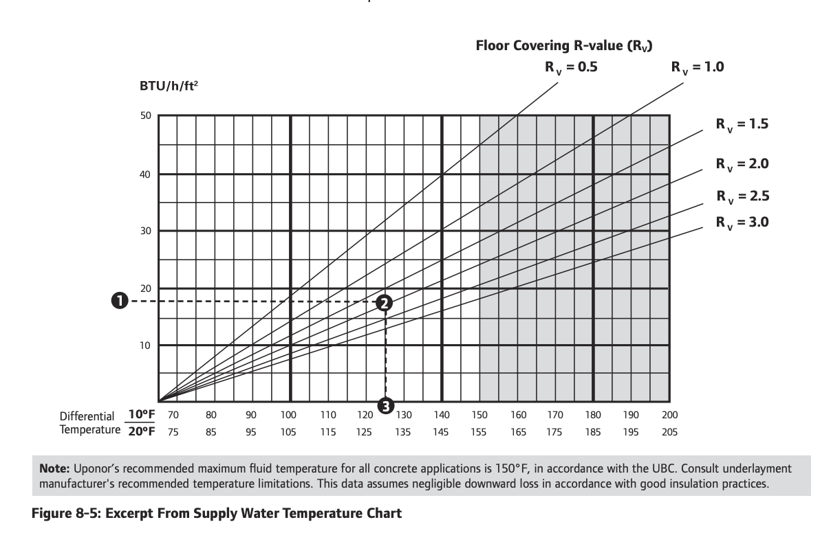
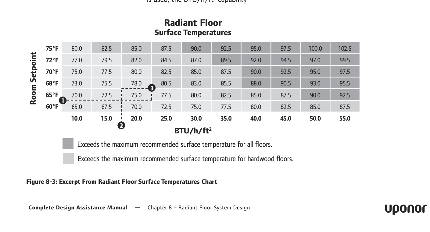
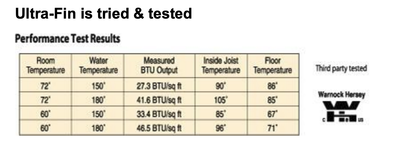
According to that document, they claim with a room temperature of 72F, with water temperature of 150F you get an output of 27.3 BTU/hr/SF and a floor temperature of 86F, while with a water temperature of 180F you get an output of 41.6 BTU/hr/SF and a floor temperature of 85F.
Hmm.
0 -
There should not be much air movement with just a radiant panel heating system.
If you add convectors like fin tube of forced convection like an air handler, the heat dynamics change.
This was always the Uponor selling point for radiant, very little temperature stratification or air movement.
Lots of opinions on radiant panel output. The 2 btu/ degree differeance seems to be commoly accepted. See Uponor explanation at bottom.
Not sure how UF gets 45 btu/ sq ft with an 11° differance?? I come up with 71-60= 11 X 2 = 22 btu/ sq ft?
Does it matter how the floor surface is warmed? Plates, staple up bare tube, suspended pex, suspended pex with UF? The math doesn't differentiate the heat transfer mechanism. How does UF change that equasion? The only air movement it adds is in the joist bay, under the floor. Unless vents are cut into the floor to allow convection currents into the space.
I've used UF on several jobs and it needed supplemental in high load rooms just as plates or slab radiant does. To me that 25- 27 btu/ sq ft is reasonable. Beyond that you need a lower room temperature. Think snowmely where 200 btu/ sq ft is possible, it's the ambient driving that high output.
 Bob "hot rod" Rohr
trainer for Caleffi NA
Living the hydronic dream1 -
Bob, Like all applications even identical houses are different with different orientation.
I would be in error to assume all is equal everywhere. Every training I did had specific and general realizations and I believe all solutions will not work in all applications.
Suffice to say an open floor plan with zoned areas is not the same as a single area with one zone. The variables alone cannot be all accounted for for each and every btu, or degree day. Just like in all mechanical things there is a sweet spot for perfect operation and then there are the perimeters of lessor performance.
I was amazed when I learned there is a thin layer of air on the outside of a building wall that has a insulation value. I am still learning. Its true, the more we learn the dumber we should realize what we really don't know.
A thing meant to maintain is different than a thing starting from a stop. Uphill travel different than down.
I truly have not been able to see many situations where identical things perform the same in identical circumstances except on an assembly line.
The solving the mystery, the thrill of a design that works without tweaking, the perfect job is the goal. Rarely in the field is a thing installed perfect. It's what keeps us busy fixing, figuring and learning what to do and not to do that is the real challenge to the nut bolt assembly of anything. I was bored hanging my second storm door. I knew than I had to be challenged with the unknown to be happy in a career.
When I designed from scratch with the good teaching I was taught, I succeeded. When I repair, replace or make it up as I go I rely on the principles I learned. But I am not too rigid to think outside the box. And sometime thats what works best. So keep training we need it. Thanks. Lance
0 -
I agree each application is different and has different requirements.
Basic laws of thermodynamics hot goes to cold, the rate of exchange is based on the temperature difference
So increasing the SWT from 120-140 would seem to increase the floor surface, correct?
I’m not sure how you measured that 1 degree floor temperature drop. Seems 1 degree could be a measurement tolerance. Any change to the distribution requires you wait until the system reaches thermal equilibrium to confirm the numbers. That condition is when supply and return temperatures have stabilized, neither moving up or down. That can take some time with a radiant floor system, even the low mass have thermal lag.
Without knowing how the UF was tested, be hard to comment on their output claims. Do you have that info?
Used to be fin tube manufacturers all sent their products to IBR for performance certification. All were tested in the same chamber under identical conditions. So typical 2-1/4 fin tube all performed pretty much the same. Most brands printed the IBR shield on their packaging. Proof of certified testing.
One of the high output fin tube brands decided to do their own testing. All write up of the test chamber showed they had two fans running in the test room.
Obviously that increases the air movement across the fin so output jumps. So you can get most any result you want by tweaking the test procedure.
That 2 btu/ degree difference seems to be the number most all the industry uses. Lab testing at KSU years ago, multiple FEA analysis all seem to agree that is a realistic number.
Bob "hot rod" Rohr
trainer for Caleffi NA
Living the hydronic dream0 -
All I know is UltraFIn was tested by Warnock Hersey.
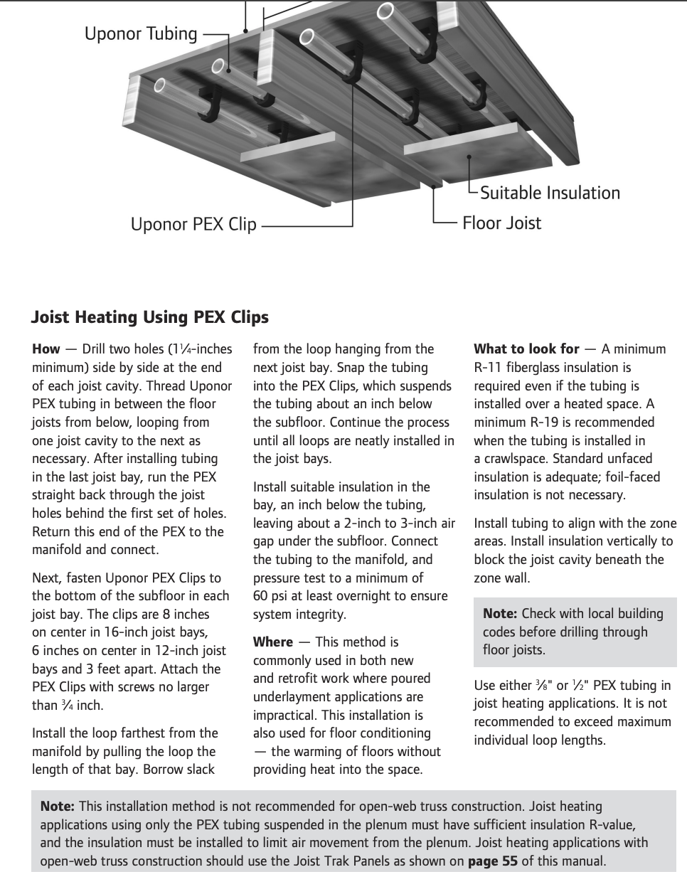
In the example an increase of joist air from 90 to 105 caused a floor temp drop of 1 F. and water temps when the room air was at 72F. I believe the room air temperature is a factor. We have two variable changing in the results. In a colder room 60F when temps were higher both joist air and floor temp went up. This makes sense as air circulation being different will vary its conduction rates. The key here is to understand that there is a tube with a fin attached to the emitter, trapped in an air space between joists creating a convection current in the joist space to another convection current in a room. The only thing between the spaces is the insulating floor. Learning of convection currents in small bubble materials, until they get to a very small micro space those convections currents still transmit the heat often faster than radiant waves. Nevertheless, it would be fascinating doing tests monitoring all the conditions with better controlled conditions. I only believe it because of Warnock Hersey. https://www.intertek.com/product-certification-marks/wh/
0 -
How are they arriving at the BTU/sq. ft output. Measured? Calculated? Imagined?
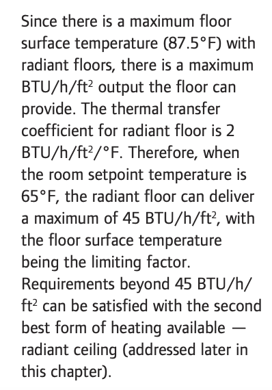
Industry standard shows 87° floor surface - 65° room = 22 X 2 = 44 BTU/ sq ft. 87° is a really hot floor to stand on. Maybe with insulated shoes in a cold shop?
How do they get 46 BTU with 71- 60? (11X 2= 22 BTU/ sq ft)
Air currents in the room do not increase the floor surface temperature or ∆? Ambient temperature is being measured by the wall thermostat.
I only believe it because of Warnock Hersey. https://www.intertek.com/product-certification-marks/wh/
It's good to question authority sometimes :)
Have you ever done a room or job with a 46 btu/ sq ft load? With just UF? Would you?
Bob "hot rod" Rohr
trainer for Caleffi NA
Living the hydronic dream1 -
I usually give great deference to manufacturers' published numbers, but this just strains credibility.
What I've always heard is that the heat output of a heated floor is completely determined by the temperature difference between the surface of the floor and the room air. How can what's happening on the other side of the floor affect what happens on the room side?
0 -
air is not a great conductor of heat energy. Water transfers something like 3500 times air.
Conduction, from water to tube wall to plate and to the floor, makes sense to me.
Would a strip of find tube be an option to a strip of aluminum clamped on pex every few feet?
No doubt UF can transfer heat energy, but the output numbers seem a but optimistic, to me.
Bob "hot rod" Rohr
trainer for Caleffi NA
Living the hydronic dream0 -
Still waiting on the alternate explanation for why:
1- the boiler was no longer leaking and kettling, and
2- water was no longer short-circuiting through the radiators.
The answer was slowing the flow and redistributing it through the boiler, period. I would not have written the articles were that not true.
Some younger folks on here likely don't understand the concept of "dwell". When servicing a vintage engine using breaker-point ignition, the points (which are basically a switch) had to stay closed long enough for the electrical field to build up in the ignition coil, so that when the points opened and the field collapsed, it would produce a good hot spark. This was the dwell period, and could be varied by adjusting the gap of the points.
The same principle applies here. If the water is moving too fast through a boiler or radiator, it doesn't spend enough time there to either absorb heat from the boiler or transfer it to the radiator. That old Spencer was an extreme example.
I've done the same on countless systems and they always heat faster and produce better comfort. Plus, a smaller circ uses less power. That's a win-win if there ever was one.
Baltimore, MD, USA
Steam, Vapor & Hot-Water Heating Specialists
Oil & Gas Burner Service
Consulting0 -
Well we will have to agree to disagree on this, probably to the end of time :)
I think what many troubleshooter miss is they assume measuring ∆ T across a boiler or emitter tells the story.
I'd guess many if not most techs have a means to measure temperature with their VOM or separate temperature gauges of some sort. So the ∆ is not hard to determine.
BUT you need to know flow rate also 500 X flow X delta T. If you don't know flow to plug into the formula, you cannot assure heat is being transported at any rate.
The boiler and heat emitters are both considered heat exchangers, so concepts are the same.
I doubt many tech have a meters of accessible balance valves with TP ports and a ∆P meter and pump curve on hand, to check and assure flow in a system?
I hope Ray address that since he opened this velocity topic, he should not, can not leave the crowd hanging🤔
Share the knowledge and tools to "know" the flowrate and, complete the formula, finish the quest.
For more on heat transfer for newbies or oldbies, read this.
 Bob "hot rod" Rohr
trainer for Caleffi NA
Living the hydronic dream1 -
One thing I find strange about the examples / citations that @DCContrarian and @hot_rod explore in this thread is that they imply that your heat source increases its output as you elect to use a faster pump speed. The extra BTU's in @DCContrarian's example and @hot_rod's pasted picture had to come from somewhere, but in the problem described at the top of this thread, the boiler is (presumably?) emitting a fixed output. How could this boiler supply more btu's just because the circulator sped up? What am I missing? Even if you removed the circulator, you'd get heat delivery, at exactly the boiler's output, via thermosiphon, right?
In my mental model of how systems like this work, pumping speeds can affect the heat output of a given radiator as long as there is more than one emitter in the circuit. If one radiator's output increases due to a change in pumping speed, one or more radiators in that circuit must necessarily emit less. That is, pumping speeds can probably affect balance, but its hard to imagine that they can affect total heat delivery. However, I'm neither a heating contractor nor an engineer so I might be missing some nuance here.
0 -
The main difference between gravity and forced circulation is that the former is dependent on the water temperature, whereas the circulator makes the flow rate independent of the water temperature. So we get full circulation even on mild days, where some gravity systems don't circulate well at the ends of the system.
Baltimore, MD, USA
Steam, Vapor & Hot-Water Heating Specialists
Oil & Gas Burner Service
Consulting0 -
it is explained in the formula to define the change
500 x flow in gpm x temperature difference.
Just change the gpm, same delta, same 500 factor
500 x 5 x 20=50,000
Now bump to 6 gpm
500 X 6 X 20=60,000 60,000
But the cost is the extra pumping power to get the higher transfer
Did you download and read the Idronics 23 that I attached?
It covers the theory, concepts, formulas and actual examples
It is best to start at square one, page 1 for a complete understanding of jumping into the middle of hydronics 101 can confuse the student.
Suppose your car engine is spinning at 4500 rpm. In a selected gear you travel X miles in an hour
Increase the rpm to 5500 rpm and you cover more miles
And the same effect where resistance increases at higher road speed
Bob "hot rod" Rohr
trainer for Caleffi NA
Living the hydronic dream0 -
In my examples I'm talking about radiator output.
Typically in a boiler when the burner is running the burner is adding heat to the water faster than the radiation is taking it away. The boiler cycles on and off, with the temperature rising when the burner is on and then falling when it is off. If the output of the radiators increases, the rate at which the water temperature rises will slow.
You have to keep in mind that if you have a functioning thermostat, the output of the radiators is going to be determined by the heating load of the house. If the output of the radiators increases, the thermostat is going to be satisfied faster and the on time of the radiators is going to be shorter. If the heating load doesn't change, the on time of the boiler ultimately doesn't change.
0 -
Hot Rod, when all the science is accepted and an unexpected result appears I make two conjectures, A) original science is wrong or incomplete, or B) the test is flawed, incomplete or wrong conclusions are made.
I have seen the similar results achieved by measuring only two things when the unexpected occurs. Upon further inspection the "why questions" explained it all.
Are all the factors discovered, all variables accounted for? Fluid flow fluctuation changes can behave differently at different speeds with the same shapes. Velocity of air can turn a corner better at slower velocity. The effect is: I lowered the air speed to increase the airflow in the branch. The variables are more than 2. We just talk about the two because if unexpected, it begs more questions to be asked/answered. The joist radiant model is more complex than a direct water in a tube to a floor emitter to the air.
Ultra-fin system creates a tube to plate emitter and combines it into a Joist space. This creates the joist space emitter into a hot air convector with a warm stovetop like surface. This Joist space floor emitter has its heat pulled into the room air. The Room air has its heat pulled outside to a lower temperature. As they say, question the authority. Can we predict a single emitter's output transferring through another emitter's output without showing the degree by degree variations between the two transfer rates? Suffice to say, testing showed a drop in floor temp when only certain conditions were measured.
Joist space achieved a greater temperature over time than the room space. Joist space is quickly affected by BTU input. Height and distance are different for both air spaces and the convection air current's shape and velocity. Room air circulating by gravity at certain temps creates its velocity that controls the pull of BTU's from the floor surface. Assuming the boiler temp rises and CFM remains static, the BTU content per cfm will increase the emitter output. The higher the temp the greater the joist space temp until it equalizes. Now this is based on a surface area slightly less than the emitter above it. Each joist takes up 1.5" 10 joists equals 15" a small factor but its there. The floor emitter of the room is unrated and untested. So how it behaves depends on the heat loss and gravity air flow velocity across the floor surface of the room. How is it to be rated?
In the room set at 72F, the tube water temp is 150F the joist space is at 90F and the floor at 86F. Only changing the water temp to 180F changed the joist space to 105F resulting in a floor temp of 85F. 1 degree less. In the next set of results we start with a room temp of 60F and keep the water temp at 180F we see different results. But without the why and how answered. When loads change and demand changes the dynamics of joist temp space changes. But Why is not answered because the Ultra-fin test was to show how floor temp would be safe for the floor. And while it 72F temp control would be a floor too warm, course my dog would disagree, we would probably actually keep a lower room temp setting because the heat is where we want it. on the floor. Set the stat at 60-65 and with the floor warm the warm comfort is there. But lets be real. Who is comfortable at what temp with what type system. We have 90F air from a heat pump and we feel cold, but we have 70F or less from radiant and we feel, well warm, or shall I say it is a variable choice between the occupants. We can argue the finer points but it usually comes down the clients sensible and latent heat control and their personal choices.
In electrical design is all math. I was told even if a circuit is proven by math it may not work as expected. I asked why? and was told that electricity does not always obey the math of ohms law. Another mystery that teaches a principle; Not all that is unknown will be known. I am done with this thread. Right or wrong its is good to learn both ways.
0 -
I think however you spin it, the UF is heating the joist space, period. If that space is sealed from the living space with framing, floor covering, etc, as most floors are, how does that heated joist bay air communicate with the air space of the room?
So basically the warm air in the joist cavity heats the floor above. You could stick a few hair dryers into the space i suppose and warm the floor :)
I have seen fin tube installed in joist bays for decades, nothing special about UF other that it clips easily onto pex.
What is missing from some of the radiant products brought to market over the years, is actual peer review, FEA modeling, real world data collection by an independent source. I suspect WH did some testing in a hot/ cold chamber not at an actual installation??
You may remember the bubble foil claims of 1/2" thickness outperforming 2" extruded foam. Questionable claims on the nob foam panels.
I don't question UF works, heats many homes just fine. I did several but had supplemental transfer plates in the high load areas, and I did two runs of pex in every joist bay, tube was cheap.
There is science (evidence based pursuit of knowledge) and there are the laws of thermodynamics, one is negotiable.
And " The stars may lie but the numbers never do" Mary Chapin Carpenter :)
The concept of "cold 70" or forced air vs radiant panel heat, is well known.
MRT is the mean radiant temperature a weighed based average. Radiant energy warms everything in it's "sight" that is the difference between FA and radiantly heated spaces, so ambient can be reduced in many cases with radiant, because the objects in the room are mini radiators .
Your dog already knows this. They generally move constantly from warm surfaces to cooler to regulate their body temperature.
Bob "hot rod" Rohr
trainer for Caleffi NA
Living the hydronic dream0 -
@Steamhead : "Still waiting on the alternate explanation for why:1- the boiler was no longer leaking and kettling."
I'm going to answer the question with a question. When there is zero flow of water through a boiler, there is no heat being removed from the boiler. Once there is some flow some heat is being removed, and as the flow increases the amount of heat removed increases. If I understand your contention correctly, at some flow the amount of heat removed peaks; beyond that point increasing the flow results in a reduction of the heat removed. And operating the boiler at the reduced level of heat removal leads to leaking and kettling.
My question is, even if all that is true, why is operating the boiler at reduced heat removal a problem at high flow when operating at the same heat removal at low flow isn't?
As a hypothetical, imagine a boiler that can supply 100,000 BTU/hr when the flow is 10 GPM, but at flows greater than that it supplies less. Further imagine that at 20 GPM it supplies 80,000 BTU/hr, and that flow is problematic. There is going to be some flow between zero and 10 GPM where it's also going to supply 80,000 BTU/hr, let's say it's 8 GPM. Why is 20 GPM a problem when 8 GPM isn't?
0 -
I really don't know at this point, except to conclude that the water was moving way too fast.
And the water was shooting through the bottom of the rads and going back down the returns so fast, the rads didn't heat well. The risers were exposed on the first floor so it was a simple matter to put my hands on both risers, feel the heat coming up the flow riser and feel it coming down the return several seconds later. I didn't have an infrared camera back then.
Slowing the flow from 115 to 45 GPM and correcting the flow distribution through the boiler solved both problems.
Baltimore, MD, USA
Steam, Vapor & Hot-Water Heating Specialists
Oil & Gas Burner Service
Consulting0 -
The article cited earlier says that for a conversion system, 45 GPM would be suitable for 288,000 BTU/hr. A system that size is going to have a lot of radiators. A gravity system isn't going to have zone valves, to the extent it's balanced it's going to be from trying to match radiators to the load of the room they're in, and by using balancing valves on radiators that produce too much.
Going to a circulator is going to throw the balance all out of whack. The higher the flow, the more that happens.
0 -
Which is why we want to keep the flow rate down to about where it would be with gravity circulation if the boiler was at or near full temperature.
In gravity circulation, the water temperature difference between flow and return creates the "motive head" that makes the water move. With forced circulation, the circ creates it. But once the motive head is established, the system then circulates the water pretty much by itself. Its resistance to flow is that low.
Baltimore, MD, USA
Steam, Vapor & Hot-Water Heating Specialists
Oil & Gas Burner Service
Consulting0 -
Way back on the previous page I talked about how flow affects an individual radiator. To refresh your memory, this graph was the summation:
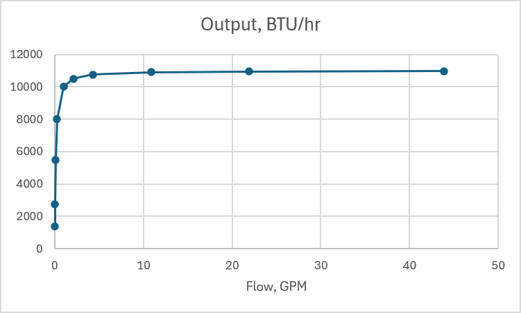
This was a hypothetical radiator that produced 10,000 BTU/hr at 1 GPM with incoming water at 180F and leaving water at 160F.
Imagine you have a gravity system, with two identical radiators of this type, plumbed in parallel. One was plumbed with 2" pipe and delivers the stipulated 10,000 BTU/hr and 1 GPM. The other one is in a lower load room and was plumbed with 3/4" pipe to reduce the flow. Under the same pressure, 3/4" pipe will deliver about 7-8% of the flow of 2" pipe, so the second radiator is getting 0.07 GPM. Using the calculations from my earlier thread, that radiator will produce about 4,000 BTU/hr. And in our hypothetical house the heating load of the second room is 40% of the load of the first room, and everyone is happy.
Now imagine you install a circulator and increase the flow in the 2" pipe to 10 GPM and 0.08 GPM in the 3/4" pipe. At 10 GPM, the radiator on the 2" pipe is going to produce about 10,800 BTU/hr, and at 0.8 GPM the radiator on the 3/4" pipe is going to produce about 9,000 BTU/hr. All of a sudden the radiator in the second room is producing 90% of the heat in the first room, not 40%.
If the thermostat is in the first room, the second room will overheat. If the thermostat is in the second room, the first room is going to be cold — it's getting less than half of the heat it needs. But by all appearances, everything is working. In fact, the return water is quite hot — it's going to be about 176F. But the first room isn't getting enough heat — not because the radiator isn't putting out heat, but because it's not on enough of the time.
Slowing down the flow will make this system work properly again.
0 -
if the larger room in fact needs 10,000 btu at design condition, slowing flow will reduce the output. So the solution is to balance down the larger radiator.
Assuming you need to move 10 gpm, 100,000 btu/hr throughout the entire system?
It's a coarse scale but how does that radiator output 2000- 6000 with 0 gpm flow? Seems like a lot of vertical on that curve?
With the circ added why wouldn't the smaller radiator get 2,3 or 4 gpm? 3/4" can carry that gpm easily. Why only .8 gpm?
Bob "hot rod" Rohr
trainer for Caleffi NA
Living the hydronic dream0 -
I'm still confused by @DCContrarian's example. Suppose these two radiators were all of the emitters attached to a single stage boiler with 14,000 btu/hr output, and they were installed in a space with design day heat loss of 14,000 btu/hr. Further, suppose it is design day conditions outside, and we've set the thermostat to some temperature far beyond 70F. In this example, if you add a circulator, somehow the boiler produces an additional 4,800 btu/hr. Where do those btus come from?
0 -
In that case, the same 14,000 BTU/hr would still be available. But instead of being split 10,000/4,000, it would be split 7400/6600.[Striking my original answer]. If the boiler is only capable of 14,000 BTU/hr that's all the radiators are going to put out. What will happen is the boiler won't be able to maintain 180F water temperature, the water temperature will fall until the output of the radiators matches the output of the boiler.
The flow will still be 10.8 GPM, 10 GPM through the first radiator and 0.8 GPM through the second. The water temperature would be about 145F. The portion of the heat produced by each radiator would stay roughly the same, with the first radiator producing 7300 BTU/hr and the second producing 6600.
0 -
if the larger room in fact needs 10,000 btu at design condition, slowing flow will reduce the output. So the solution is to balance down the larger radiator.
In my example the radiators are the same, the piping is different. But yeah, the radiator in the lower load room needs a lower flow. The original designers did this with smaller pipe.
Assuming you need to move 10 gpm, 100,000 btu/hr throughout the entire system?
No, the assumption is someone installed a pump into an existing system that's moving 10 GPM. This is a contrived example of somebody over-pumping a converted gravity system, they only need 14,000 BTU/hr.
It's a coarse scale but how does that radiator output 2000- 6000 with 0 gpm flow? Seems like a lot of vertical on that curve?
It's not 0 GPM, it's 0.07 GPM. At that flow, the water will exit the radiator at room temperature, 70F. If it's supplied at 180F, that's a drop of 110F. The heat output is going to be 110*0.07*500= 3850 BTU/hr.
With the circ added why wouldn't the smaller radiator get 2,3 or 4 gpm? 3/4" can carry that gpm easily. Why only .8 gpm?
If two pipes are in parallel they have the same pressure drop. If a 3/4" pipe and a 2" pipe have the same pressure drop the 3/4" pipe will have 7% to 8% of the flow of the 2" pipe. I got that by looking at the numbers on these charts: https://www.engineeringtoolbox.com/pressure-loss-steel-pipes-d_307.html
So if a pump is installed that gives 10 GPM through the 2" pipe will have a pressure drop of about 0.1 PSI per hundred feet, according to that chart. (It's 0.095 PSI at 9.5 GPM). Looking at the 3/4" chart, at 0.103 PSI per hundred feet the flow is 0.79 GPM. So round off to 0.8 GPM.
0 -
actually the radiators dictate the boilers operating condition, not vice versa.
Boilers have safety devices, high limits, to prevent over temperature conditions,
If the emitters can overpower the boiler, a low temperature protection should be added.
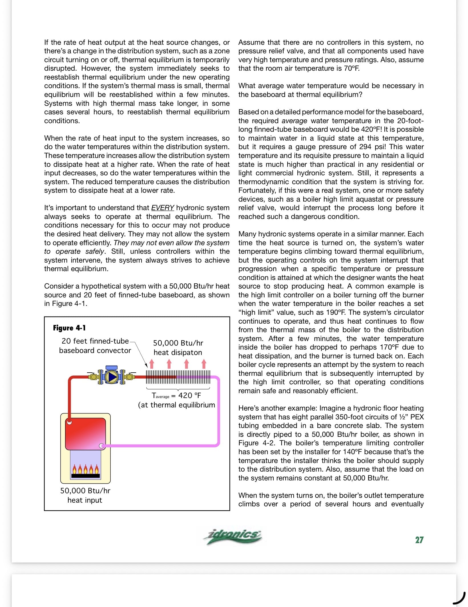
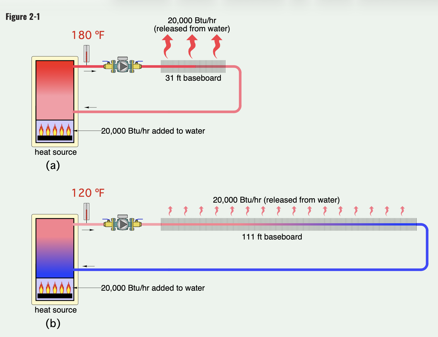
Idronics 23 talks about Thermal Equilibrium
 Bob "hot rod" Rohr
trainer for Caleffi NA
Living the hydronic dream0 -
@hot_rod : "Boilers have safety devices, high limits, to prevent over temperature conditions, If the emitters can overpower the boiler, a low temperature protection should be added."
And I feel like we're circling in on the answer to why a boiler might malfunction when it's over-pumped.
It's not that the water is moving "too fast," per se. It's that the higher the flow, the higher the output of the radiators, and by increasing the flow the system becomes over-radiated — the radiators have more capacity than the boiler.
In an over-radiated system you're going to see wild swings in water temperature. When all the radiators are calling, the water temperature is going to drop to a temperature where the system is in balance. But when they're not all calling it's going to be able to hit its design temperature. These wild swings aren't good for the boiler, and they're not good for comfort.
Reducing the flow to where the radiators match the boiler will solve this problem.
0 -
An "over-radiated system will basically drive down the boilers operating temperature. This is a fin tube example, a high mass CI rad system would have much more thermal lag, making quick adjustments tricky.
We have seen this numerous times over the years with large volume large radiator conversion systems. Those owners come here looking for a way to return protect their boilers. As the see the boiler never getting out of condensing mode.
I feel the answer is in proper balancing. A balance valve is the fine tuning device, used for getting even heat distribution and best system efficiency. It could be as simple as the wheeled valve seen on CI radiators.
Obviously there is no reason to grossly over-pump, if the tech can acquire enough info to right size the pump, do that. That is not so easy on a gravity system designed and maybe modified over 50 yrears.
The final adjustment for mismatches you describe would be balance, not reduce speed to the lowest common speed for the smallest load. All the rooms could, should get just the right amount of flow/ heat output.
Everyone has a different idea of what that right amount may be especially in one thermostat multi unit cases. A property owner has the responsibility to provide a minimum amount of heat to maintain a code approved temperature. But unless there is user adjustability, I think there will be unhappy occupants. Which is another common thread here.
What is still missing in my mind is how to right size a circ on a gravity system and the reason for the decision.
Bob "hot rod" Rohr
trainer for Caleffi NA
Living the hydronic dream0


Categories
- All Categories
- 87.7K THE MAIN WALL
- 3.3K A-C, Heat Pumps & Refrigeration
- 59 Biomass
- 430 Carbon Monoxide Awareness
- 129 Chimneys & Flues
- 2.2K Domestic Hot Water
- 5.9K Gas Heating
- 122 Geothermal
- 170 Indoor-Air Quality
- 3.8K Oil Heating
- 79 Pipe Deterioration
- 1.1K Plumbing
- 6.6K Radiant Heating
- 396 Solar
- 16K Strictly Steam
- 3.5K Thermostats and Controls
- 56 Water Quality
- 51 Industry Classes
- 51 Job Opportunities
- 17 Recall Announcements