Hydronic heating system

I’m designing a heating system for a class project .
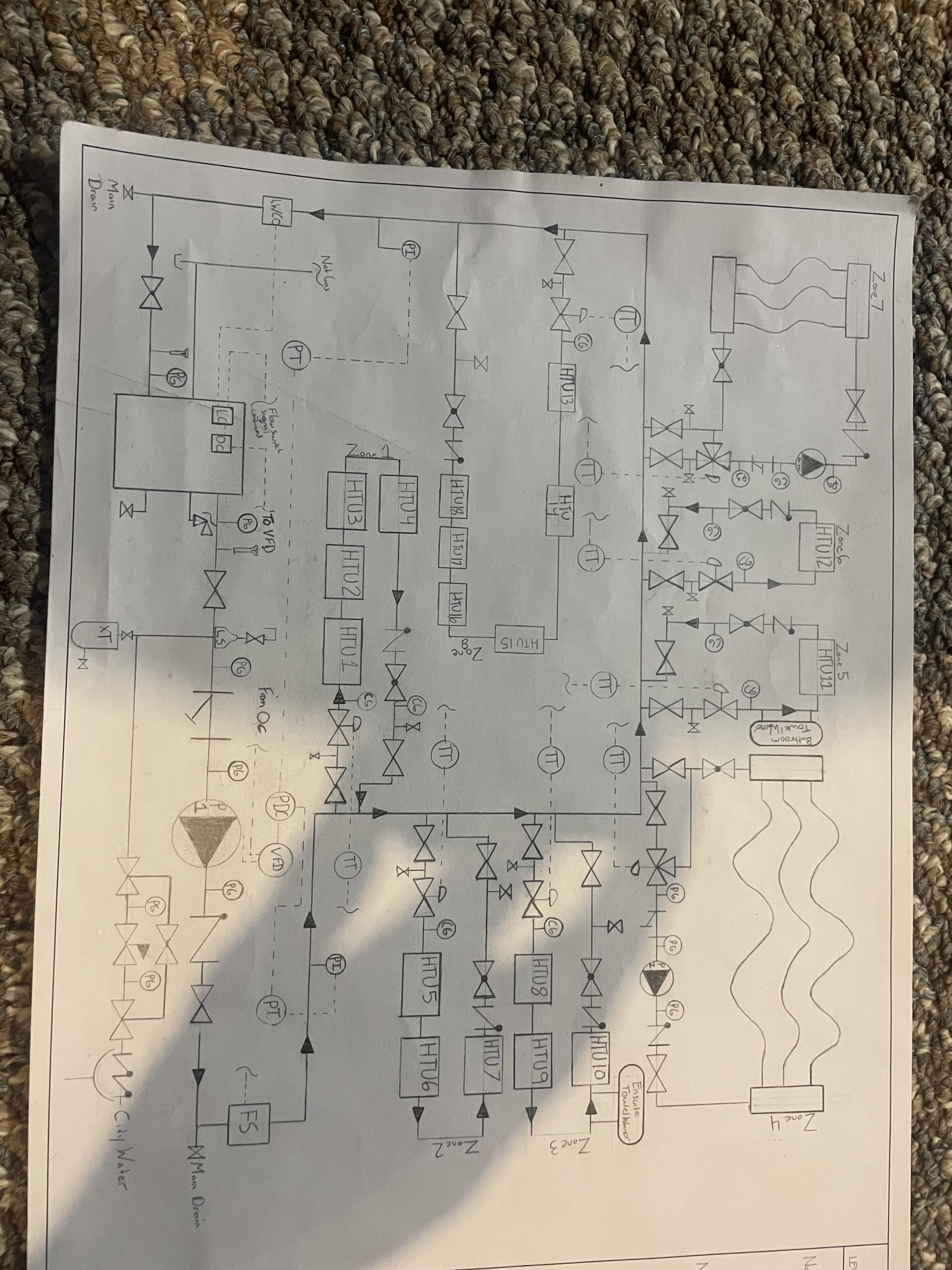
My heating system for my project is a one pipe system. My main is one pipe I have closely space tease for each zone and each zone is installed with an isolation zone valve, control valve, check valve and globe valve and independent drains.The htu in each zone are piped in series. I’m doing the math and accounting for the temperature drop In each zone and adjusting the emitter size for the zone that follows . Does this set up work ? I’ve. Correctly sized the primary circulator so each zone doesn’t need a circulator ? I have independent circulators for my radiant in floor heating
Comments
-
looks like a series primary loop
So every takeoff with a set of close tees needs a circulator sized for that circuit
Yes you loose temperature at each take off that is operating
With temperature and gpm numbers for each set of tees you can calculate that
Bob "hot rod" Rohr
trainer for Caleffi NA
Living the hydronic dream2 -
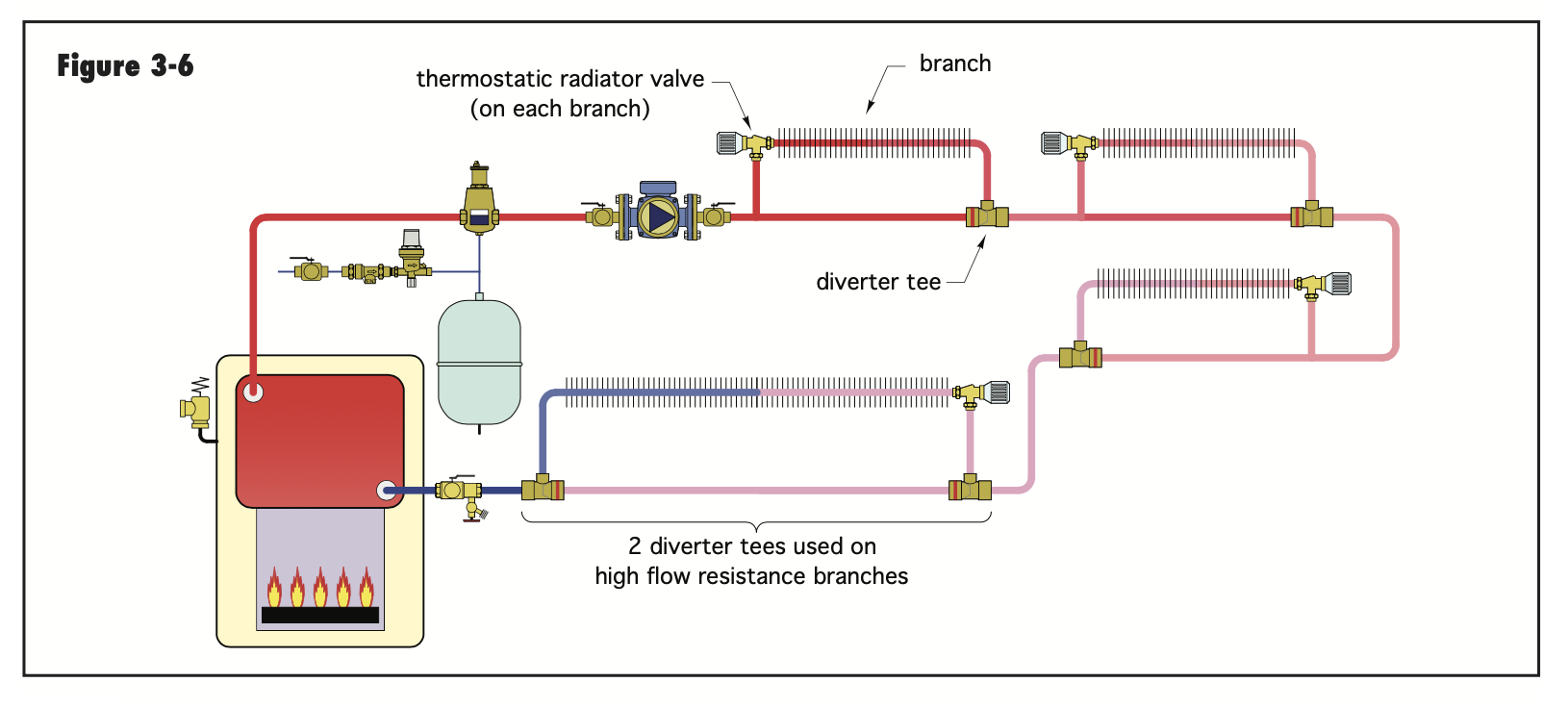
or use monoflo tees but you definitely would need to write and solve the system of equations to make monoflo work here.
0 -
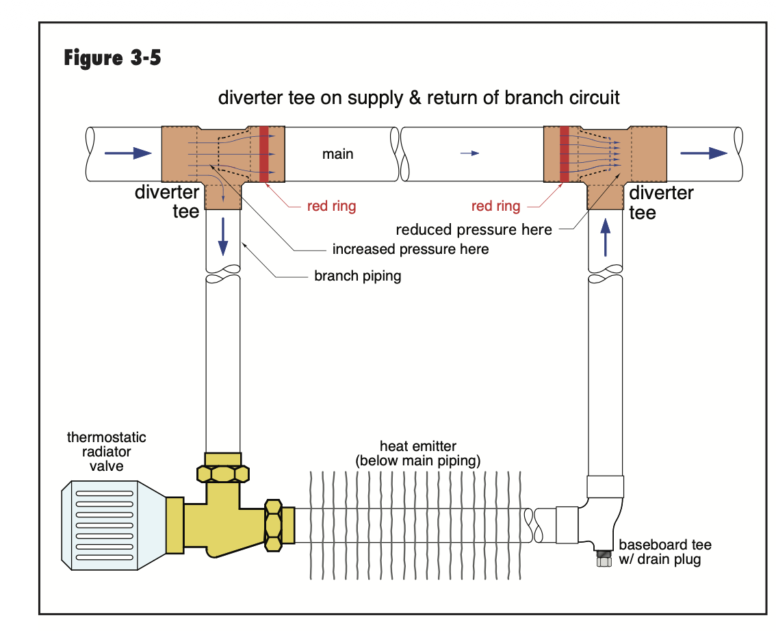
Here mare some examples of a diverter "one pipe system. It takes a specific tee fitting. The math to calculate the system you show would be complex. You have temperature and pressure drop tom account for. It is still a series circuit, so the last take offs would be cooler SWT.
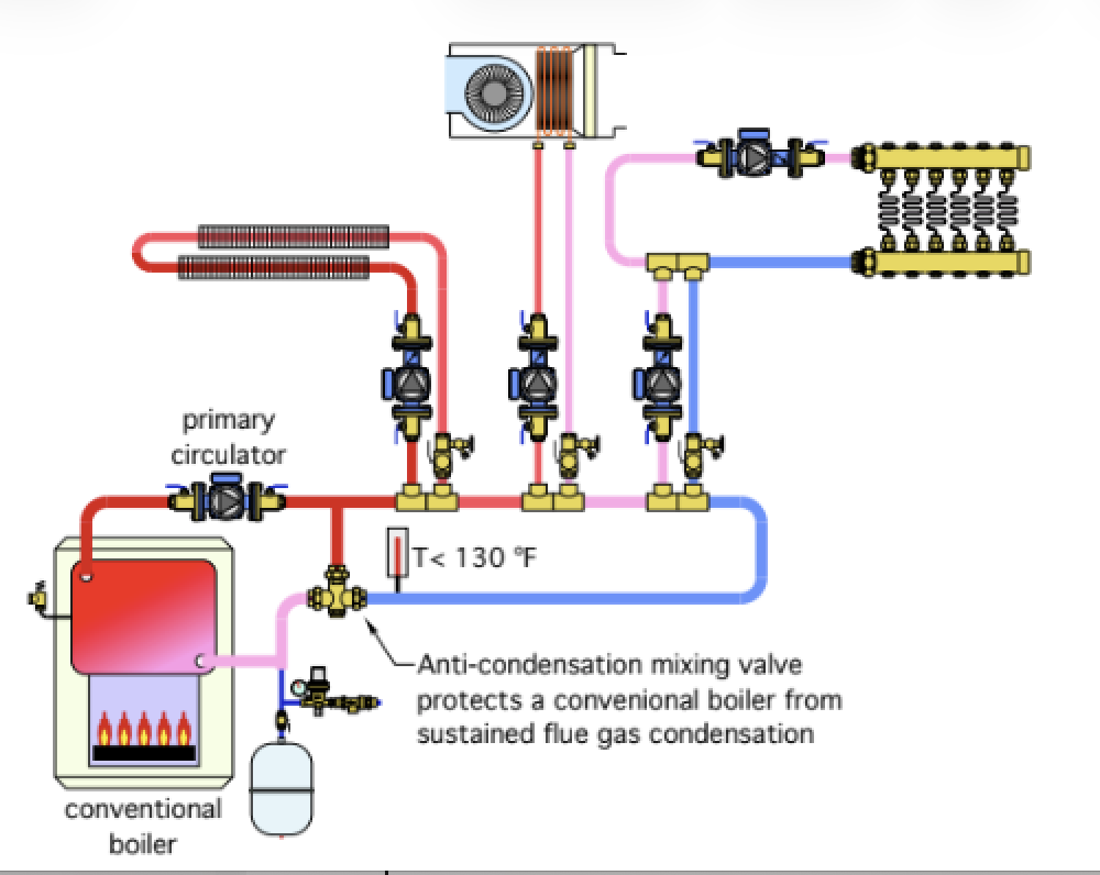
Various primary secondary methods. This shows the boiler as a secondary.
The boiler, if a low pressure drop, could be in the loop also.
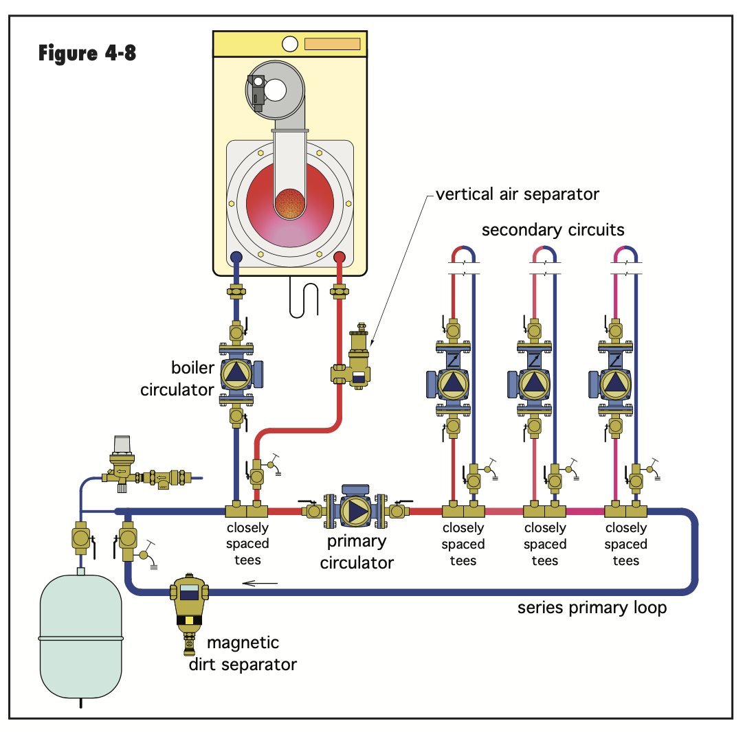
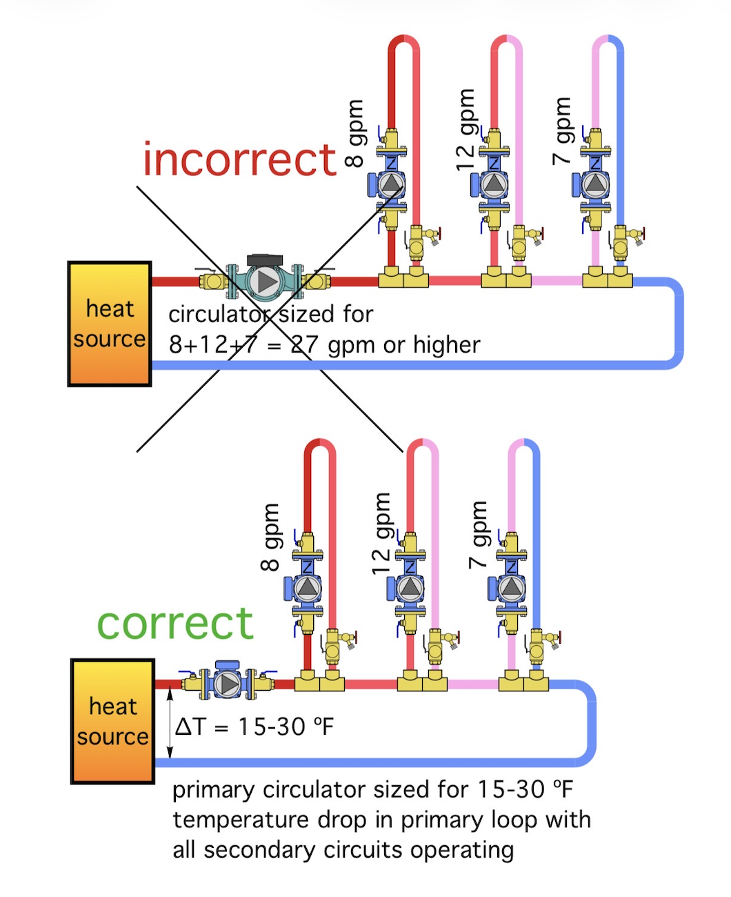
There is a misconception that then primary circulator needs to be at least as great as all the secondary flow rates.
Actually that primary circulator is sized by the overall temperature drop when all secondaries are running. Generally 15- 30 ∆ around the loop.
A larger delta design when the secondaries have a wider range of temperatures, as yours do.
A tighter delta when secondaries are similar in temperature
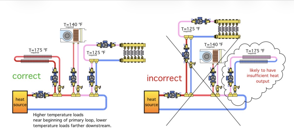
Higher temperature circuits first.
 Bob "hot rod" Rohr
trainer for Caleffi NA
Living the hydronic dream0 -
ok thanks guys . Does the system make sense ?
0 -
I don't want to knock what your trying to do. Yes, I think it will work but as mentioned above you need zone circulators to create a Pd so the water will flow.
There may be simpler was to do this but it looks like it will work
0 -
if you wanted to be completely insane about it you could do it with different size pipe in the main between the tees vs the rest of the main and sizing the branches to get the right flow in the branches. I would not recommend building that as a production system but it could be an interesting academic exercise.
like when i tried to design a simulated processor without a clock and gates but with signals that all propagated at equal speeds through the different sections. probably would have got a better grade if I explained that better.
0 -
The two radiant zones will work fine, pump from the mixed port
I doubt any other circuit will see any flow without pumps
Even when pumped 13-18 will see a low supply temperature as the cool radiant return is dumping in upstream
Bob "hot rod" Rohr
trainer for Caleffi NA
Living the hydronic dream0 -
If it were me,
I want a simple to use and understand system and in order to receive an A+ I would do one thing and one thing only.
Please start over and
begin again with an overhead gravity system and eliminate all the scribbling work you have already done and use the power of 170-180 degree Fahrenheit hot water rising and falling with no electricity needed to heat the entire place. It has been done and there are gravity hot water systems that are still in use today heating homes and buildings.🙂
 1
1


Categories
- All Categories
- 87.7K THE MAIN WALL
- 3.3K A-C, Heat Pumps & Refrigeration
- 59 Biomass
- 430 Carbon Monoxide Awareness
- 127 Chimneys & Flues
- 2.2K Domestic Hot Water
- 5.9K Gas Heating
- 121 Geothermal
- 170 Indoor-Air Quality
- 3.8K Oil Heating
- 79 Pipe Deterioration
- 1.1K Plumbing
- 6.6K Radiant Heating
- 396 Solar
- 16K Strictly Steam
- 3.5K Thermostats and Controls
- 56 Water Quality
- 51 Industry Classes
- 51 Job Opportunities
- 17 Recall Announcements