Pulling a 'C' wire from a Honeywell R132A2K-2 relay box

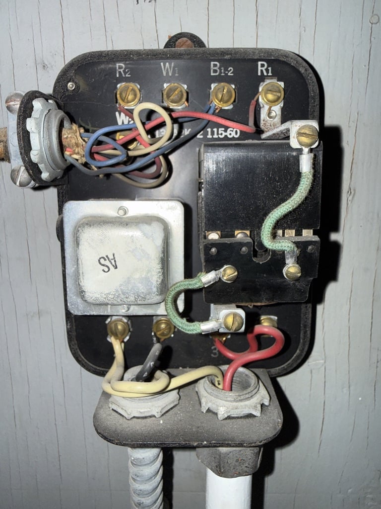
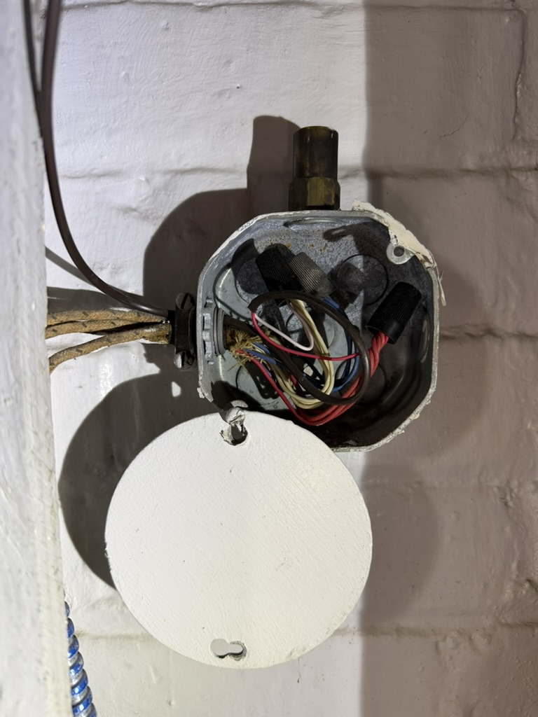
I have a multiple-zone oil-fired furnace using the Honeywell R132A zone relays. Some of these relays are controlled by old Honeywell T87F thermostats, while one is controlled by a bit more modern RobertShaw/Maple Chase 9600 digital thermostat. With both the T87's and the 9600 thermostats, the blue and red thermostat wires are connected together at each thermostat. I wish to replace all these thermostats with 'smart' thermostats which require a 'C' wire. Attached is a photo of the R132A with its cover removed. I also have access to the back-side of these units where the secondary terminals of the 24VAC transformer can be found. My thought is to separate the blue and red wires at each thermostat, and use the blue wires as my C-wire, removing it from B1-2 at the R132A and soldering it to the appropriate pin on the 24V transformer. But I am not quite confident as to the function of the B1-2 wire, and wonder if this procedure will cause me trouble.

Comments
-
I’m sure there’s a way to find a “C” wire in there somewhere, but it may not be an easy connection.
If you don’t mind spending some money for an easier way to wire the thermostat, get a Taco SR501 that gives you a “C” terminal. Taco or Caleffi also have them for multiple thermostats.
You will need to make sure that the on board transformer is large enough to power the thermostat(s) whichever one you choose.
My guess that the B1-2 and R2 terminals don’t go to your thermostat, rather they are dry contacts that turn on the boiler.8.33 lbs./gal. x 60 min./hr. x 20°ΔT = 10,000 BTU's/hour
Two btu per sq ft for degree difference for a slab0 -
It looks like there is no 'C' terminal as it is thought of now. However the non-switched (by the thermostat) side of the transformer is usually the 'C' wire functionality. However keep in mind that the relay was probably never designed to have additional loads connected do it. Adding additional loads may make the transformer fail due to mild overloading.
 National - U.S. Gas Boiler 45+ Years Old
Steam 300 SQ. FT. - EDR 347
One Pipe System0 -
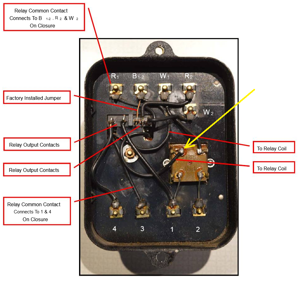
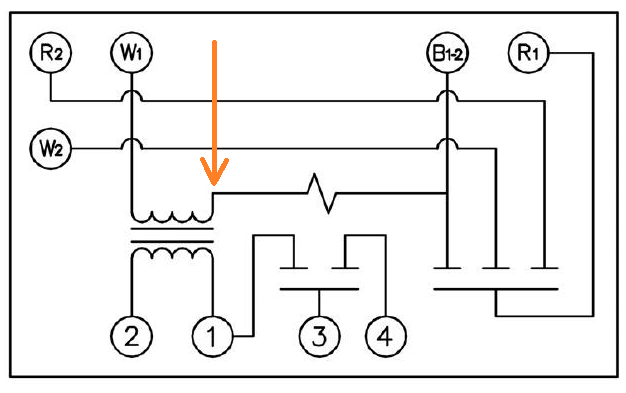
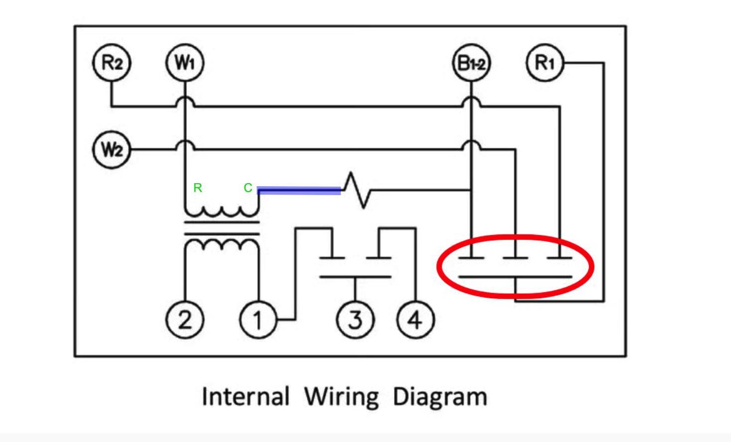
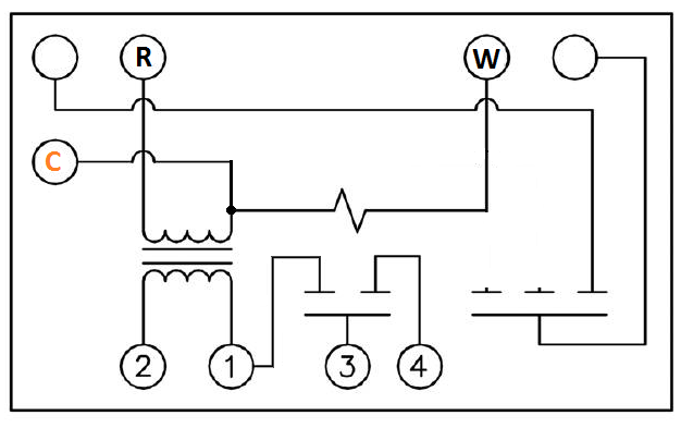
There is no terminal that equals R and C from the transformer. W1 is the only terminal directly connected to the transformer. If we call that R for thermostat purposes then the C is connected internally to the relay coil and there is no screw terminal does that particular node of the control (the Blue highlighted wire). The W for the thermostat purpose would be B1-2
This is an obsolete control technology from more than half a century ago known as Series 10, developed by Honeywell.
A Series 10 thermostat uses a three-wire configuration: R, W, and B.
In a Series 10 system:
- When R and W close, the thermostat does not directly energize the burner or main control relay.
- This initial contact establishes part of the control circuit but does not yet complete the relay coil circuit.
- When B and W close (while R and W remain closed), the relay coil circuit is completed and the relay pulls in.
This staged switching arrangement was intentionally designed to create a wider operating differential through the sequencing of contacts.
Once the heating appliance begins delivering heat to the space, the room temperature can rise quickly. If the relay were allowed to drop out immediately upon slight temperature rise, short cycling could occur. To prevent this, the R–W connection remains closed, which holds the relay energized until the thermostat fully satisfies and opens the R–W connection at the end of the heat call.
This “make-before-break” contact sequencing is characteristic of Series 10 controls and differs significantly from modern 24-volt control systems.
I have a link to a Honeywell booklet that explains Series 10 controls in detail.
But this will not help you with connecting a smart thermostat to this R132A control. There is no screw terminal anywhere on the control that will get you where you need to be. Your best bet is to replace that R132A with a Taco SR501 that has a dedicated C terminal for smart thermostats
Edward Young Retired
After you make that expensive repair and you still have the same problem, What will you check next?
 1
1 -
It could be modified (however there is still the transformer loading issue), screw terminal functions could be reassigned, but the Taco SR501 is probably the most practical solution.
 National - U.S. Gas Boiler 45+ Years Old
Steam 300 SQ. FT. - EDR 347
One Pipe System1 -
That might work if the system does not have another series 10 device after that R132A that requires the use of the rest of the terminals. And even of you don't have other controls after that R132A, Do you really want to take the control apart and start redesigning the internal wiring with a soldering iron?
I know that there are some that would do it, (including me) but you take that system into your own hands after a modification like that. If it happens to be discovered after an event that requires an insurance inspection you might be left holding the bag with cancelled coverage. (that is not something that happens very often if you are interested in saving $$$ by using the existing control.) Just a heads up!
Edward Young Retired
After you make that expensive repair and you still have the same problem, What will you check next?
0 -
@EdTheHeaterMan Just presenting options, in general (for the average public) I think the Taco SR501 (or like) is probably the best option.
National - U.S. Gas Boiler 45+ Years Old
Steam 300 SQ. FT. - EDR 347
One Pipe System 1
1 -
Agree @109A_5
As I stated I might even try your idea given the opportunity. But not for a customer.
Edward Young Retired
After you make that expensive repair and you still have the same problem, What will you check next?
0 -
Thanks, everyone. This is all great info. For multiple reasons (less money, less labor, etc), I would prefer to use the existing Series 10 equipment, rather than upgrading to a Taco unit. It's sort of an historic home, and I am fascinated by this old equipment. So here is what I am now thinking: Since it appears that my thermostat wiring is only 3-wire, and all conductors seem to be used in the current configuration, I need to free up a conductor for use as the C wire, and attach (solder) that conductor to the appropriate point at the 24VAC transformer.
The current configuration has the R1 screw terminal attached to the red conductor, and the B1-2 screw terminal attached to the blue conductor. And the W1 screw terminal is attached to the white conductor. At the 9600 thermostat, the white conductor lands on the Rh terminal (which is also bridged ro Rc), and BOTH the red and blue conductors land on the W terminal.
So since both red and blue conductors are tied together at the thermostat terminal, I figure that I could free up this blue wire (to use as a C wire) by disconnecting it from the red wire at the thermostat, unscrewing it from the B1-2 screw terminal in the Honeywell relay box, and then bridging the R1 to the B1-2 in the Honeywell box. After this step, I am pretty sure that electrically, nothing has really changed, and now I have a free (blue) wire that I can tie to the relay's 24VAC transformer and therefore use this blue wire as a C wire for the smart thermostat that I will install (replacing the 9600). Does this all make sense? Of course the extra loading on the 24VAC transformer might still be an issue, but I am willing to take that risk. (If it burns out, I can always go the Taco route! 😀)
1 -
It would be nice to get the whole picture. You have two wire bundles coming into the transformer relay. One to the thermostat and the other to your boiler. The one to the boiler might be daisy chained with other R132A's. Where do they land at the boiler?
8.33 lbs./gal. x 60 min./hr. x 20°ΔT = 10,000 BTU's/hour
Two btu per sq ft for degree difference for a slab0 -
What's the va rating on the transformer in the "historical" switching relay?
0 -
Correct, I have not been focusing on that. I have found a junction box where all of the R2/W2/B1-2 connections from the various R132A's are tied together (each conductor color is assigned its own wire nut),
and then another thermostat wire that goes from this junction box to a splice (again with wire nuts) to another thermostat wire that goes to the burner unit.
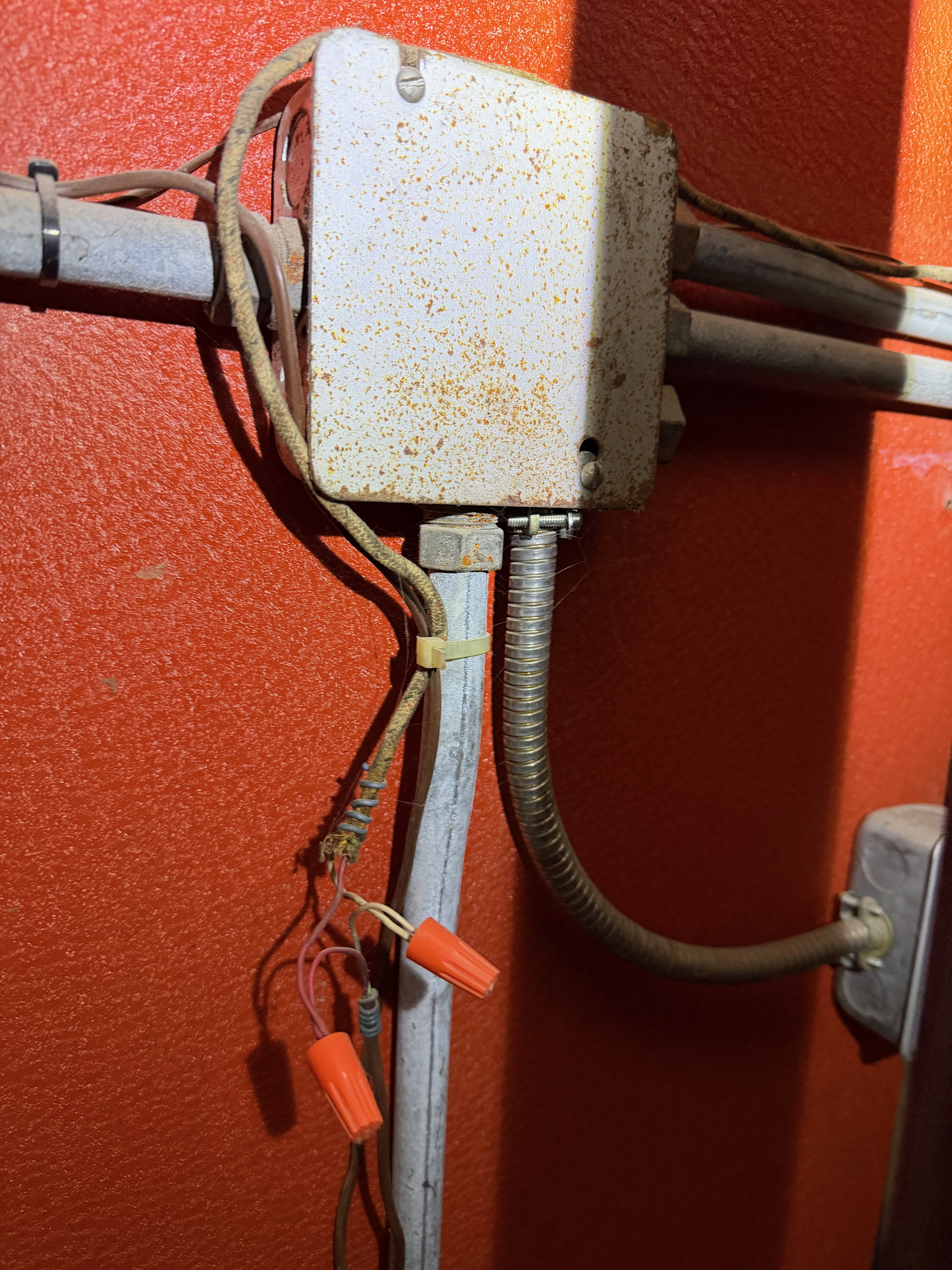
One thing I now notice is that these blue wires ultimately don't land anywhere unique, either, suggesting that I could probably just disconnect these wires from the B1-2 screw terminals in each of the R132A's.
0 -
" I have a multiple-zone oil-fired furnace using the Honeywell R132A zone relays. Some of these relays are controlled by old Honeywell T87F thermostats, while one is controlled by a bit more modern RobertShaw/Maple Chase 9600 digital thermostat. "
As @Alan (California Radiant) Forbes stated the bigger picture would help.
Where does the B2, R2, W2 wires go to ? It does not seem like that would go to another thermostat.
It seems you have no series 10 thermostats. You mention multiple R132A zone relays. Is there any other zoning equipment, circulators or zone valves ?
Freeing up the blue wire seems to be the least of the concerns I would have.
National - U.S. Gas Boiler 45+ Years Old
Steam 300 SQ. FT. - EDR 347
One Pipe System0 -
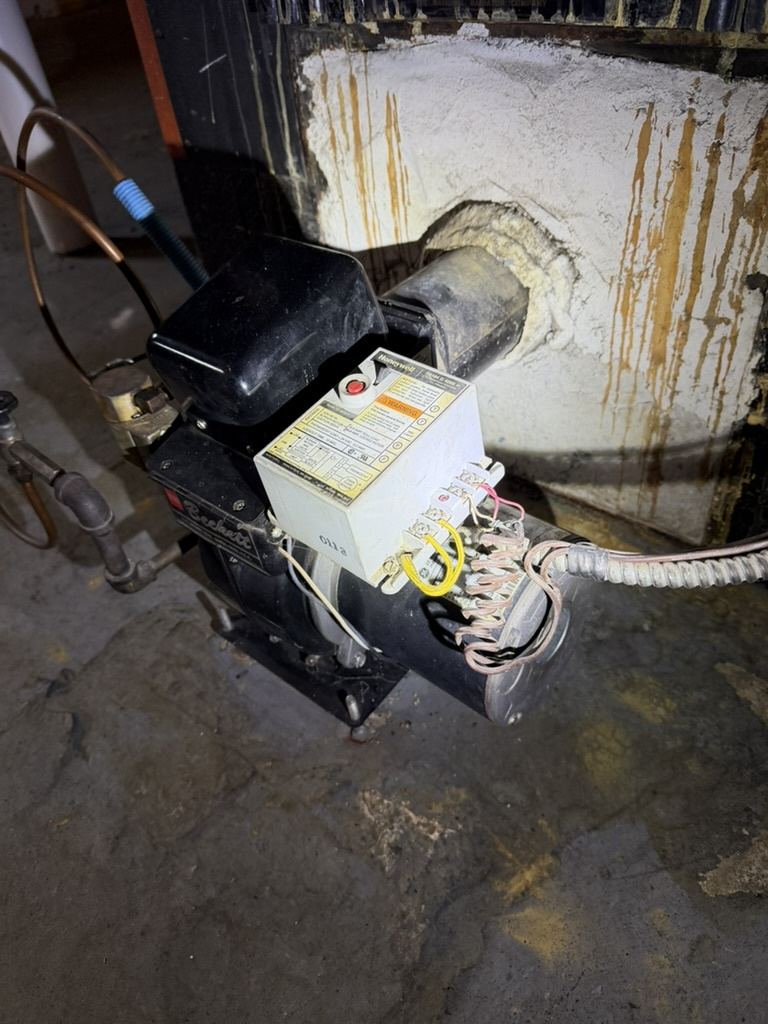
All of your controls on the boiler have been upgraded to series 80 controls as far as I can see. The old Series 10 stack relay RA117A primary control has been replaced with a Series 80 Protectorelay R8184G. You are using a 2 wire thermostat. What value is there in keeping the last of the Series 10 controls? The rounded black cover?
If look on e-bay you may be able to find something that you can stuff under that black cover
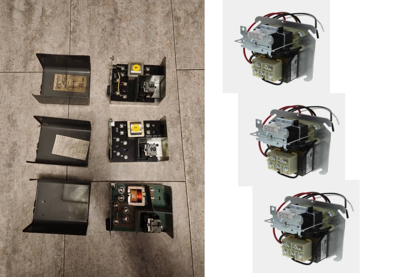
Above are from 2 different e-bay listings.
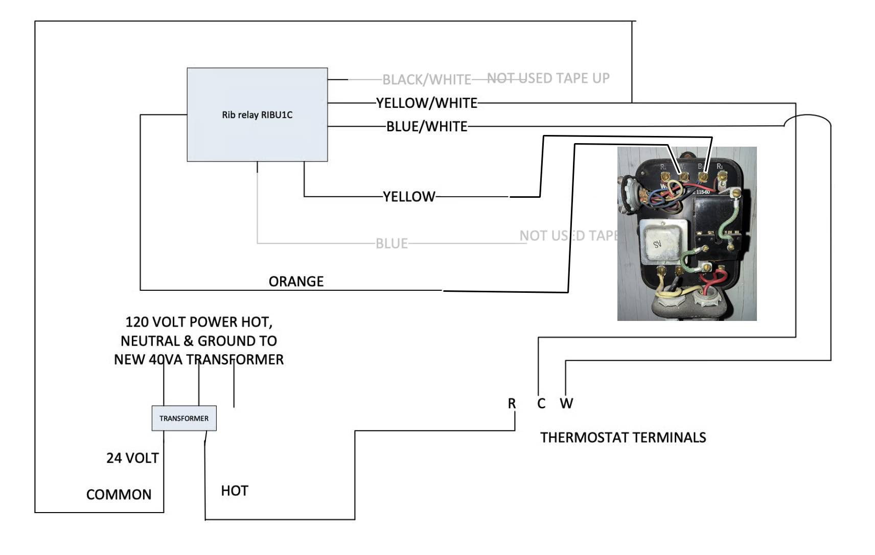
Or a better idea is to use an isolation relay with a separate transformer that has enough power to operate both the thermostat and the relay.
Either way, you will need to buy something more that what you already have. Here is one isolation relay with transformer that was posted by someone else that I liked. I have modified it with your relay connected
Edward Young Retired
After you make that expensive repair and you still have the same problem, What will you check next?
0 -
The B1-2/R2/W2 from the different R132As all get tied together and ultimately go to signal the burner to fire up. The red and white (line voltage) wires (entering the bottom conduit on the right hand side of the picture that I included in my original post) go to a circulator.
0 -
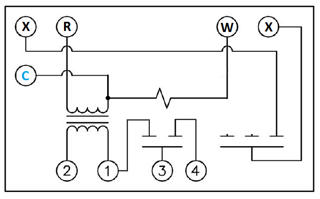
I guess if you want to go forward with your experiment I would modify the R132A this way, where the X - X are paralleled across the multiple R132A relay's to control the burner. Relabel the connections and document the changes so you or someone else can figure it out in the future without spending a lifetime there or just ripping it all out in frustration. And only one thermostat per R132A.
At least where I live, I probably would not do this change this time of year in case things go badly.
 National - U.S. Gas Boiler 45+ Years Old
Steam 300 SQ. FT. - EDR 347
One Pipe System0 -
just a quick note to say that I modified the R132A (disconnecting the R1 terminal from the common contact on the relay, and then directly connecting it to the other leg of the 24VAC transformer, then using the red wire connected to the R1 screw terminal as my C-wire to the smart (Nest) thermostat). And it all works. Thanks, all, for weighing in with your comments/suggestions. (Studying the old Honeywell Handbook on Series 10 controls was key to my gaining the confidence in this approach.)
1 -
This is interesting information. You may encounter a problem in the future with the OEM transformer in that R132A relay because it may not be as powerful as you think. In looking at Honeywell archived manuals for that control there is no mention of the VA rating of that transformer. Some other relays like the Honeywell RA889A switching relay that uses similar switching functions and relays used 24 volt 12 VA transformers to power that same small relay coil that is used in the R132A.
Since there is no documentation on that R132A transformer, the only sure way to determine what power rating that transformer has is to look and see if it is printed on the transformer itself.
If at some point, you find that the transformer fails with the extra load of the thermostat’s power draw, you can either replace the transformer inside the existing control or replace the control with one of the recommended options above. You have options now that you have already modified the R132A.
Edward Young Retired
After you make that expensive repair and you still have the same problem, What will you check next?
0

Categories
- All Categories
- 87.5K THE MAIN WALL
- 3.3K A-C, Heat Pumps & Refrigeration
- 59 Biomass
- 429 Carbon Monoxide Awareness
- 124 Chimneys & Flues
- 2.2K Domestic Hot Water
- 5.9K Gas Heating
- 119 Geothermal
- 168 Indoor-Air Quality
- 3.8K Oil Heating
- 78 Pipe Deterioration
- 1K Plumbing
- 6.6K Radiant Heating
- 394 Solar
- 15.9K Strictly Steam
- 3.5K Thermostats and Controls
- 56 Water Quality
- 50 Industry Classes
- 50 Job Opportunities
- 18 Recall Announcements