Questions about Replacing old OJ Microline Thermostat with UWG4-4999

Hi,
We purchased an older home a couple of years ago, and the previous owner had added an extension that included a 2-car garage in the back and above the garage an enclosed sun room and they had radiant floor heating installed in the sun room area.
The flooring in that sun room area is tile, and there were 2 of the older OJ Microline thermostats (OJ ELECTRONICS MTC-2991-UCH), so I think that there are 2 heating grids under the sun room floor.
A couple of weeks ago, one of the old thermostats stopped working, so I ordered two of the OJ Microline UWG4-4999 thermostats, and we replaced the non-working MTC-2991-UCH with one of the new UWG4-4999, but I am a bit confused about the wiring (I didn't do the replacement but I was watching):
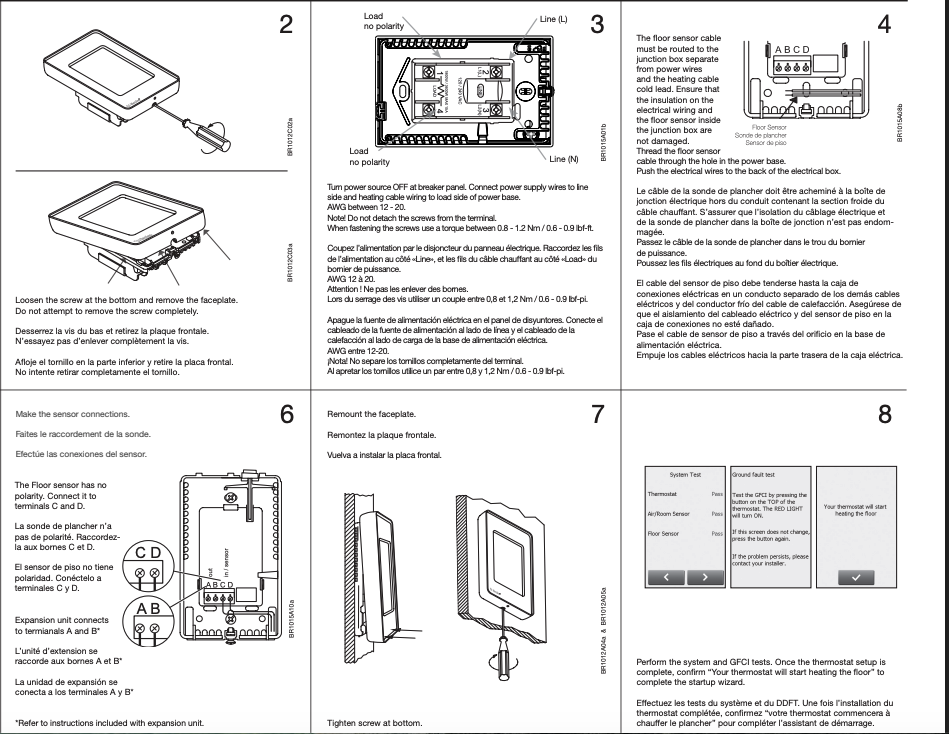
There were 2 sets of red-green wire (each red+green wire pair was in a separate sleeve) in the wall box and it looked like the UWG4-4999 has a kind of a terminal strip with 4 attachment/contact points, labeled from left-to-right when looking at the back side:
out in
=======
A B C D
I don't know why, but I think that the person that did the replacement thermostat installation yesterday connected the 2 green wires to the A and the B contacts, and the connected the 2 red wires to the C and D contacts, which am thinking was not correct?
After he had completed the wiring and we turned the breaker on and when through the startup prompts, there were 3 tests: The first 2 test steps passed, and the 3rd test step, the floor sensor test, failed.
So I was looking at the "wire diagram" docs that OJ Microline has on their website, and I am a little confused (maybe a lot) about a couple of things:
- I am guessing that each of the sleeved red+green wire pairs goes to on floor sensor, and that maybe the reason that there were 2 pairs was because the sensors get buried in the floor, so the 2nd red+green pair is a backup in case the first pair fail later on, but if that is the case, should the wires from both red+green pairs actually be connected to the contact points on that terminal strip? Or should just ONE of the red+green pairs be connected and only to the C and D contacts?
FYI, I have the thermostat set for "room sensor only" at this time. I think I had tried setting it to floor or room+floor protection, but when I did that the thermostat displayed showed 39F for the current temperature.
I think that I'd like to set it to room+floor protection, but I think that I can't while it is wired the way it is wired now?
Also I was looking at a bunch of stuff after the install, because I am not at all sure if the that thermostat is actually even heating that part of the floor, and I THINK that it is heating:
- The new thermostat "Energy Usage" is showing that it is using power
- I put a physical thermometer on that section of the floor and overnight it looks like that is showing 90F now.
I'd really like to get the thermostat wiring correct so that we can use the floor sensor, but besides just getting the wiring correct, I have questions like where should the 2nd red+green pair be connected to… or maybe they should just be left unconnected?
Sorry for the longish post!!
Thanks,
Jim
Comments
-
Is this a line voltage thermostat for electric radiant?
Do you have the manual that came with it? It shows where the wires connect, but you need to determine which two wires are the floor sensor. An ohm meter could help with that. The sensor wires may be a smaller stranded wire type. The liune voltage may be a solid wire?
This is an example of a wiring guide, I'm not sure it is for the model you have?
Attach some pics.
 Bob "hot rod" Rohr
trainer for Caleffi NA
Living the hydronic dream0

Categories
- All Categories
- 87.7K THE MAIN WALL
- 3.3K A-C, Heat Pumps & Refrigeration
- 59 Biomass
- 430 Carbon Monoxide Awareness
- 129 Chimneys & Flues
- 2.2K Domestic Hot Water
- 5.9K Gas Heating
- 122 Geothermal
- 170 Indoor-Air Quality
- 3.8K Oil Heating
- 79 Pipe Deterioration
- 1.1K Plumbing
- 6.6K Radiant Heating
- 396 Solar
- 16K Strictly Steam
- 3.5K Thermostats and Controls
- 56 Water Quality
- 51 Industry Classes
- 51 Job Opportunities
- 17 Recall Announcements