CG400 LWC Does Not Cut Off Autofeeder

Hello, I’m trying to set up a new boiler with a CG400 low water cut off. I have 24v wires connected to a relay that runs a Hoffman feed tank. When the signal for low water goes on, the relay runs the pump. However, the CG400 does not shut the pump off.
Am I missing something obvious? There is nothing in the instructions saying how to hook this up with a feed tank. I have the relay wired to the A and C terminals on the CG400.
Comments
-
You need 4 wires to do this. You have a 24 volt low water cut off correct?
you need constant 24 volt power to terminals #1 & #2 on the LWCO. terminal 31 is 24 volt hot #2 is the common.
Ftom the LWCO to your 24 volt relay you need a common (term 32) and a hot from "A" the alarm terminal to power the feeder.
At least thats the way it looks to me.

 2
2 -
it would really be a lot easier to understand if the manual showed the internal relay connection to the terminals on the safgard
0 -
Is there 24 Volts between terminal '2' and 'A' when you expect the relay to drop out and shut off the pump ?
 National - U.S. Gas Boiler 45+ Years Old
Steam 300 SQ. FT. - EDR 347
One Pipe System0 -
@109A_5.
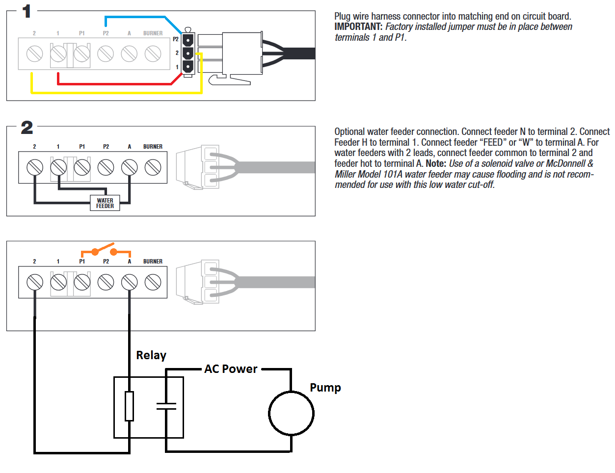
AFAIK 2 is common and A is the alarm terminal which is powered when you go off on LW. Probably not the best way to control a pump but the 4 terminals are 1-hot and 2 common constant power . A get powered when low on water and P2 gets powered to run the burner.
P1 & P2 are dry contacts. P1 gets powered by jumping it to 1. But if switching the burner limits through P1 & P2 you take the jumper out.
0 -
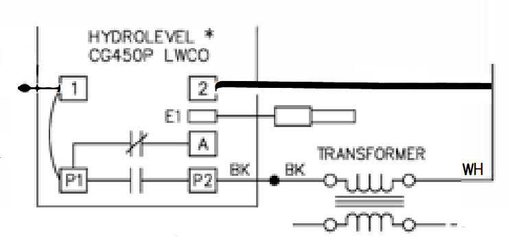
@EBEBRATT-Ed I think we agree on the functions of the LWCO's terminals. Here (below) is another terminal point of view from a Peerless manual, since Hydrolevel seems to not use normal relay nomenclature.
I think Hydrolevel's nomenclature is consistent across their product line. My diagram above is how I envisioned the OP wired his system, not necessarily my suggestion. The Orange switch illustrated above is one half of the LWCO's internal relay.
The OP claims the pump latches on; "However, the CG400 does not shut the pump off."
So I asked the question;
"Is there 24 Volts between terminal '2' and 'A' when you expect the relay to drop out and shut off the pump ?"
Thinking if when the OP's CG400 LWCO is satisfied there should no longer be 24 VAC between terminal '2' and 'A' to energize the added relay controlling the pump. Since the terminal '1' is jumpered to 'P1' and the internal contact to 'A' (Alarm ?) opens since the water level has been satisfied.
There needs to be a divide and conquer point to determine a troubleshooting direction. I chose is there 24 VAC between terminal '2' and 'A' after the CG400 LWCO is satisfied and no longer in alarm.
If that is true and the added relay drops out and the pump continues to run it is not the LWCO or wiring the OP used. It may be some kind of electrical latch within the Hoffman feed tank system that keeps the pump running and not the CG400 LWCO or the added relay. In essence the CG400 LWCO and the added relay may just be a trigger and some other limiting device needs to be satisfied (EDIT: or ultimately disabled) to shut off the pump.
BTW it appears Hydrolevel keeps its internal relay energized when in the normal operating mode, a fail-safe.
So when not in alarm 'P1' to 'A' contact should be open and 'P1' to 'P2' is closed to power the burner.
 National - U.S. Gas Boiler 45+ Years Old
Steam 300 SQ. FT. - EDR 347
One Pipe System0 -
Throughout all above I assume the CG400 LWCO has constant 24 VAC power to terminals 1 and 2, whether in alarm or not, pump running or not.
National - U.S. Gas Boiler 45+ Years Old
Steam 300 SQ. FT. - EDR 347
One Pipe System0 -
@109A_5
The picture you provided shows the circuit the best in the third diagram down. The Hoffman feed tank runs off a basic on/off relay that as far as I know was not provided by the manufacturer.
Through some further testing, the alarm circuit on the LWCO stays on for about a minute after it is triggered and the water level restored. This duration would work if the Hoffman pump was slower, but it overfills the boiler. I may be able to add a timer that interrupts the alarm signal after 10ish seconds or whatever the proper time would be.
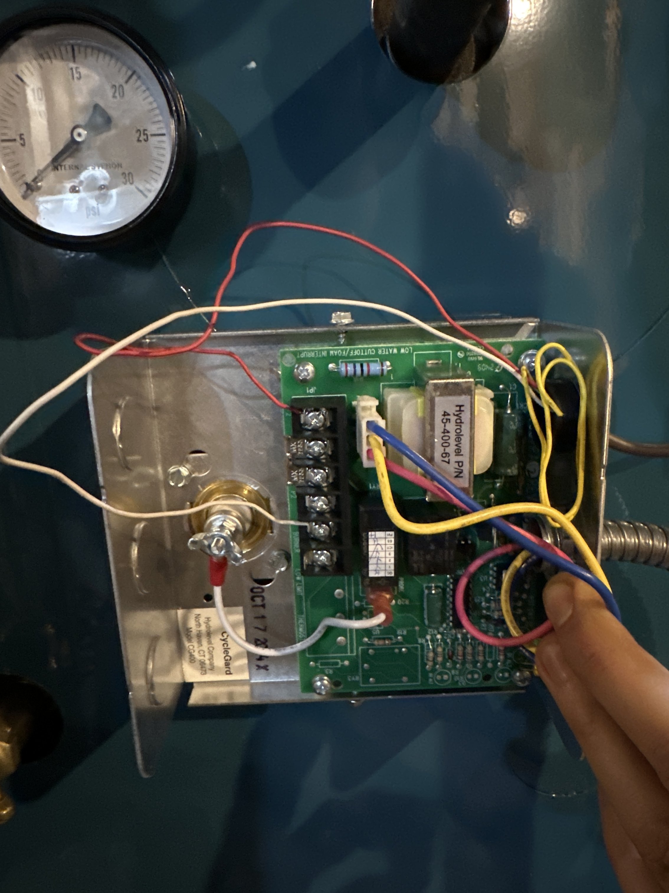
I have since removed the CG400 and installed the M&M 67 float style LWCO that was on the old boiler. However, the way I currently have that wired, the burner stays energized when the pump relay is running. This could be dangerous if the feed tank were to run dry. The LWCO would not be able to shut off the burner.The red lines show where I have the relay wired right now. Somehow this set up also feeds power to the burner. Where should I land the wire on the left?
0 -
I wondered about a delay with the CG400 but did not see it mentioned in the manual. The M&M 67 is quite capable of burner control and water feeder control when wired up correctly. You could use both the M&M 67 and the CG400 to protect the boiler.
 National - U.S. Gas Boiler 45+ Years Old
Steam 300 SQ. FT. - EDR 347
One Pipe System0 -
Neither of those controls is really correct to run a feed pump with. Not saying it can't be done.
The reason is there is very little differential between the Low water cut off switch and the feeder/pump switch.
You really need a low water cutoff and a pump control to do this right. In many cases with one control the burner will cut off before sufficient water is in the boiler.
The other reason is your operating the feed pump at the "low water level" maintaining the boiler "minimum water level".
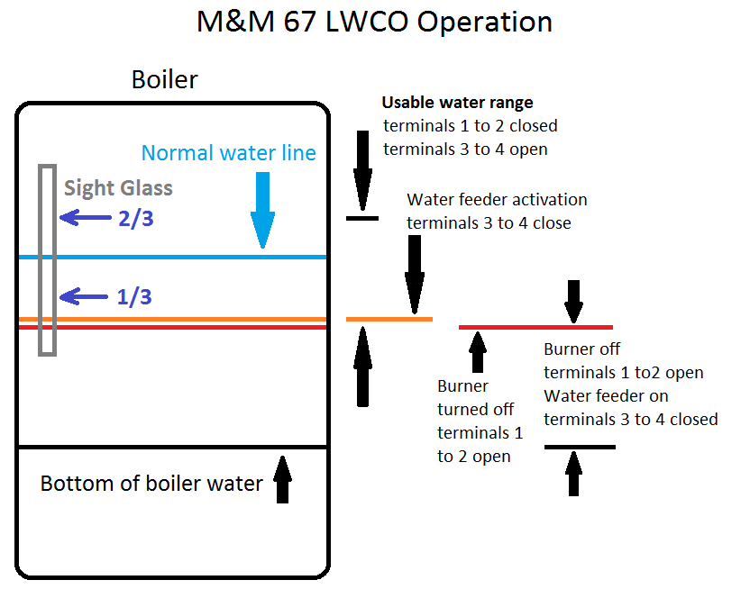
To do it right the pump control should be maintaining the water level at 1/2 a glass and the low water cut off at the minimum safe water level.
0 -
That's why I mentioned "You could use both the M&M 67 and the CG400 to protect the boiler."
To expand on that more the CG400 could be at the minimum water level with a limited fill timer, the M&M 67 could be piped at the 1/2 way point sweet zone. Both or just the CG400 would shut down the burner depending on what you want.
National - U.S. Gas Boiler 45+ Years Old
Steam 300 SQ. FT. - EDR 347
One Pipe System0


Categories
- All Categories
- 87.7K THE MAIN WALL
- 3.3K A-C, Heat Pumps & Refrigeration
- 59 Biomass
- 430 Carbon Monoxide Awareness
- 129 Chimneys & Flues
- 2.2K Domestic Hot Water
- 5.9K Gas Heating
- 122 Geothermal
- 170 Indoor-Air Quality
- 3.8K Oil Heating
- 79 Pipe Deterioration
- 1.1K Plumbing
- 6.6K Radiant Heating
- 396 Solar
- 16K Strictly Steam
- 3.5K Thermostats and Controls
- 56 Water Quality
- 51 Industry Classes
- 51 Job Opportunities
- 17 Recall Announcements