Hydronic circ pump input from top of supply header rather than bottom

I'm planning some work to split my 2-zone hydronic boiler into more zones. I've read the “Pumping Away” book, and I'm planning on incorporating as much advice from it (and this forum) as possible. However, one thing that seems like it will be difficult to do is to take my circulator pump flow from the bottom side of the header/tees. It will require more space to pipe, and an additional 180deg turn in the plumbing for all my zones, because the boiler is in a basement and the existing loops circulate from ceiling height in the basement.
Here's my previous forum post
Here are details on the planned system
- Hydronic supply (boiler hot output)
- Webstone 48615 Purge & Fill valve
- Spirotherm VJR125 Spirovent Jr Air Eliminator, with expansion tank and boiler fill connected underneath with watts RBFF
- Zone supply manifold tees
- Taco isolation flange
- Zone pump to zones with integral flow check (or taco universal flow check on far side of other flange)
- Taco isolation flange
- Hydronic loop, some are monoflow, one is series plumbed
- Zone return manifold tees
- Boiler return
Is it important to have the supply header/tees point downwards if I have high quality air removal, good purge access, and a zone control relay that exercises the pumps (Taco SR506-5)?
Comments
-
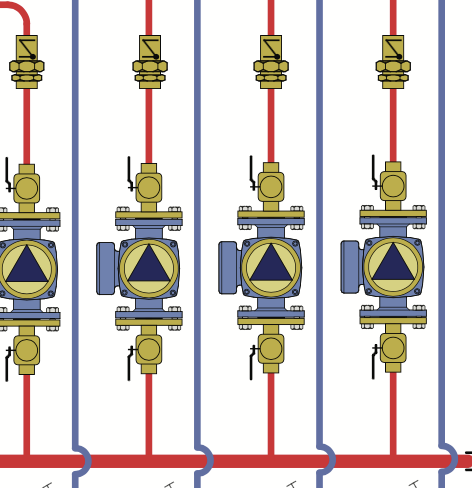
Pumps can connect off the top of a header with no issues.
Pay attention to header sizing. Add the gpm flow of the various pumps and be sure the headed can accommodate that.
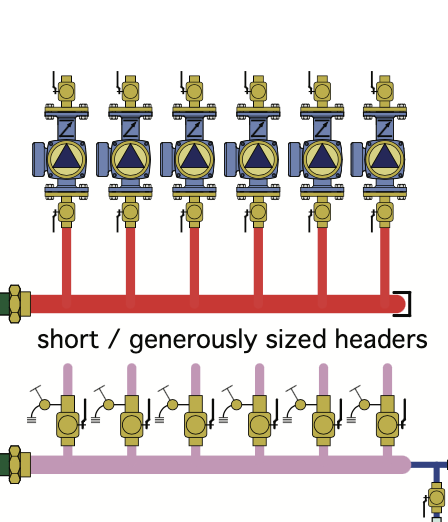
I prefer spring checks on all pumps, maybe 12" from the discharge.
 Bob "hot rod" Rohr
trainer for Caleffi NA
Living the hydronic dream0 -
- Do you have a recommended showing check part or family? My zones will be 1-1/4" and 3/4".
- The diagrams you show have isolation valves at the supply AND return headers, and also have purge valves at the return header upstream of the isolation. Do you think this is necessary, or is the "pumping away" method with isolation only at the pumps and purge only at the boiler hot output (along with an in-line shut-off) sufficient?
I'll double check my flows and see if I should up-size the supply header. I was planning on using 1-1/4 since that is what is on the boiler now, and I won't be adding any more heating area. But I will have more pumps, and if each is a little bit over sized then I might want to increase.
0 -
the valves on the return are purge valves to do zone by zone purging. You could use one 1-1/4 on the header instead of individual valves
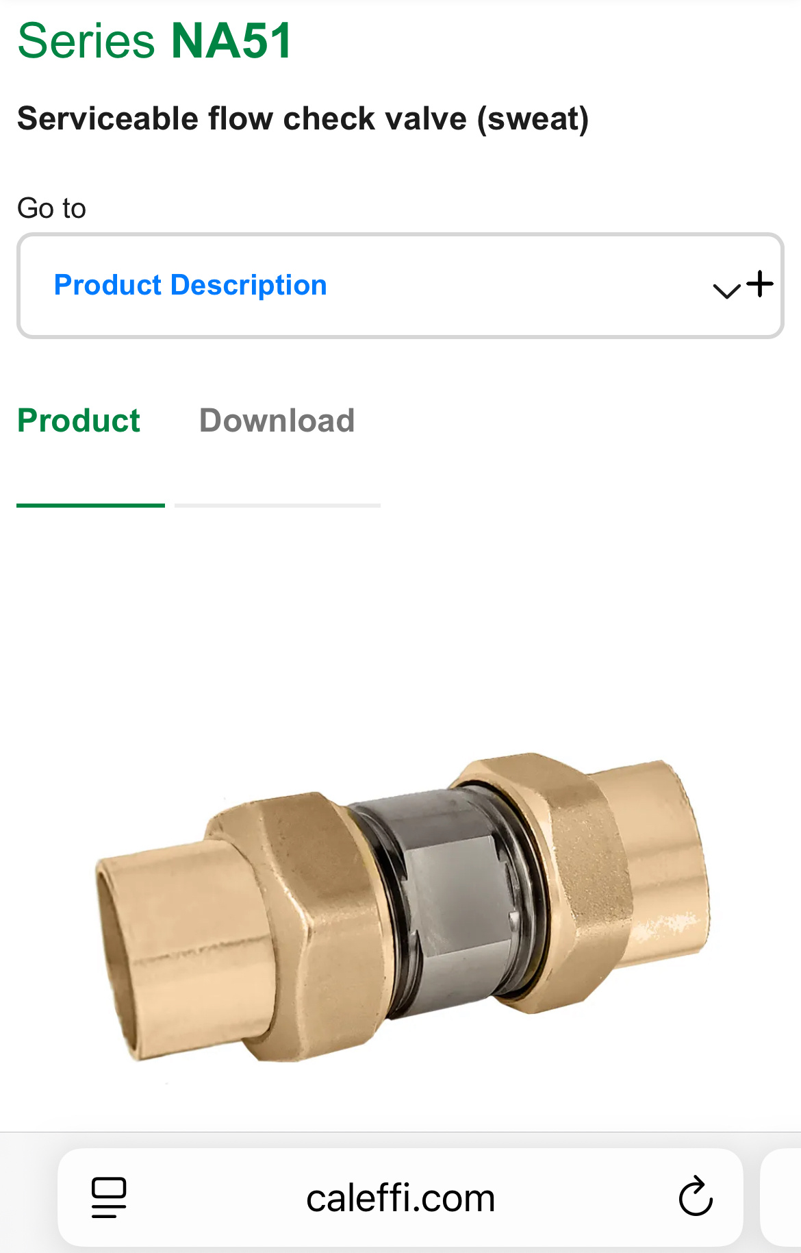
Of course I will recommend the Caleffi checks😉Unions on both ends for servicing
 Bob "hot rod" Rohr
trainer for Caleffi NA
Living the hydronic dream0

Categories
- All Categories
- 87.7K THE MAIN WALL
- 3.3K A-C, Heat Pumps & Refrigeration
- 59 Biomass
- 430 Carbon Monoxide Awareness
- 129 Chimneys & Flues
- 2.2K Domestic Hot Water
- 5.9K Gas Heating
- 122 Geothermal
- 170 Indoor-Air Quality
- 3.8K Oil Heating
- 79 Pipe Deterioration
- 1.1K Plumbing
- 6.6K Radiant Heating
- 396 Solar
- 16K Strictly Steam
- 3.5K Thermostats and Controls
- 56 Water Quality
- 51 Industry Classes
- 51 Job Opportunities
- 17 Recall Announcements